Table of Contents
Advertisement
Quick Links
Advertisement
Table of Contents

Related Manuals for Supermicro H8DGU


Summary of Contents for Supermicro H8DGU
- Page 1 ® UPER H8DGU H8DGU-F USER’S MANUAL Revision 1.0d...
- Page 2 This product, including software and documentation, is the property of Supermicro and/or its licensors, and is supplied only under a license. Any use or reproduction of this product is not allowed, except as expressly permitted by the terms of said license.
-
Page 3: About This Manual
PC users. It provides information for the installation and use of the H8DGU(-F) serverboards. The H8DGU(-F) serverboard is based on the AMD® SR5690/SP5100 chipset and supports four AMD Socket G34 type processors with up to 256 GB of DDR3- 1333/1066/800 registered ECC/Non-ECC SDRAM. - Page 4 H8DGU(-F) Serverboard User’s Manual Notes...
-
Page 5: Table Of Contents
Table of Contents Chapter 1 Introduction Overview ......................1 Checklist ......................1 Contacting Supermicro ..................2 H8DGU(-F) Quick Reference ................5 Chipset Overview ....................9 AMD SR5670/SP5100 Processor ..............9 HyperTransport Technology ................9 PC Health Monitoring ..................9 Power Confi guration Settings................10 Power Supply ....................11... - Page 6 H8DGU(-F) Serverboard User’s Manual Fan Headers ....................12 Serial Ports ....................12 T-SGPIO ...................... 13 UIO Power Connector ................. 13 LAN1/2 (Ethernet Ports) ................13 Chassis Intrusion ..................14 Overheat LED ....................14 Power LED/Speaker ..................14 ATX PS/2 Keyboard and PS/2 Mouse Ports ..........14 Unit Identifi...
- Page 7 Table of Contents Supero Doctor III ....................24 Chapter 3 Troubleshooting Troubleshooting Procedures ................1 Before Power On ....................1 No Power ......................1 No Video ......................2 Memory Errors ....................2 Losing the System’s Setup Confi guration ............2 Technical Support Procedures ................
- Page 8 H8DGU(-F) Serverboard User’s Manual Notes viii...
-
Page 9: Chapter 1 Introduction
Checklist Congratulations on purchasing your computer motherboard from an acknowledged leader in the industry. Supermicro boards are designed with the utmost attention to detail to provide you with the highest standards in quality and performance. Please check that the following items have all been included with your motherboard. -
Page 10: Contacting Supermicro
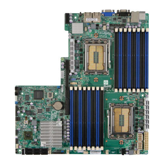
H8DGU(-F) Serverboard User’s Manual Contacting Supermicro Headquarters Address: Super Micro Computer, Inc. 980 Rock Ave. San Jose, CA 95131 U.S.A. Tel: +1 (408) 503-8000 Fax: +1 (408) 503-8008 Email: marketing@supermicro.com (General Information) support@supermicro.com (Technical Support) Web Site: www.supermicro.com Europe Address: Super Micro Computer B.V. - Page 11 Chapter 1: Introduction Figure 1-1. H8DGU-F Image...
- Page 12 H8DGU(-F) Serverboard User’s Manual Figure 1-2. H8DGU-F Motherboard Layout (not drawn to scale) COM1 JPL1 CPU2 Winbond BATTERY CPU1 JBT1 SR5670 SP5100 JWF1 SATA0 SATA2 SATA4 JOH1 FAN3 SATA1 SATA3 SATA5 Notes: Jumpers not indicated are for test purposes only.
-
Page 13: H8Dgu(-F) Quick Reference
COM1/COM2 COM1 Serial Port/Header FAN 1-8 Chassis/CPU Fan Headers IPMB System Management Bus Header for the IPMI Slot IPMI LAN Dedicated IPMI LAN Port (H8DGU-F only) Speaker Header Front Panel Connector Chassis Intrusion Header JOH1 Overheat Warning Header JPW1 20-pin Main ATX Power Connector... -
Page 14: Motherboard Features
H8DGU(-F) Serverboard User’s Manual Motherboard Features • Dual AMD Opteron 6100 series (Socket G34 type) processors Memory • Sixteen single/dual/tri/quad channel DIMM slots supporting up to 256GB of DDR3-1333/1066/800MHz registered ECC SDRAM or 64 GB of DDR3- 1333/1066/800 MHz unbuffered ECC/non-ECC SDRAM Note: Refer to Section 2-4 before installing memory and our web site for recommended DIMMs. - Page 15 • Two (2) LAN ports supported by an onboard Intel® 82576 dual port Ethernet controller for 10/100/1000Base-T • One (1) dedicated IPMI LAN port (H8DGU-F only) • ® One (1) VGA port supported by an onboard Matrox G200 graphics controller...
- Page 16 H8DGU(-F) Serverboard User’s Manual DIMM A1 HT3 Link DIMM A1 DIMM A0 8x8-3.2GT/s DIMM A0 DIMM B1 DIMM B1 DIMM B0 HT3 Link Socket G34 DIMM B0 Socket G34 DIMM C1 DIMM C1 8x8-3.2GT/s DIMM C0 CPU1 CPU2 DIMM C0...
-
Page 17: Chipset Overview
Chapter 1: Introduction Chipset Overview The H8DGU(-F) serverboard is based on the AMD SR5670/SP5100 chipset. This chipset functions as a Media and Communications Processor (MCP). Controllers for the system memory are integrated directly into AMD Opteron processors. AMD SR5670/SP5100 Processor The AMD SR5670/SP5100 are each a single-chip, high-performance HyperTrans- port peripheral controller. -
Page 18: Power Confi Guration Settings
H8DGU(-F) Serverboard User’s Manual CPU Overheat/Fan Fail LED and Control This feature is available when the user enables the CPU overheat/Fan Fail warning function in the BIOS. This allows the user to defi ne an overheat temperature. When this temperature is exceeded or when a fan failure occurs, the Overheat/Fan Fail warning LED is triggered. -
Page 19: Power Supply
It is even more important for processors that have high CPU clock rates. The H8DGU(-F) serverboard requires the use of proprietary power supplies. Please refer to the pinout information for the power connectors in Section 6 of Chapter 2 for detailed information on power requirements. - Page 20 H8DGU(-F) Serverboard User’s Manual Notes 1-12...
-
Page 21: Chapter 2 Installation
Chapter 2: Installation Chapter 2 Installation Static-Sensitive Devices Electrostatic Discharge (ESD) can damage electronic com ponents. To prevent damage to your system board, it is important to handle it very carefully. The following measures are generally suffi cient to protect your equipment from ESD. Precautions •... -
Page 22: Processor And Heatsink Installation
H8DGU-F Serverboard User's Manual Processor and Heatsink Installation Exercise extreme caution when handling and installing the processor. Always connect the power cord last and always remove it before adding, removing or changing any hardware components. Installation Procedure Follow the procedures as listed below to install the motherboard into a chassis. - Page 23 Chapter 2: Installation Use your thumb and your index fi nger to hold the CPU. Locate and align pin 1 of the CPU socket with pin 1 of the CPU. Both are marked with a triangle. Align pin 1 of the CPU with pin 1 of the socket.
-
Page 24: Mounting The Motherboard Into A Chassis
Check the Compatibility of the Motherboard Ports and the I/O Shield The H8DGU(-F) serverboard requires a chassis that can support a board of 12.1" x 13" (304 x 330 mm) in size. Make sure that the I/O ports on the motherboard align with their respective holes in the I/O shield at the rear of the chassis. - Page 25 (128-bit) memory, which is faster than non-interleaved (64-bit) memory. Maximum Memory The H8DGU(-F) serverboard supports up to 256GB of DDR3-1333/1066/800MHz registered ECC SDRAM or 64 GB of DDR3-1333/1066/800 MHz unbuffered ECC/ non-ECC SDRAM. Figure 2-1. Installing DIMM into Slot...
-
Page 26: Dimm Module Population Confi Guration
H8DGU-F Serverboard User's Manual Memory Population for Optimal Performance -For a Motherboard with One CPU (CPU1) Installed # DIMMS Channel 1 Channel 2 Channel 3 Channel 4 4 DIMMs CPU1 P1-1A P1-2A P1-3A P1-4A 8 DIMMs CPU1 P1-1A P1-1B P1-2A... - Page 27 Chapter 2: Installation Possible System Memory Allocation & Availability System Device Size Physical Memory Available (4 GB Total System Memory) Firmware Hub fl ash memory (System BIOS) 1 MB 3.99 GB Local APIC 4 KB 3.99 GB Area Reserved for the chipset 2 MB 3.99 GB I/O APIC (4 Kbytes)
-
Page 28: Pci Expansion Cards
H8DGU-F Serverboard User's Manual PCI Expansion Cards A riser card is used to support one standard size (full height full length) PCI expansion card. Installing a PCI Expansion Card Confi rm that you have the correct riser card for your chassis model and the add-on card includes a standard bracket. -
Page 29: I/O Port And Control Panel Connections
2. PS/2 Mouse 6. VGA Port 3. USB0/1 7. LAN1 4. IPMI LAN (H8DGU-F only 8. LAN2 Front Control Panel JF1 contains header pins for various front control panel connectors. See Figure 2-3 for the pin defi nitions of the various connectors. Refer to Section 2-6 for details. -
Page 30: Connector Defi Nitions
H8DGU-F Serverboard User's Manual Connector Defi nitions ATX Power 20-pin Connector Pin Defi nitions (JPW1) Pin# Defi nition Pin # Defi nition Power Connectors +3.3V +3.3V A 20-pin main power supply connector(JPW1) -12V +3.3V and two 8-pin CPU PWR connectors (JPW2/JPW3) on the motherboard. -
Page 31: Overheat/Fan Fail Led (Oh)
Chapter 2: Installation Overheat/Fan Fail LED (OH) OH/Fan Fail LED Pin Defi nitions OH/Fan Fail Connect an LED to the OH connection on (JF1) LED Status pins 7 and 8 of JF1 to provide advanced Pin# Defi nition State Indication warning of chassis overheating or fan Solid Overheat... -
Page 32: Universal Serial Bus Ports
H8DGU-F Serverboard User's Manual Universal Serial Bus Ports Universal Serial Bus Ports Pin Defi nitions (USB0/1, USB6) Two Universal Serial Bus ports (USB 2.0) are USB0 USB1 located beside the Keyboard and Mouse PS2 Pin # Defi nition Pin # Defi nition ports. -
Page 33: T-Sgpio
LAN1/2 (Ethernet Ports) Two Gigabit Ethernet ports (designated LAN1 and LAN2) are located beside the VGA port. Additionally, for the H8DGU-F serverboard, there is a dedicated LAN for IPMI on top of the two rear USB ports. These Ethernet ports accept RJ45 type cables. -
Page 34: Chassis Intrusion
H8DGU-F Serverboard User's Manual Chassis Intrusion Chassis Intrusion Pin Defi nitions A Chassis Intrusion header is located at JL1. (JL1) Attach the appropriate cable to inform you of Pin# Defi nition a chassis intrusion. Battery voltage Intrusion signal Overheat LED Overheat LED Pin Defi... -
Page 35: Unit Identifi Er Button
Chapter 2: Installation Unit Identifi er Button UID Button Pin Defi nitions In addition to the UID (Unit Identifi er) button Pin# Defi nition on the rear I/O panel, there is another UID Ground button located on the control panel. When Ground you push either UID button, both Rear Button In... -
Page 36: Jumper Settings
H8DGU-F Serverboard User's Manual Jumper Settings Connector Pins Explanation of Jumpers To modify the operation of the motherboard, Jumper jumpers can be used to choose between optional settings. Jumpers create shorts between two pins to change the function Setting of the connector. Pin 1 is identifi ed with a square solder pad on the printed circuit board. -
Page 37: I2C To Pci-Express Slot
Chapter 2: Installation I2C to PCI-Express Slot I2C to PCI-Express Slot Jumper Settings C1/JI C2 allows you to enable the I C bus (JI2C1/JI2C2) to communicate with the PCI-Express slot. Jumper Setting Defi nition For the jumpers to work properly, please set Closed Enabled both jumpers to the same setting. -
Page 38: Onboard Indicators
Dedicated IPMI LAN LEDs IPMI LAN Link LED (Left) & Activity LED (Right) A dedicated IPMI LAN is also included on Color Status Defi nition the H8DGU-F serverboard (DP5001). The Link Green: 100 Mb/s amber LED on the right indicates activity, (Left) Solid... -
Page 39: 2-10 Sata Drive Connections
Chapter 2: Installation 2-10 SATA Drive Connections SATA Ports SATA Ports Pin Defi nitions (SATA0-SATA3) There are no jumpers to confi gure the SATA Pin # Defi nition Pin # Defi nition ports, which are designated SATA0 through Ground SATA5. See the table on the right for pin defi... -
Page 40: 2-11 Enabling Sata Raid
OS installation. Building a Driver Diskette You must fi rst build a driver diskette from the Supermicro CD-ROM that was included with the system. (You will have to create this disk on a computer that is already running and with the OS installed.) -
Page 41: Enabling Sata Raid In The Bios
Chapter 2: Installation Note: You need to have an external USB fl oppy when building the driver diskette. Window's Vista, Windows 2008 or later Windows OS systems can use a USB stick instead of a fl oppy. Enabling SATA RAID in the BIOS Before installing the Windows Operating System, you must change some settings in BIOS. -
Page 42: Using The Adaptec Raid Utility
H8DGU-F Serverboard User's Manual After exiting the BIOS Setup Utility, the system will reboot. When prompted during the startup, press the <CTRL+A> key when prompted to run the Adaptec® RAID Utility program (see Figure 2-5). Figure 2-5.Adaptec RAID Utility Program Screen Using the Adaptec RAID Utility The Adaptec RAID Utility program is where you can defi... -
Page 43: 2-12 Installing Drivers
Chapter 2: Installation Highlight the fi rst "Adaptec RAID" driver shown and press the <Enter> key to install it. Press <Enter> again to continue with the Windows setup. 2-12 Installing Drivers The CD that came bundled with the system contains drivers, some of which must be installed, such as the chipset driver. -
Page 44: Supero Doctor Iii
H8DGU-F Serverboard User's Manual Supero Doctor III The Supero Doctor III program is a Web base management tool that supports remote management capability. It includes Remote and Local Management tools. The local management is called SD III Client. The Supero Doctor III program included on the CD-ROM that came with your motherboard allows you to monitor the environment and operations of your system. - Page 45 Note: Super Doctor III Software Revision 1.0 can be downloaded from our Web Site at: ftp://ftp.supermicro.com/utility/Supero_Doctor_III/. You can also download the Super Doctor III User's Guide at: <http://www.supermicro.com/ PRODUCT/Manuals/SDIII/UserGuide.pdf>. For Linux, we recommend that you use the Supero Doctor II applictation instead.
- Page 46 H8DGU-F Serverboard User's Manual Notes 2-26...
-
Page 47: Chapter 3 Troubleshooting
Chapter 3: Troubleshooting Chapter 3 Troubleshooting Troubleshooting Procedures Use the following procedures to troubleshoot your system. If you have followed all of the procedures below and still need assistance, refer to the ‘Technical Support Procedures’ and/or ‘Returning Merchandise for Service’ section(s) in this chapter. Always disconnect the AC power cord before adding, changing or installing any hardware components. -
Page 48: No Video
H8DGU-F Serverboard User's Manual Turn the power switch on and off to test the system. The battery on your motherboard may be old. Check to verify that it still supplies ~3VDC. If it does not, replace it with a new one. -
Page 49: Technical Support Procedures
Frequently Asked Questions Question: What type of memory does my motherboard support? Answer: The H8DGU(-F) serverboard supports up to 256 GB of DDR3-1333/1066 registered ECC/Non-ECC SDRAM (or 128 GB with a single CPU installed). Both single and dual channel confi guratiosn are supported. See Section 2-4 for details on installing memory. -
Page 50: Returning Merchandise For Service
H8DGU-F Serverboard User's Manual Select your motherboard model on the web page and download the corresponding BIOS fi le to your computer. Unzip the BIOS update fi le, in which you will fi nd the readme.txt (fl ash instructions), the afudos.exe (BIOS fl ash utility) and the BIOS image (xxx.rom) fi... -
Page 51: Chapter 4 Bios
Chapter 4 BIOS Introduction This chapter describes the AMIBIOS™ Setup utility for the H8DGU-F serverboard. The AMI ROM BIOS is stored in a fl ash chip and can be easily upgraded using a fl oppy disk-based program. Note: Due to periodic changes to the BIOS, some settings may have been added or deleted and might not yet be recorded in this manual. -
Page 52: Main Menu
H8DGU-F Serverboard User’s Manual Main Menu When you fi rst enter AMI BIOS Setup Utility, you will see the Main Menu screen. You can always return to the Main Menu by selecting the Main tab on the top of the screen with the arrow keys. -
Page 53: Processor And Clock Options
Chapter 4: BIOS Wait for F1 if Error This setting controls the system response when an error is detected during the boot sequence. When enabled, BIOS will stop the boot sequence when an error is detected, at which point you will need to press the F1 button to re-enter the BIOS setup menu. -
Page 54: Advanced Chipset Control
H8DGU-F Serverboard User’s Manual GART Error Reporting This option should remain disabled for normal operation. The driver developer may enable this option for testing purposes. Options are Enabled or Disabled. Microcode Update This setting Enables or Disables microcode updating. Secure Virtual Machine Mode This setting is used to Enable or Disable SVM. - Page 55 Chapter 4: BIOS Node Interleaving This option enables node memory interleaving. Options include Auto or Disabled. Channel Interleaving This option enables channel memory interleaving. Options include Auto or Disabled. CS Sparing This setting will reserve a spare memory rank in each node when enabled. Options are Enabled and Disabled.
- Page 56 H8DGU-F Serverboard User’s Manual IOMMU This setting is used to enable or disable or set the GART size in systems without AGP. Options include Enabled and Disabled. OHCI/EHCI HC Device Functions These settings allow you to either Enable or Disable functions for OHCI or EHCI bus devices.
- Page 57 Chapter 4: BIOS Primary/Secondary/Third/Fourth IDE Master/Slave LBA/Large Mode LBA (Logical Block Addressing) is a method of addressing data on a disk drive. The options are Disabled and Auto. Block (Multi-Sector Transfer) Block mode boosts IDE drive performance by increasing the amount of data transferred.
- Page 58 H8DGU-F Serverboard User’s Manual S.M.A.R.T. Self-Monitoring Analysis and Reporting Technology (SMART) can help predict impending drive failures. Select "Auto" to allow BIOS to auto detect hard disk drive support. Select "Disabled" to prevent AMI BIOS from using the S.M.A.R.T. Select "Enabled" to allow AMI BIOS to use the S.M.A.R.T. to sup- port hard drive disk.
- Page 59 Chapter 4: BIOS Load Onboard LAN 1 Option ROM This option allows you to Enable or Disable the onboard LAN 1 option ROM. Load Onboard LAN 2 Option ROM This option allows you to Enable or Disable the onboard LAN 2 option ROM. Primary Video Controller This option specifi...
- Page 60 H8DGU-F Serverboard User’s Manual Remote Access Confi guration Remote Access Use this option to Enable or Disable Remote Access in your system. If enabled, the settings below will appear. Serial Port Number Use this setting to select the serial port for console redirection. Options include COM1, COM2*.
- Page 61 Chapter 4: BIOS Hardware Health Confi guration CPU Overheat Alarm This setting allows you to specify the type of alarm for CPU overheating. Options include The Early Alarm and The Default Alarm. Fan Speed Control This feature allows the user to determine how the system will control the speed of the onboard fans.
-
Page 62: View Bmc System Event Log
H8DGU-F Serverboard User’s Manual IPMI Confi guration This menu shows static information about the IPMI fi rmware revision and status of the BMC, as well as options for IPMI confi guration. View BMC System Event Log Pressing the Enter key will open the following settings. Use the "+" and "-" keys to navigate through the system event log. - Page 63 Chapter 4: BIOS Subnet Mask In the fi eld provided here enter the Subnet address in the decimal form of xxx.xxx.xxx.xxx with xxx having a value of less than 256 and in decimal form only. The current subnet address in the BMC is shown. Gateway Address In the fi...
-
Page 64: Security Menu
H8DGU-F Serverboard User’s Manual Security Menu AMI BIOS provides a Supervisor and a User password. If you use both passwords, the Supervisor password must be set fi rst. Change Supervisor Password Select this option and press <Enter> to access the sub menu, and then type in the password. -
Page 65: Exit Menu
Chapter 4: BIOS Retry Boot Devices This option allows you to retry boot devices. Options include Enabled and Disabled. Exit Menu Select the Exit tab from AMI BIOS Setup Utility screen to enter the Exit BIOS Setup screen. Save Changes and Exit When you have completed the system confi... - Page 66 H8DGU-F Serverboard User’s Manual Notes 4-16...
-
Page 67: Appendix A Bios Error Beep Codes
Appendix A: BIOS Error Beep Codes Appendix A BIOS Error Beep Codes During the POST (Power-On Self-Test) routines, which are performed each time the system is powered on, errors may occur. Non-fatal errors are those which, in most cases, allow the system to continue the boot-up process. - Page 68 H8DGU-F Serverboard User’s Manual Notes...
-
Page 69: Appendix B Bios Post Checkpoint Codes
Appendix B: BIOS POST Checkpoint Codes Appendix B BIOS POST Checkpoint Codes When AMIBIOS performs the Power On Self Test, it writes checkpoint codes to I/O port 0080h. If the computer cannot complete the boot process, diagnostic equipment can be attached to the computer to read I/O port 0080h. B-1 Uncompressed Initialization Codes The uncompressed initialization checkpoint codes are listed in order of execution: Checkpoint... -
Page 70: B-2 Bootblock Recovery Codes
H8DGU(-F) Serverboard User’s Manual B-2 Bootblock Recovery Codes The bootblock recovery checkpoint codes are listed in order of execution: Checkpoint Code Description The onboard fl oppy controller if available is initialized. Next, beginning the base 512 KB memory test. Initializing the interrupt vector table next. -
Page 71: B-3 Uncompressed Initialization Codes
Appendix B: BIOS POST Checkpoint Codes B-3 Uncompressed Initialization Codes The following runtime checkpoint codes are listed in order of execution. These codes are uncompressed in F0000h shadow RAM. Checkpoint Code Description The NMI is disabled. Next, checking for a soft reset or a power on condition. The BIOS stack has been built. - Page 72 H8DGU(-F) Serverboard User’s Manual Checkpoint Code Description Completed post-video ROM test processing. If the EGA/VGA controller is not found, performing the display memory read/write test next. The EGA/VGA controller was not found. The display memory read/write test is about to begin.
- Page 73 Appendix B: BIOS POST Checkpoint Codes Checkpoint Code Description Shutdown was successful. The CPU is in real mode. Disabling the Gate A20 line, parity, and the NMI next. The A20 address line, parity, and the NMI are disabled. Adjusting the memory size depending on relocation and shadowing next.
- Page 74 H8DGU(-F) Serverboard User’s Manual Checkpoint Code Description Any initialization required after the option ROM test has completed. Confi guring the timer data area and printer base address next. Set the timer and printer base addresses. Setting the RS-232 base address next.
Need help?
Do you have a question about the H8DGU and is the answer not in the manual?
Questions and answers