Table of Contents
Advertisement
Advertisement
Table of Contents

Subscribe to Our Youtube Channel
Related Manuals for Supermicro H8DGU


Summary of Contents for Supermicro H8DGU
- Page 1 ® UPER H8DGU H8DGU-F USER’S MANUAL Revision 1.3...
- Page 2 Manual Revision 1.3 Release Date: March 06, 2014 Unless you request and receive written permission from Super Micro Computer, Inc., you may not copy any part of this document. Information in this document is subject to change without notice. Other products and companies referred to herein are trademarks or registered trademarks of their respective companies or mark holders.
-
Page 3: About This Manual
PC users. It provides information for the installation and use of the H8DGU(-F) serverboards. The H8DGU(-F) serverboard is based on the AMD® SR5670/SP5100 chipset and supports four AMD Socket G34 type processors with up to 128 GB of ECC/Non- ECC Unbuffered or 512 GB of ECC Registered DIMM DDR3-1600/1333/1066 Mhz SDRAM. -
Page 4: Table Of Contents
Table of Contents Chapter 1 Introduction Overview ......................1-1 Checklist ......................1-1 Contacting Supermicro ..................1-2 H8DGU(-F) Quick Reference ................1-5 Serverboard Features ..................1-6 Chipset Overview .................... 1-9 AMD SR5670/SP5100 Chipset ............... 1-9 HyperTransport Technology ................1-9 PC Health Monitoring ..................1-9 Power Confi... - Page 5 H8DGU(-F) SERVERBOARD USER'S MANUAL NMI Button ....................2-14 Universal Serial Bus Ports ............... 2-14 USB Headers ................... 2-14 Fan Headers ..................... 2-15 Serial Ports ....................2-15 IPMB ......................2-15 Unit Identifi er Button ................. 2-15 Trusted Platform Module Header ............. 2-16 T-SGPIO ....................
- Page 6 Table of Contents Using the DotHill and Adaptec RAID Utility ..........2-28 Installing the RAID Driver During OS Installation ......... 2-28 Supero Doctor III ................... 2-29 2-14 Serverboard Battery ..................2-31 Chapter 3 Troubleshooting Troubleshooting Procedures ................3-1 Before Power On .................... 3-1 No Power ......................
-
Page 7: Chapter 1 Introduction
Please check that the following items have all been included with your motherboard. If anything listed here is damaged or missing, contact your retailer. • One (1) H8DGU(-F) serverboard • Six (6) 2ft. Amphenol, SATA cable (CBL-0044L) •... -
Page 8: Contacting Supermicro
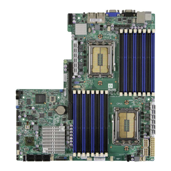
H8DGU(-F) Serverboard User’s Manual Contacting Supermicro Headquarters Address: Super Micro Computer, Inc. 980 Rock Ave. San Jose, CA 95131 U.S.A. Tel: +1 (408) 503-8000 Fax: +1 (408) 503-8008 Email: marketing@supermicro.com (General Information) support@supermicro.com (Technical Support) Web Site: www.supermicro.com Europe Address: Super Micro Computer B.V. - Page 9 Chapter 1: Introduction Figure 1-1. H8DGU-F Image...
- Page 10 H8DGU(-F) Serverboard User’s Manual Figure 1-2. H8DGU-F Serverboard Layout (not drawn to scale) COM1 JPL1 CPU2 Winbond BATTERY CPU1 JBT1 SR5670 SP5100 JWF1 SATA0 SATA2 SATA4 JOH1 FAN3 SATA1 SATA3 SATA5 Notes: Jumpers not indicated are for test purposes only.
-
Page 11: H8Dgu(-F) Quick Reference
COM1/COM2 COM1 Serial Port/Header FAN 1-8 Chassis/CPU Fan Headers IPMB System Management Bus Header for the IPMI Slot IPMI LAN Dedicated IPMI LAN Port (H8DGU-F only) Speaker Header Front Panel Connector Chassis Intrusion Header JOH1 Overheat Warning Header JPW1 20-pin Main ATX Power Connector... -
Page 12: Serverboard Features
H8DGU(-F) Serverboard User’s Manual Serverboard Features • Dual AMD Opteron 6000 series (AMD Socket G34 type) processors Memory • Sixteen (sixteen (16)) single/dual/tri/quad channel DIMM slots supporting up to 128 GB of ECC/Non-ECC Unbuffered, 512 GB of ECC Low-profi le Registered... - Page 13 • Two (2) LAN ports supported by an onboard Intel® 82576 dual port Ethernet controller for 10/100/1000Base-T • One (1) dedicated IPMI LAN port (H8DGU-F only) • ® One (1) VGA port supported by an onboard Matrox G200 graphics controller...
- Page 14 H8DGU(-F) Serverboard User’s Manual Figure 1-3. AMD SR5670/SP5100 Chipset: System Block Diagram DIMM A1 HT3 Link DIMM A1 16x16-6.4GT/s DIMM A0 DIMM A0 DIMM B1 DIMM B1 DIMM B0 HT3 Link DIMM B0 Socket G34 Socket G34 DIMM C1 DIMM C1 DIMM C0 16x16-6.4GT/s...
-
Page 15: Chipset Overview
Chapter 1: Introduction Chipset Overview The H8DGU(-F) serverboard is based on the AMD SR5670/SP5100 chipset. This chipset functions as a Media and Communications Processor (MCP). Controllers for the system memory are integrated directly into AMD Opteron processors. AMD SR5670/SP5100 Chipset The AMD SR5670/SP5100 are each a single-chip, high-performance HyperTransport peripheral controller. -
Page 16: Power Confi Guration Settings
H8DGU(-F) Serverboard User’s Manual CPU Overheat/Fan Fail LED and Control This feature is available when the user enables the CPU overheat/Fan Fail warning function in the BIOS. This allows the user to defi ne an overheat temperature. When this temperature is exceeded or when a fan failure occurs, the Overheat/Fan Fail warning LED is triggered. -
Page 17: Power Supply
It is even more important for processors that have high CPU clock rates. The H8DGU(-F) serverboard requires the use of proprietary power supplies. Please refer to the pinout information for the power connectors in Section 6 of Chapter 2 for detailed information on power requirements. -
Page 18: Uio
H8DGU(-F) Serverboard User’s Manual The H8DGU(-F) is a specially-designed serverboard that features Supermicro's UIO (Universal I/O) technology. UIO serverboards have a PCI-Express x4 and x8 signals that can support PCI-E cards or any one of several types of UIO card types to add SAS ports, additional LAN ports, Infi... -
Page 19: Chapter 2 Installation
Chapter 2: Installation Chapter 2 Installation Standardized Warning Statements About Standardized Warning Statements The following statements are industry standard warnings, provided to warn the user of situations which have the potential for bodily injury. Should you have questions or experience difficulty, contact Supermicro's Technical Support department for assistance. - Page 20 H8DGU(-F) SERVERBOARD USER'S MANUAL Warnung Bei Einsetzen einer falschen Batterie besteht Explosionsgefahr. Ersetzen Sie die Batterie nur durch den gleichen oder vom Hersteller empfohlenen Batterietyp. Entsorgen Sie die benutzten Batterien nach den Anweisungen des Herstellers. Attention Danger d'explosion si la pile n'est pas remplacée correctement. Ne la remplacer que par une pile de type semblable ou équivalent, recommandée par le fabricant.
-
Page 21: Product Disposal
Chapter 2: Installation Product Disposal Warning! Ultimate disposal of this product should be handled according to all national laws and regulations. 警告 本产品的废弃处理应根据所有国家的法律和规章进行。 警告 本產品的廢棄處理應根據所有國家的法律和規章進行。 Warnung Die Entsorgung dieses Produkts sollte gemäß allen Bestimmungen und Gesetzen des Landes erfolgen. ¡Advertencia! Al deshacerse por completo de este producto debe seguir todas las leyes y reglamentos nacionales. -
Page 22: Static-Sensitive Devices
H8DGU(-F) SERVERBOARD USER'S MANUAL Static-Sensitive Devices Electrostatic Discharge (ESD) can damage electronic com ponents. To prevent damage to your system board, it is important to handle it very carefully. The following measures are generally suffi cient to protect your equipment from ESD. -
Page 23: Processor And Heatsink Installation
Chapter 2: Installation Processor and Heatsink Installation Warning: Exercise extreme caution when handling and installing the processor. Always connect the power cord last and always remove it before adding, removing or changing any hardware components. Installation Procedure Follow the procedures as listed below to install the motherboard into a chassis. 1. - Page 24 H8DGU(-F) SERVERBOARD USER'S MANUAL 3. Use your thumb and your index fi nger to hold the CPU. Locate and align pin 1 of the CPU socket with pin 1 of the CPU. Both are marked with a triangle. 4. Align pin 1 of the CPU with pin 1 of the socket.
-
Page 25: Mounting The Serverboard Into A Chassis
Check the Compatibility of the Serverboard Ports and the I/O Shield 1. The H8DGU(-F) serverboard requires a chassis that can support a board of 12.1" x 13" (307 x 332 mm) in size. 2. Make sure that the I/O ports on the motherboard align with their respective holes in the I/O shield at the rear of the chassis. - Page 26 (128-bit) memory, which is faster than non-interleaved (64-bit) memory. Maximum Memory The H8DGU(-F) serverboard supports up to 128 GB of ECC/Non-ECC Unbuffered, 512 GB of Low-profi le ECC Registered LRDIMM, or 512 GB of ECC Registered DIMM SDRAM in sixteen (16) slots.
-
Page 27: Dimm Module Population Confi Guration
Chapter 2: Installation Memory Population for Optimal Performance -For a Serverboard with One CPU (CPU1) Installed # DIMMS Channel 1 Channel 2 Channel 3 Channel 4 4 DIMMs CPU1 P1-1A P1-2A P1-3A P1-4A 8 DIMMs CPU1 P1-1A P1-1B P1-2A P1-2B P1-3A P1-3B P1-4A... -
Page 28: Pci Expansion Cards
H8DGU(-F) SERVERBOARD USER'S MANUAL PCI Expansion Cards A riser card is used to support one standard size (full height full length) PCI expansion card. Installing a PCI Expansion Card 1. Confi rm that you have the correct riser card for your chassis model and the add-on card includes a standard bracket. -
Page 29: I/O Port And Control Panel Connections
2. PS/2 Mouse 6. VGA Port 3. USB0/1 7. LAN1 4. IPMI LAN (H8DGU-F only 8. LAN2 Front Control Panel JF1 contains header pins for various front control panel connectors. See Figure 2-3 for the pin defi nitions of the various connectors. Refer to Section 2-6 for details. -
Page 30: Connector Defi Nitions
H8DGU(-F) SERVERBOARD USER'S MANUAL Connector Defi nitions ATX Power 20-pin Connector Pin Defi nitions (JPW1) Power Connectors Pin# Defi nition Pin # Defi nition A 2 0 - p i n m a i n p o w e r s u p p l y +3.3V... -
Page 31: Reset Connector
Chapter 2: Installation Reset Connector Reset Button Pin Defi nitions The reset connector is located on pins (JF1) 3 and 4 of JF1 and attaches to the Pin# Defi nition reset switch on the computer chassis. Reset See the table on the right for pin Ground defi... -
Page 32: Hdd Led
H8DGU(-F) SERVERBOARD USER'S MANUAL HDD LED HDD LED Pin Defi nitions The HDD LED connections are located (JF1) on pins 13 and 14 of JF1. Attach a Pin# Defi nition hard-drive LED cable to display HDD or SATA activities. Refer to the table on HDD LED the right for pin defi... -
Page 33: Fan Headers
Chapter 2: Installation Fan Headers Fan Header Pin Defi nitions This motherboard has eight fan Pin# Defi nition headers (Fan1 to Fan8). These 4-pin Ground fans headers are backward compatible +12V with 3-pin fans. However, fan speed control is available for 4-pin fans only. Tachometer The fan speeds are controlled by the PWR Modulation... -
Page 34: Trusted Platform Module Header
H8DGU(-F) SERVERBOARD USER'S MANUAL Trusted Platform Module Header Trusted Platform Module Header Pin Defi nitions (JTPM1) The JTPM1 header is used to connect Pin# Defi nition Pin# Defi nition a Trusted Platform Module (TPM), LCLK available separately from a third-party vendor. -
Page 35: Power Led/Speaker
Chapter 2: Installation Power LED/Speaker PWR LED Connector Pin Defi nitions On the JD1 header, pins 1~3 are used Pin Setting Defi nition for power LED indication, and pins 4-7 Pin 1 Anode (+) are for the speaker. See the tables Pin2 Cathode (-) on the right for pin defi... -
Page 36: Lan1/2 (Ethernet Ports)
H8DGU(-F) SERVERBOARD USER'S MANUAL LAN1/2 (Ethernet Ports) LAN Ports (LAN1/2) Pin Defi nition Two Gigabit Ethernet ports (designated Pin# Defi nition Pin# Defi nition LAN1 and LAN2) are located beside P2V5SB SGND the VGA port. Additionally, there is a dedicated LAN for IPMI on top of the... -
Page 37: Uio Power Connector
Chapter 2: Installation UIO Power Connector UIO Power Connector Pin Defi nitions (UIOP) A Universal I/O (UIO) Power connector Pin# Defi nition Pin# Defi nition is located next to the UID switch. 5V_1 3V3_1 Connect this connector to the power supply to provide adequate power to 5V_2 3V3_2... -
Page 38: Jumper Settings
H8DGU(-F) SERVERBOARD USER'S MANUAL Jumper Settings Connector Pins Explanation of Jumpers To modify the operation of the Jumper motherboard, jumpers can be used to choose between optional settings. Jumpers create shorts between two Setting pins to change the function of the connector. -
Page 39: I2C To Pci-Express Slot
Chapter 2: Installation I2C to PCI-Express Slot I2C to PCI-Express Slot Jumper Settings C1/JI C2 allows you to enable the (JI2C1/JI2C2) C bus to communicate with the PCI- Jumper Setting Defi nition Express slot. For the jumpers to work Closed Enabled properly, please set both jumpers to Open... -
Page 40: 2-10 Onboard Indicators
H8DGU(-F) SERVERBOARD USER'S MANUAL 2-10 Onboard Indicators GLAN LEDs GLAN LED Activity Link Speed There are two LAN ports (LAN1/2) on the motherboard. Each Ethernet LAN port has two LEDs. The Yellow LED GLAN Activity Indicator on the right indicates connection and (Right) LED Settings activity. -
Page 41: Power Led
Chapter 2: Installation Power LED Power LED (DP2) DP2 is an Onboard Power LED. State System Status When this LED is lit, it means power Standby power present on motherboard is present on the serverboard. Be No power connected sure to turn off the system and unplug the power cord(s) before removing or installing components. -
Page 42: 2-12 Enabling Sata Raid
H8DGU(-F) SERVERBOARD USER'S MANUAL 2-12 Enabling SATA RAID Now that the hardware is set up, you must install the operating system and the SATA RAID drivers, if you wish to use RAID with your SATA drives. The installation procedure differs depending on whether you wish to have the operating system installed on a RAID array or on a separate non-RAID drive. -
Page 43: Enabling Sata Raid In The Bios
Chapter 2: Installation Enabling SATA RAID in the BIOS Before installing the Windows operating system, you must change some settings in the BIOS. Boot up the system and hit the <Delete> key to enter the BIOS Setup Utlility. After the setup utility loads, 1. - Page 44 H8DGU(-F) SERVERBOARD USER'S MANUAL Figure 2-5. DotHill RAID Utility Program Screen Figure 2-6.Adaptec RAID Utility Program Screen 2-26...
-
Page 45: 2-13 Installing Drivers
Chapter 2: Installation 2-13 Installing Drivers The Supermicro Website contains drivers and utilities for your system at ftp://ftp. supermicro.com, some of which must be installed, such as the chipset driver. After downloading and installing the drivers and utilities, the display shown in Figure 2-7 should appear. -
Page 46: Using The Dothill And Adaptec Raid Utility
H8DGU(-F) SERVERBOARD USER'S MANUAL Using the DotHill and Adaptec RAID Utility The RAID Utility program allows you to defi ne the drives you want to include in the RAID array and the mode and type of RAID. Installing the RAID Driver During OS Installation... -
Page 47: Supero Doctor Iii
Chapter 2: Installation Supero Doctor III The SuperDoctor® III program is a Web base management tool that supports remote management capability. It includes Remote and Local Management tools. The local management is called SD III Client. The SuperDoctor III program included on the CD-ROM that came with your motherboard allows you to monitor the environment and operations of your system. - Page 48 H8DGU(-F) SERVERBOARD USER'S MANUAL Figure 2-9. Supero Doctor III Interface Display Screen (Remote Control) Note: The SuperDoctor III program and User’s Manual can be downloaded from the Supermicro web site at http://www.supermicro.com/products/accessories/software/ SuperDoctorIII.cfm.For Linux, we recommend that you use the SuperoDoctor II application instead.
-
Page 49: 2-14 Serverboard Battery
Chapter 2: Installation 2-14 Serverboard Battery Caution: There is a danger of explosion if the onboard battery is installed upside down, which will reverse its polarites (see Figure 2-10). This battery must be replaced only with the same or an equivalent type recommended by the manufacturer (CR2032). - Page 50 H8DGU(-F) SERVERBOARD USER'S MANUAL Notes 2-32...
-
Page 51: Chapter 3 Troubleshooting
Chapter 3: Troubleshooting Chapter 3 Troubleshooting Troubleshooting Procedures Use the following procedures to troubleshoot your system. If you have followed all of the procedures below and still need assistance, refer to the ‘Technical Support Procedures’ and/or ‘Returning Merchandise for Service’ section(s) in this chapter. Always disconnect the AC power cord before adding, changing or installing any hardware components. -
Page 52: No Video
H8DGU(-F) SERVERBOARD USER'S MANUAL No Video 1. If the power is on but you have no video, remove all the add-on cards and cables. 2. Use the speaker to determine if any beep codes exist. Refer to Appendix A for details on beep codes. -
Page 53: Frequently Asked Questions
Frequently Asked Questions Question: What type of memory does my motherboard support? Answer: The H8DGU(-F) serverboard supports up to 128 GB of ECC/ Non-ECC Unbuffered, 512 GB of ECC Low-profile Registered LRDIMM, or 512 GB of ECC Registered DIMM DDR3-1600/1333/1066 Mhz speed, 1 GB, 2 GB, 4 GB, 8 GB, 16 GB or 32 GB size SDRAM memory (or up to 256 GB with a single CPU installed). -
Page 54: Returning Merchandise For Service
H8DGU(-F) SERVERBOARD USER'S MANUAL Question: Why can't I turn off the power using the momentary power on/off switch? Answer: The instant power off function is controlled in BIOS by the Power Button Mode setting. When the On/Off feature is enabled, the motherboard will have instant off capabilities as long as the BIOS has control of the system. -
Page 55: Chapter 4 Bios
Chapter 4 BIOS Introduction This chapter describes the AMIBIOS™ Setup utility for the H8DGU(-F) serverboard. The 16 Mb AMI BIOS® is stored in a fl ash chip and can be easily upgraded using a fl oppy disk-based program. Note: Due to periodic changes to the BIOS, some settings may have been added or deleted and might not yet be recorded in this manual. -
Page 56: Main Menu
H8DGU(-F) Serverboard User’s Manual Main Menu When you fi rst enter AMI BIOS Setup Utility, you will see the Main Menu screen. You can always return to the Main Menu by selecting the Main tab on the top of the screen with the arrow keys. - Page 57 Chapter 4: BIOS Wait for F1 if Error This setting controls the system response when an error is detected during the boot sequence. When enabled, BIOS will stop the boot sequence when an error is detected, at which point you will need to press the F1 button to re-enter the BIOS setup menu.
-
Page 58: Processor And Clock Options
H8DGU(-F) Serverboard User’s Manual Processor and Clock Options CPU Confi guration This displays static information on the Module Version, Physical Count and Logical Count for the system's processor(s) and clock. CPU Information The information for the installed processor includes Revision, Cache L1/L2/L3, Speed, NB CLK, Able to Change Frequency and uCode Patch Level. -
Page 59: Advanced Chipset Control
Chapter 4: BIOS CPU Down Core Mode This option sets down core support for the CPU. Options include Disabled, 1 Core through n Cores in odd numbered increments. The value n is depend on the core per CPU node. C1E Support This option enables C1E support. - Page 60 H8DGU(-F) Serverboard User’s Manual Bank Swizzle Mode This setting Enables or Disables the bank swizzle mode. ECC Confi guration ECC Mode This submenu affects the DRAM scrub rate based on its setting. Options include Disabled, Basic, Good, Super, Max and User. Selecting User activates the other options for user setting.
- Page 61 Chapter 4: BIOS SouthBridge Chipset Confi guration OHCI/EHCI HC Device Functions These settings allow you to either Enable or Disable functions for OHCI or EHCI bus devices. USB 2.0 Controller Mode Use this setting to confi gure the USB 2.0 Controller in either Hi-Speed (480 Mps) or Full Speed (12 Mps) mode.
- Page 62 H8DGU(-F) Serverboard User’s Manual Primary/Secondary/Third/Fourth IDE Master/Slave LBA/Large Mode LBA (Logical Block Addressing) is a method of addressing data on a disk drive. The options are Disabled and Auto. Block (Multi-Sector Transfer) Block mode boosts IDE drive performance by increasing the amount of data transferred.
- Page 63 Chapter 4: BIOS S.M.A.R.T. Self-Monitoring Analysis and Reporting Technology (SMART) can help predict impending drive failures. Select "Auto" to allow BIOS to auto detect hard disk drive support. Select "Disabled" to prevent AMI BIOS from using the S.M.A.R.T. Select "Enabled" to allow AMI BIOS to use the S.M.A.R.T. to support hard drive disk.
- Page 64 H8DGU(-F) Serverboard User’s Manual PCIe Slot from SXB1 This setting Enables or Disables the slot OPROM for the SXB1 slot. PCIe Slot rom SXB2 This setting Enables or Disables the slot OPROM for the SXB2 slot. Onboard LAN Option ROM Select This setting allows you to select the onboard LAN option ROM for iSCSI or PXE.
- Page 65 Chapter 4: BIOS Remote Access Confi guration Remote Access Use this option to Enable or Disable Remote Access in your system. If enabled, the settings below will appear. Serial Port Number Use this setting to select the serial port for console redirection. Options include COM1, COM2*.
- Page 66 H8DGU(-F) Serverboard User’s Manual Hardware Health Confi guration CPU Overheat Alarm This setting allows you to specify the type of alarm for CPU overheating. Options include The Early Alarm and The Default Alarm. Fan Speed Control This feature allows the user to determine how the system will control the speed of the onboard fans.
- Page 67 Chapter 4: BIOS Default Alarm (default setting) is enabled when the Tctl value = 70, and is disabled when the Tctl value drops from 70 to 67. When COA (either Early or Default Alarm) is enabled, the following actions are required to be executed: •...
-
Page 68: View Bmc System Event Log
H8DGU(-F) Serverboard User’s Manual ACPI Confi guration PS2 KB/MS Wakeup This setting allows you to Enable or Disable PS2 keyboard and mouse wakeup. ACPI Aware O/S This setting Enables or Disables ACPI support for the system's operating system. Options include Yes (enabled) or No (disabled). - Page 69 Chapter 4: BIOS Set LAN Confi guration Use the "+" and "-" keys to choose the desired channel number. This displays Channel Number and Channel Number Status information. This menu contains options for inputing settings for the SET LAN Confi guration Command.
-
Page 70: Security Menu
H8DGU(-F) Serverboard User’s Manual Event Log Confi guration View Event Log Pressing the Enter key will open the event log. Use the "" and "" keys to navigate through the system event log. Mark All Events as Read Selecting this and pressing the Enter key marks all events as read in the event log. -
Page 71: Boot Menu
Chapter 4: BIOS Boot Menu Boot Device Priority This feature allows you to prioritize the boot sequence from the list of available devices. A device that is in parenthesis has been disabled in the corresponding type menu. Removable Drives This feature allows you to specify the boot sequence from the list of available removable drives. -
Page 72: Exit Menu
H8DGU(-F) Serverboard User’s Manual Retry Boot Devices This option allows you to retry boot devices. Options include Enabled and Disabled. Exit Menu Select the Exit tab from AMI BIOS Setup Utility screen to enter the Exit BIOS Setup screen. Save Changes and Exit When you have completed the system confi... -
Page 73: Appendix A Bios Error Beep Codes
Appendix A: BIOS Error Beep Codes Appendix A BIOS Error Beep Codes During the POST (Power-On Self-Test) routines, which are performed each time the system is powered on, errors may occur. Non-fatal errors are those which, in most cases, allow the system to continue the boot-up process. - Page 74 H8DGU(-F) Serverboard User’s Manual Notes...
-
Page 75: Appendix B Bios Post Checkpoint Codes
Appendix B: BIOS POST Checkpoint Codes Appendix B BIOS POST Checkpoint Codes When AMIBIOS performs the Power On Self Test, it writes checkpoint codes to I/O port 0080h. If the computer cannot complete the boot process, diagnostic equipment can be attached to the computer to read I/O port 0080h. B-1 Uncompressed Initialization Codes The uncompressed initialization checkpoint codes are listed in order of execution: Checkpoint... -
Page 76: B-2 Bootblock Recovery Codes
H8DGU(-F) SERVERBOARD USER'S MANUAL B-2 Bootblock Recovery Codes The bootblock recovery checkpoint codes are listed in order of execution: Checkpoint Code Description The onboard fl oppy controller if available is initialized. Next, beginning the base 512 KB memory test. Initializing the interrupt vector table next. -
Page 77: B-3 Uncompressed Initialization Codes
Appendix B: BIOS POST Checkpoint Codes B-3 Uncompressed Initialization Codes The following runtime checkpoint codes are listed in order of execution. These codes are uncompressed in F0000h shadow RAM. Checkpoint Code Description The NMI is disabled. Next, checking for a soft reset or a power on condition. The BIOS stack has been built. - Page 78 H8DGU(-F) SERVERBOARD USER'S MANUAL Checkpoint Code Description Bus initialization system, static, output devices will be done next, if present. See the last page for additional information. Completed post-video ROM test processing. If the EGA/VGA controller is not found, performing the display memory read/write test next.
- Page 79 Appendix B: BIOS POST Checkpoint Codes Checkpoint Code Description The memory above 1 MB has been tested and initialized. Saving the memory size information next. The memory size information and the CPU registers are saved. Entering real mode next. Shutdown was successful. The CPU is in real mode. Disabling the Gate A20 line, parity, and the NMI next.
- Page 80 H8DGU(-F) SERVERBOARD USER'S MANUAL Checkpoint Code Description Initialization before the C800 adaptor ROM gains control has completed. The adaptor ROM check is next. The adaptor ROM had control and has now returned control to BIOS POST. Performing any required processing after the option ROM returned control.
Need help?
Do you have a question about the H8DGU and is the answer not in the manual?
Questions and answers