
Related Manuals for Owon MSO7102TD


Summary of Contents for Owon MSO7102TD
- Page 1 MSO Series Portable Mixed Signal Digital Storage Oscilloscope User Manual ■MSO7102TD ■MSO8102T ■MSO8202T WWW.OWON.COM.CN...
- Page 2 OWON is the registered trademark of the Lilliput Company. Xiamen Lilliput Technology Co.,Ltd.: the 5th floor, B Area, Chuangxin Mansion, Software Park,ZhenZhuWan, Huandao RD, Xiamen,Fujian,China Fujian Lilliput Optoelectronics Technology Co.,Ltd.:The mansion of optoelectronics hengsan road,...
- Page 3 User Manual of OWON Color Mixed Signal Digital Storage Oscilloscope General Warranty The Lilliput warrants that the product will be free from defects in materials and workmanship for a period of three years from the date of purchase of the product by the original purchaser from the Lilliput company.
-
Page 4: Table Of Contents
User Manual of OWON Color Mixed Signal Digital Storage Oscilloscope Table of Contents 1.General Safety Requirements................... 3 2.Safety Terms and Symbols....................4 3.General Characteristics of the MSO Series Oscilloscope ..........6 4.Junior User Guidebook ....................7 4.1 Introduction to the Front Panel and the User's Interface of the MSO series Oscilloscope .......................... - Page 5 User Manual of OWON Color Mixed Signal Digital Storage Oscilloscope How to Implement the Auxiliary System Function Setting..............63 How to Implement the Automatic Measurement..................65 How to Implement the Cursor Measurement ..................67 How to use Autoscale..........................73 How to Use Executive Buttons....................... 75 5.2Logic analyzer........................
-
Page 6: General Safety Requirements
User Manual of OWON Color Mixed Signal Digital Storage Oscilloscope 1.General Safety Requirements Before any operations, please read the following safety precautions to avoid any possible bodily injury and prevent this product or any other products connected from damage. In order to avoid any contingent danger, this product is only used within the range specified. -
Page 7: Safety Terms And Symbols
User Manual of OWON Color Mixed Signal Digital Storage Oscilloscope 2.Safety Terms and Symbols Terms in this manual. The following terms may appear in this manual: Warning. A warning statement indicates the conditions and actions which may endanger the life safety. - Page 8 User Manual of OWON Color Mixed Signal Digital Storage Oscilloscope To avoid body damage and prevent product and connected equipment dam. This product can only be used in the specified applications. Carefully read the following safety information before using the test tool.
-
Page 9: General Characteristics Of The Mso Series Oscilloscope
User Manual of OWON Color Mixed Signal Digital Storage Oscilloscope 3.General Characteristics of the MSO Series Oscilloscope Digital Storage Oscilloscope Model Bandwidth Sample Rate MSO7102TD 100MHz 1GS/s half channel*, 500MS/s each channel MSO8102T 100MHz 2GS/s half channel*, 1G S/s each channel... -
Page 10: Junior User Guidebook
User Manual of OWON Color Mixed Signal Digital Storage Oscilloscope 4.Junior User Guidebook This chapter deals with the following topics mainly: Digital Storage Oscilloscope Introduction to the front panel and the user’s interface of the MSO series oscilloscope How to implement the general inspection... -
Page 11: Introduction To The Front Panel And The User's Interface Of The Mso Series Oscilloscope
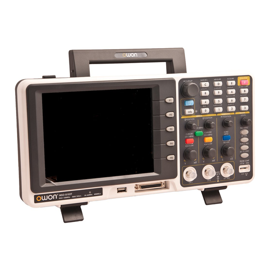
User Manual of OWON Color Mixed Signal Digital Storage Oscilloscope 4.1 Introduction to the Front Panel and the User's Interface of the MSO series Oscilloscope When you get a new-type oscilloscope, you should get acquainted with its front panel at first and the MSO series mixed digital storage oscilloscope is no exception. -
Page 12: Contrlo(Key And Knob) Area
User Manual of OWON Color Mixed Signal Digital Storage Oscilloscope 8、 Power and charging indication: Green light indicate AC supply and battery full charged; yellow light indicate under charging. Contrlo(key and knob) area Fig. 4-2 Keys Overview 1、Menu option setting: F1~F5 2、Switch... - Page 13 User Manual of OWON Color Mixed Signal Digital Storage Oscilloscope “Volts/Div” knob control voltage scale of CH1, CH2. For LA, “CH1 menu”, “CH2 menu”, “Wave math” keys and “CH2 Volts/Div” knob are idle. “CH1 Vertical”, “CH2 Vertical” to adjust the M1, M2 position in Cursor menu when cursor display is on “CH1 Volts/Div”.
-
Page 14: Digital Storage Oscilloscope
User Manual of OWON Color Mixed Signal Digital Storage Oscilloscope 4.2Digital Storage Oscilloscope User interface introduction Fig. 4-3 Illustrative Drawing of Display Interfaces 1. The Trigger State indicates the following information: Auto: The oscilloscope is under the Automatic mode and is collecting the waveform under the non-trigger state. - Page 15 User Manual of OWON Color Mixed Signal Digital Storage Oscilloscope 5. This reading shows the time deviation between the horizontal trigger position and the window centre line, which is regarded as 0 in the window center. 6. It indicates the current function menu.
-
Page 16: How To Implement The General Inspection
User Manual of OWON Color Mixed Signal Digital Storage Oscilloscope waveform of the CH1 channel. If the pointer is not displayed, it shows that the channel is not opened. 22. The positions of two purple dotted line cursors measurements. 23. The reading shows the frequence of the two channels. It is a 6 digits cymometer.Its measurement range of frequency is 2Hz to full bandwidth. -
Page 17: How To Implement The Probe Compensation
User Manual of OWON Color Mixed Signal Digital Storage Oscilloscope 10X, Set the Switch in the Oscilloscope Probe as 10X and Connect the Oscilloscope with CH1 Channel. Align the slot in the probe with the plug in the CH1 connector BNC, and then tighten the probe with rotating it to the right side. -
Page 18: How To Set The Probe Attenuation Coefficient
User Manual of OWON Color Mixed Signal Digital Storage Oscilloscope probe connector, and then press the button “7(AUTOSET)”. 2. Check the displayed wave forms and regulate the probe till a correct compensation is achieved (see Fig.4-5 and Fig.4-6). Fig. 4-5 Displayed Wave Forms of the Probe Compensation 3. -
Page 19: How To Use The Probe Safely
User Manual of OWON Color Mixed Signal Digital Storage Oscilloscope Fig.4-7 Attenuation Switch Note: When the attenuation switch is set to 1X, the probe will limit the bandwidth of the oscilloscope in 5MHz. If it is needed to use the whole bandwidth of the oscilloscope, the switch must be set to 10X. - Page 20 User Manual of OWON Color Mixed Signal Digital Storage Oscilloscope the using of the vertical setting. Fig. 4-9 Vertical Control Zone 1. Use the button “VERTICAL POSITION” knob to show the signal in the center of the waveform window. The “VERTICAL POSITION” knob functions the regulating of the vertical display position of the signal.
-
Page 21: Introduction To The Horizontal System
“Horizontal Time Base” display in the status bar changes accordingly. The horizontal scanning speed steps from 2 ns up to 100s in the sequence of 1-2-5 -----MSO7102TD,MSO8102T; 1 ns up to 100s in the sequence of 1-2-5 -----MSO8202T. 2. Use the “HORIZONTAL POSITION” knob to adjust the horizontal position of the signal in the waveform window. -
Page 22: Introduction To The Trigger System
User Manual of OWON Color Mixed Signal Digital Storage Oscilloscope Introduction to the Trigger System Shown as Fig.4-11, there are a knob and four buttons in the “TRIGGER CONTROLS”. The following practices will direct you to be familiar with the setting of the trigger system gradually. -
Page 23: Logic Analyzer
User Manual of OWON Color Mixed Signal Digital Storage Oscilloscope 4.3Logic Analyzer LA input connection Insert the plug of OL-16 LA module 50P into the LA signal input on front panel and fix two screw. Then 16 channel clamp of OL-16 LA connect to target singal and ready for... -
Page 24: How To Acquire Data
User Manual of OWON Color Mixed Signal Digital Storage Oscilloscope detected and wait for sample finished. “STOP” for sampling finished。 12、Value indicate current time base。 13、Info windows: different operation display different info。 14、Value display current filter modulus setting。 15、Value display current sample rate setting。... -
Page 25: Display Systems
User Manual of OWON Color Mixed Signal Digital Storage Oscilloscope Clock is in effect when enable is low clock data, and clock frequency is 1M, data width is 32 digits, every clock corresponds to one data. Signal voltage is 3.3V. -
Page 26: Trigger System
User Manual of OWON Color Mixed Signal Digital Storage Oscilloscope Fig.4-14 Fig. 4-15 Trigger system LA is same as DSO and need to make trigger to synchronize data. The trigger system mainly to set trigger sources, trigger mode and trigger position. -
Page 27: Threshold Voltage System
User Manual of OWON Color Mixed Signal Digital Storage Oscilloscope Fig. 4-16 Threshold voltage system Threshold voltage system is to set high/low of the trigger voltage. The system already fixed the setting for normal logic voltage as CMOS, LVMOS etc. And you can set any trigger voltage using custom setting. -
Page 28: Sampling System
User Manual of OWON Color Mixed Signal Digital Storage Oscilloscope Sampling system The waveform accuracy reverts from sample data depend on sample rate for measured signals. The waveform reverted in LA is referring to the sample signals storage in the memory. The recorded data will display in error if the sample rate is too lower. - Page 29 User Manual of OWON Color Mixed Signal Digital Storage Oscilloscope Fig. 4-19...
-
Page 30: Advanced User Guidebook
User Manual of OWON Color Mixed Signal Digital Storage Oscilloscope 5.Advanced User Guidebook Up till now, you have already been familiar with the initial operations of the functions of the function areas, buttons and knobs in the front panel of the MSO series oscilloscope. -
Page 31: Digital Storage Oscilloscope
User Manual of OWON Color Mixed Signal Digital Storage Oscilloscope How to set Utility It is recommended that you read this chapter carefully to get acquainted the various measurement functions and other operation methods of the MSO series oscilloscope. 5.1Digital Storage Oscilloscope... - Page 32 User Manual of OWON Color Mixed Signal Digital Storage Oscilloscope The description of the Channel Menu is shown as the following list: Function Menu Setting Description Block the DC component in the input signal. Unblock the AC and DC components in the input Coupling signal.
- Page 33 User Manual of OWON Color Mixed Signal Digital Storage Oscilloscope Fig. 5-2 AC Coupling Oscillogram Fig. 5-3 DC Coupling Oscillogram Setting the“Band Limit” Taking the Channel 1 for example, the operation steps are shown as below: (1). Press the CH1 MENU button and call out the CH1 SETUP menu.
- Page 34 User Manual of OWON Color Mixed Signal Digital Storage Oscilloscope Setting the Channel “ON/OFF” Taking the Channel 1 for example, the operation steps are shown as below: (1). Press the CH1 MENU button and call out the CH1 SETUP menu.
- Page 35 User Manual of OWON Color Mixed Signal Digital Storage Oscilloscope Fig. 5-5 Regulation of the Attenuation Ratio of the Probe A List of the Attenuation Coefficient of Probes and the Corresponding Menu Settings. Attenuation Coefficient of the Probe Corresponding Menu Setting...
-
Page 36: Implementation Of Mathematical Manipulation Function
User Manual of OWON Color Mixed Signal Digital Storage Oscilloscope Fig. 5-6 Wave Form not inverted Fig. 5-7 Wave Form Inverted Implementation of Mathematical Manipulation Function The Mathematical Manipulation function is used to show the results of the additive,multiplication,division and subtraction operations between Channel 1 and Channel 2, and the FFT operation of CH1 or CH2 . -
Page 37: Using Fft Function
User Manual of OWON Color Mixed Signal Digital Storage Oscilloscope Setting Description CH1-CH2 Subtract the Channel 2 wave form from the Channel 1 wave form. CH2-CH1 Subtract the Channel 1 wave form from the Channel 2 wave form. CH1+CH2 Add the Channel 1 wave form to the Channel 2. - Page 38 User Manual of OWON Color Mixed Signal Digital Storage Oscilloscope Function Menu Setting Instruction Turn on FFT function. Turn off FFT function. Select CH1 as FFT source. Source Select CH2 as FFT source. Rectangle Blackman Window Select window for FFT.
- Page 39 User Manual of OWON Color Mixed Signal Digital Storage Oscilloscope characteristics help you to determine which window to use. Use the following guidelines to select the best window. Type Description Window This is the best type of window for resolving...
- Page 40 User Manual of OWON Color Mixed Signal Digital Storage Oscilloscope Fig.5-9. Blackman window Fig.5-10 . Hamming window...
- Page 41 User Manual of OWON Color Mixed Signal Digital Storage Oscilloscope Fig.5-11. Rectangle window Fig..5-12 . Hanning window Quick Tips If desired, use the zoom feature to magnify the FFT waveform. Use the default dBV RMS scale to see a detailed view of multiple frequencies, even if they have very different amplitudes.
-
Page 42: Application Of Vertical Position And Volts/Div Knobs
User Manual of OWON Color Mixed Signal Digital Storage Oscilloscope on the source signal. To reduce random noise and aliased components in repetitive or single-shot events, set the oscilloscope acquisition mode to average. Term interpretation Nyquist frequency: The highest frequency that any Real Time Digital Oscilloscope can measure is exactly half of the sampling rate under the condition of no mistakes,which is called Nyquist frequency. -
Page 43: How To Set The Horizontal System
User Manual of OWON Color Mixed Signal Digital Storage Oscilloscope Fig. 5-13 Information about Vertical Position How to Set the Horizontal system The HORIZONTAL CONTROLS includes the HORIZONTAL NENU button and such knobs as HORIZONTAL POSITION and SEC/DIV. 1. HORIZONTAL POSITION knob: this knob is used to adjust the horizontal positions of all channels (include those obtained from the mathematical manipulation), the analytic resolution of which changes with the time base. - Page 44 User Manual of OWON Color Mixed Signal Digital Storage Oscilloscope Fig. 5-14 Time Base Mode Menu The description of the Horizontal Menu is as follows: Function Menu Setting Description The setting of the horizontal main time base is Main Time Base used to display the wave form.
- Page 45 User Manual of OWON Color Mixed Signal Digital Storage Oscilloscope Fig. 5-15 Main Time Base Set Window Press the F2 menu selection button and choose Set Window. The screen will show a window area defined by two cursors. In this case, the HORIZONTAL POSITION and SEC/DIV knobs can be used to adjust the horizontal position and size of this window area.
-
Page 46: How To Set Trigger System
User Manual of OWON Color Mixed Signal Digital Storage Oscilloscope Fig..5-17 Set Window isable under FFT mode Window Expansion Press the F3 menu selection button and choose Zone Window. As a result, the window area defined by two cursors will be expanded to the full screen size (see Fig. - Page 47 User Manual of OWON Color Mixed Signal Digital Storage Oscilloscope waveform. When DSO start to acquire data it will acquire enough data to form waveform on left of trigger point. DSO continues to acquire data when it waits for trigger condition happen.
- Page 48 User Manual of OWON Color Mixed Signal Digital Storage Oscilloscope Fig. 5-19 Edge trigger menu Edge menu list: MENU SETTING INSTRUCTION Select CH1 as the trigger source. Select CH2 as the trigger source. Source Ext-trigger EXT/5 Ext-trigger divide to 5 and extend trigger level range.
- Page 49 User Manual of OWON Color Mixed Signal Digital Storage Oscilloscope Fig. 5-20 Video trigger menu Video menu list MENU SETTING INSTRUCTION elect CH1 as the trigger source. Select CH2 as the trigger source. Source Ext-trigger EXT/5 Ext-trigger divide to 5 to extend trigger level range...
- Page 50 User Manual of OWON Color Mixed Signal Digital Storage Oscilloscope Fig. 5-21 Pulse Width Trigger menu Pulse Width Trigger menu list MENU SETTING INSTRUCTION Select CH1 as the trigger source. Source Select CH2 as the trigger source. Mode Pulse (+pulse width less than )
- Page 51 User Manual of OWON Color Mixed Signal Digital Storage Oscilloscope Slope Trigger Slope trigger sets the oscilloscope as the positive/negative slope trigger within the specified time. The Slope Trigger Menu is shown as Fig. 5-22 Fig. 5-22 Slope Trigge menu...
- Page 52 User Manual of OWON Color Mixed Signal Digital Storage Oscilloscope Alternate trigger Trigger signal comes from two vertical channels when alternate trigger is on. This mode is used to observe two unrelated signals. You can choose different trigger modes for different channels.The options are as follows: edge, video, pulse or slope.
- Page 53 User Manual of OWON Color Mixed Signal Digital Storage Oscilloscope Alternate trigger(Trigger Mode:video) Alternate trigger(Trigger Type:video) Me Fig.5-24 nu is shown as Fig.5-24 Alternate trigger(Trigger Type:video) Menu Alternate trigger(Trigger Type: video) list: Menu MENU SETTING INSTRUCTION elect CH1 as the trigger source.
- Page 54 User Manual of OWON Color Mixed Signal Digital Storage Oscilloscope Alternate trigger(Trigger Mode: Pulse) Alternate trigger(Trigger Type: Pulse) Fig.5-25 Menu is shown as Fig.5-25 Alternate trigger(Trigger Type: Pulse) Menu Alternate trigger(Trigger Type: Pulse) menu list MENU SETTING INSTRUCTION Select CH1 as the trigger source.
- Page 55 User Manual of OWON Color Mixed Signal Digital Storage Oscilloscope Alternate trigger(Trigger Mode: Slope ) Alternate trigger(Trigger Type: Slope )Menu is shown as Fig.5-26. Alternate trigger(Trigger Type: Slope )Menu Fig.5-26 Alternate trigger(Trigger Type: ) menu list: Slope MENU SETTING INSTRUCTION elect CH1 as the trigger source.
- Page 56 User Manual of OWON Color Mixed Signal Digital Storage Oscilloscope Term interpretation 1. Source: Trigger can occur from several sources: Input channels (CH1, CH2), AC Line, Ext, Ext/5. Input :It is the most commonly used trigger source. The channel will work when selected as a trigger source whatever displayed or not.
-
Page 57: How To Operate The Function Menu
User Manual of OWON Color Mixed Signal Digital Storage Oscilloscope How to Operate the Function Menu The function menu control zone includes 7 function menu buttons and 3 immediate-execution buttons: SAVE/RCL, MEASURE, ACQUIRE, UTILITY, CURSOR, DISPLAY, AUTOSCALE,AUTOSET, RUN/STOP and U-DISK COPY. - Page 58 User Manual of OWON Color Mixed Signal Digital Storage Oscilloscope Fig.5-28 Peak Detect mode, under which the burrs on the falling edge of the square wave, can be detected and the noise is heavy. Fig.5-29 Common ACQU Mode display, in which no burr can be detected.
-
Page 59: How To Set The Display System
User Manual of OWON Color Mixed Signal Digital Storage Oscilloscope Fig.5-30 The displayed wave form after the noise is removed under the Average Mode, in which the average number of 16 is set. How to Set the Display System Push down the DISPLAY button and the menu displayed in the screen is shown as Fig.5-31. - Page 60 User Manual of OWON Color Mixed Signal Digital Storage Oscilloscope Function Menu Setting Description Vectors The space between the adjacent sampling points in the display is filled with the vector form. Type Dots Only the sampling points are displayed. 1sec...
- Page 61 User Manual of OWON Color Mixed Signal Digital Storage Oscilloscope Fig.5-33 Display in Dots form Persist When the Persist function is used, the persistence display effect of the picture tube oscilloscope can be simulated: the reserved original data is displayed in fade color and the new data is in bright color.
- Page 62 User Manual of OWON Color Mixed Signal Digital Storage Oscilloscope XY Format This format is only applicable to Channel 1 and Channel 2. After the XY display format is selected, Channel 1 is displayed in the horizontal axis and Channel 2 in the vertical axis;...
- Page 63 User Manual of OWON Color Mixed Signal Digital Storage Oscilloscope Fig.5-36 Fig.5-36 FFT mode XY Format Disable...
-
Page 64: How To Save And Recall A Wave Form
User Manual of OWON Color Mixed Signal Digital Storage Oscilloscope How to Save and Recall a Wave Form Press the SAVE/RCL button, you can save and call out the waveforms in the instrument. The menu displayed in the screen is shown as Fig.5-37. - Page 65 User Manual of OWON Color Mixed Signal Digital Storage Oscilloscope 4. Press the F4 menu selection button and choose ON for CH A. The stored wave form A will be displayed in the screen. The voltage level and time base level will also be shown at the upper left corner of the display area at the same time (see Fig.5-38).
-
Page 66: How To Implement The Auxiliary System Function Setting
User Manual of OWON Color Mixed Signal Digital Storage Oscilloscope How to Implement the Auxiliary System Function Setting Press the UNTILITY button and the menu is displayed in the screen as Fig.5-40. Fig.5-40 Function Menu The description of the Auxiliary Function Menu is shown as the following table. - Page 67 User Manual of OWON Color Mixed Signal Digital Storage Oscilloscope Fig.5-41 SYS STAT Menu The “SYS STAT” menu is described as the following table: Function Menu Setting Description Horizontal Show the horizontal parameter of the channel. Vertical Show the vertical parameter of the channel.
-
Page 68: How To Implement The Automatic Measurement
User Manual of OWON Color Mixed Signal Digital Storage Oscilloscope Horizontal System State Fig.5-42 How to Implement the Automatic Measurement With the Measure button pressed down, an automatic measurement can be implemented. There are 20 types of measurements and 4 measurement results can be displayed simultaneously. - Page 69 User Manual of OWON Color Mixed Signal Digital Storage Oscilloscope +Duty: +Duty Cycle, defined as +Width/Period. -Duty: -Duty Cycle, defined as -Width/Period. Press the F1 menu selection button to choose Source or Type menu. You can choose the channel to be measured from the Source menu and choose the measurement Type (Freq, Period, Mean, PK–PK, and Cyc RMS).
-
Page 70: How To Implement The Cursor Measurement
User Manual of OWON Color Mixed Signal Digital Storage Oscilloscope 9. Press the F4 menu selection button and choose Mean. 10. Press the F5 menu selection button and choose Cyc RMS. The measured value will be displayed in the reading window automatically (see Fig.5-44). - Page 71 User Manual of OWON Color Mixed Signal Digital Storage Oscilloscope Fig.5-45 CURS MEAS Menu The description of the cursor measurement menu is shown as the following table: Function Menu Setting Description Switch off the cursor measurement. Voltage Display the voltage measurement cursor and Type menu.
- Page 72 User Manual of OWON Color Mixed Signal Digital Storage Oscilloscope indicating CURSOR1 and CURSOR2. 3. Press the F2 menu selection button and choose CH1 for Source. 4. Adjust the positions of CURSOR1 and CURSOR2 according to the measured waveform, with the absolute value of the voltage amplitude difference between Cursor 1 and Cursor 2 displayed in the increment window.
- Page 73 User Manual of OWON Color Mixed Signal Digital Storage Oscilloscope Fig.5-47 Wave Form of Cursor Measurement the Cursor Measurement for FFT model: Press the CURSOR button to display the cursor measurement function menu (CURS MEAS) in the screen, which includes Vamp Measurement and Freq Measurement at the mode of FFT, shown as Fig.5-48.
- Page 74 User Manual of OWON Color Mixed Signal Digital Storage Oscilloscope Function Menu Setting Description Switch off the cursor measurement. Vamp Display the Vamp measurement cursor and Type menu. Freq Display the Freq measurement cursor and menu. Source MATH FFT Display the channel for the cursor measure.
- Page 75 User Manual of OWON Color Mixed Signal Digital Storage Oscilloscope Fig.5-49 wave of Vamp cursor measurement Carry out the following operation steps for the Freq cursor measurement : 1. Press CURSOR and recall the CURS MEAS menu. Press F1 and choose Freq for Type, with two purple dotted lines displayed along the vertical direction of the screen indicating the corrersponding Cursor 1 and Cursor 2 3.
-
Page 76: How To Use Autoscale
User Manual of OWON Color Mixed Signal Digital Storage Oscilloscope How to use Autoscale The function is applied to follow-up signals automatically even if the signals change at any time. Autoscale enables the instrument to set up trigger mode, voltage division and time scale automatically according to the type, amplitude and frequency of the signals. - Page 77 User Manual of OWON Color Mixed Signal Digital Storage Oscilloscope Fig.5-51: Autoscale Horizontal- Vertical multi-period waveforms Note: 1. Entering into Autoscale function flicker will be on the top left corner. (flicker every 0.5 second) 2. At the mode of Autoscale, the oscilloscope can self-estimate “Trigger Type” (Edge, Video, and Alternate) and “mode”...
-
Page 78: How To Use Executive Buttons
User Manual of OWON Color Mixed Signal Digital Storage Oscilloscope How to Use Executive Buttons AUTOSET This button is used for the automatic setting of all control values of the instrument to generate the waveform suitable for observation. Press the AUTOSET button and the oscilloscope will perform the fast automatic measurement of the signal. -
Page 79: Logic Analyzer
User Manual of OWON Color Mixed Signal Digital Storage Oscilloscope 5.2Logic analyzer How to set sampling system Sampling system is to set sample rate, storage depth and filter. Different sampling setting will result in different measure results. In the same storage depth, the higher sample rate set, the shorter the continuance time for signal will be. - Page 80 User Manual of OWON Color Mixed Signal Digital Storage Oscilloscope Listing of corresponding continuance time to different sample rate and storage depth: Sample Continuance Sample Continuance Storage depth Storage depth rate time rate time Low memory 320 ms 400MHz Low memory...
-
Page 81: How To Set Trigger System
User Manual of OWON Color Mixed Signal Digital Storage Oscilloscope 3. Press “F2” till storage depth display as “Deep Memory”. 4. Press “F3” till digital filter display as “None”. Then sample system setting finished (refer to Fig.5-53 Fig.5-53: Sampling setting How to set trigger system Trigger system including “Trigger level”... - Page 82 User Manual of OWON Color Mixed Signal Digital Storage Oscilloscope Edge trigger function menu as below: Function Settings Instructions Signal choice CH00~CH0F CH00-CH0F can be set as trigger resource Rising Trigger on the rising edge. Slope Falling Trigger on the falling edge.
- Page 83 User Manual of OWON Color Mixed Signal Digital Storage Oscilloscope :Bus trigger menu Fig.5-56 Bus trigger menu as below: Function Setting Instruction Source BUS0~BUS3 BUS0 to BUS3 can be set as trigger source 0x0000~0xffff Can be set discretionarily between 0x0000 and 0xffff (HEX)...
- Page 84 User Manual of OWON Color Mixed Signal Digital Storage Oscilloscope :Bus trigger Fig.5-57 3. Pattern trigger: Set channel as signal source and make high/low voltage for channel as trigger condition combination to get trigger (refer to Fig.5-58 :Pattern trigger menu...
- Page 85 User Manual of OWON Color Mixed Signal Digital Storage Oscilloscope Pattern trigger menu as below: Function Setting Instruction CH00~CH0F Select the channel to set signal pattern. x0100000 16 channel status indicator. Channel choice 00000000 X:don’t care 0:low 1:high Don’t Care No trigger occur.
- Page 86 User Manual of OWON Color Mixed Signal Digital Storage Oscilloscope :Sequential queue trigger Fig.5-60 Sequential queue trigger function as below: Function Setting Instruction Source BUS0~BUS3 Select the trigger source from BUS0~BUS3 0x0000~0xffff Can be set discretionarily between 0x0000 and 0xffff (HEX)...
- Page 87 User Manual of OWON Color Mixed Signal Digital Storage Oscilloscope “NEXT T POS = 50%”. Then sequential queue trigger setting finished (refer to ) and data ready for Fig.5-61 acquisition. :Sequential queue trigger Fig.5-61 5. Distributed queue trigger: make BUS as trigger source and dis-continuous setting data in BUS as trigger condition to generate trigger and also can set 8 data at the same time.
- Page 88 User Manual of OWON Color Mixed Signal Digital Storage Oscilloscope Distributed queue trigger function as below: Function Setting Instruction Source BUS0~BUS3 Select the trigger source from BUS0~BUS3 0x0000~0xffff Can be set discretionarily between 0x0000 and 0xffff (HEX) or between 0 and 65535 (DEC) according to (HEX)...
- Page 89 User Manual of OWON Color Mixed Signal Digital Storage Oscilloscope Duration trigger function as below: Function Setting Instruction Source BUS0~BUS3 Select the trigger source from BUS0~BUS3 0x0000~0xffff Can be set discretionarily between 0x0000 and 0xffff (HEX) or between 0 and 65535 (DEC) according to (HEX)...
-
Page 90: How To Set Threshold
User Manual of OWON Color Mixed Signal Digital Storage Oscilloscope Fig.5-65:Data width trigger How to set threshold Threshold setting is quite important because wrong setting will result in wrong measurement. For example, if measure signal is LVCMOS1.8V and set threshold as “CMOS/ (... - Page 91 User Manual of OWON Color Mixed Signal Digital Storage Oscilloscope Threshold menu function as below Function Setting Instruction CH00~CH03 CH04~CH07 16 channels can be divided into 4 groups to have CH SEL CH08~CH0B individual setting CH0C~CH0F CMOS/(2.5V) CMOS level and set threshold voltage as 2.5V LVCMOS3.3/(1.7V)
-
Page 92: How To Set Display System
User Manual of OWON Color Mixed Signal Digital Storage Oscilloscope How to set display system Display system is to set on/off for channel and BUS, also to adjust the contrast of panel display. Press “A(DISPLAY)” and panel display as Fig.5-68 :Display menu... -
Page 93: How To Set Bus
User Manual of OWON Color Mixed Signal Digital Storage Oscilloscope 11、Press “F2” or turn “CH1 Volts/Div” knob till channel display as CH04. 12、Press “F3” to choose signal display as “OFF”. 13、Repeat operation of steps 8.9 and set CH05~CH0F all as “OFF”. -
Page 94: How To Measure
User Manual of OWON Color Mixed Signal Digital Storage Oscilloscope Function Setting Instruction BUS0~BUS3 Choose BUS for operating CH0F~CH00 Choose any channel among CH00~CH0F Channel 1X111111 BUS channel complex indication: 1 for include; X 11111111 for exclude CH0F~ Include The bus selected includes this channel... -
Page 95: How To Save And Recall
User Manual of OWON Color Mixed Signal Digital Storage Oscilloscope 4 BUS auto measurement display as Fig.5-72 :Bus measurement Fig.5-72 How to save and recall Use the storage menu to save or recall waveforms and setting. The storage depth of waveform for sampling storage is normal (256K) and low storage (16K). -
Page 96: How To Use Usb Flash Disk To Storage
User Manual of OWON Color Mixed Signal Digital Storage Oscilloscope Function Setting Instruction Memory Waveform Waveform for storage or recall Setups Setups for storage or recall Memory Wavefor~Waveform3 Storage 4 groups of waveform Setups 0~Setups 9 Storage 10 groups of setups Save Save current waveform/setting in designated No. -
Page 97: How To Search
User Manual of OWON Color Mixed Signal Digital Storage Oscilloscope Noted: During the U disk saving procedure, some notes such as “Waveform saving” 、“Waveform saved” 、“USB already connected” 、“USB connection interrupt ” etc will be prompted. How to search Searches have different operation according to different targets. Search target including trigger position, BUS value, and pattern. - Page 98 User Manual of OWON Color Mixed Signal Digital Storage Oscilloscope digital key in the panel to get start. E、Press “F3” again and red background for value under code is disappeared and value setting finished. Repeat operation of steps D. E if need to modify the value.
-
Page 99: How To Review Setting Info
User Manual of OWON Color Mixed Signal Digital Storage Oscilloscope “00000000000010X1” F、Press “F4” and choose “Previous” to search the matched value prior to current cursor. Cursor will stop in this code if it has and info window show “Got the target”... -
Page 100: How To Use Cursor Measurement
User Manual of OWON Color Mixed Signal Digital Storage Oscilloscope How to use cursor measurement You can measure manually the time difference between two either data in display or position difference in memory area by cursor measurement. :Cursor measurement menu Fig.5-79... - Page 101 User Manual of OWON Color Mixed Signal Digital Storage Oscilloscope :Cursor time measurement Fig.5-80 Cursor measure position menu as below: Function Display Instruction M1-M2 Position The position difference between two cursors in memory area. Cursor 1 Position The position of cursor 1 corresponds to trigger in memory area.
-
Page 102: How To Set Utility
User Manual of OWON Color Mixed Signal Digital Storage Oscilloscope :Cursor position measurement Fig.5-81 How to set Utility Utility function includes recall factory, Language, Carry. Utility menu as below Function Setting Instruction Recall Default setting for LA factory Chinese Default to be Chinese... -
Page 103: Demonstration
User Manual of OWON Color Mixed Signal Digital Storage Oscilloscope 6.Demonstration Notice: The following is to take MSO7102T model as an example. Example 1: Measurement of Simple Signals Observe an unknown signal in the circuit, and display and measure rapidly the frequency and peak-to-peak value of the signal. -
Page 104: Example 2: Gain Of The Amplifier In The Metering Circuit
User Manual of OWON Color Mixed Signal Digital Storage Oscilloscope Fig.6-1 Waveform of Automation Measurement Example 2: Gain of the Amplifier in the Metering Circuit Set the probe menu attenuation coefficient as 10X and that of the switch in the probe as 10X. -
Page 105: Example 3: Capture The Single Signal
User Manual of OWON Color Mixed Signal Digital Storage Oscilloscope 11. Calculate the amplifier gain with the following formulas. Gain = Output Signal / Input signal Gain (db) = 20×log (gain) Fig.6-2 Wave Form of Gain Measurement Example 3: Capture the Single Signal The digital storage oscilloscope takes the lead in providing the convenience capturing of such non-periodic signals as pulse and burr, etc. - Page 106 User Manual of OWON Color Mixed Signal Digital Storage Oscilloscope 6. Press the F1 menu selection button and choose Single as the type. 7. Press the F3 menu selection button and choose Edge as the mode. 8. Press the F4 menu selection button and choose Rising as the slope.
-
Page 107: Example 4: Analyze The Details Of A Signal
User Manual of OWON Color Mixed Signal Digital Storage Oscilloscope Example 4: Analyze the Details of a Signal Observe the Signal Containing Noises If the signal is interfered by the noise, the noise may cause a failure in the circuit. For... -
Page 108: Example 5: Application Of X-Y Function
User Manual of OWON Color Mixed Signal Digital Storage Oscilloscope Fig.6-5 Wave Form of the Noise-Removed Signal Example 5: Application of X-Y Function Examine the Phase Difference between Signals of two Channels Example: Test the phase change of the signal after it passes through a circuit network. -
Page 109: Example 6: Video Signal Trigger
User Manual of OWON Color Mixed Signal Digital Storage Oscilloscope wave form. 9. With the elliptical oscillogram method adopted, observe and calculate the phase difference (see Fig.6-6). The signal must be centered and kept in the horizontal direction. Fig.6-6 Lissajous Graph Based on the expression sin =A/B or C/D, where, q is the phase difference angle, and the definitions of A, B, C, and D are shown as the graph above. - Page 110 User Manual of OWON Color Mixed Signal Digital Storage Oscilloscope 2. Press the F1 menu selection button and choose Single for Type. 3. Press the F2 menu selection button and choose CH1 for Source. 4. Press the F3 menu selection button and choose Video for type.
-
Page 111: 108
User Manual of OWON Color Mixed Signal Digital Storage Oscilloscope 7.F.A.Q 1. In the case of that the oscilloscope is still in the black-screen state without any display after the power is switch on, implement the following fault treatment procedure. -
Page 112: Technical Specifications
User Manual of OWON Color Mixed Signal Digital Storage Oscilloscope 8. Technical Specifications Unless otherwise specified, the technical specifications applied are applicable to the probe with the attenuation switch setting 10X and the MSO series digital oscilloscope. Only if the oscilloscope fulfill the following two conditions at first, can these specification standards be reached. - Page 113 User Manual of OWON Color Mixed Signal Digital Storage Oscilloscope 1S/s~1GS/s half channel*, 1S/s~500MS/s each channel ----MSO7102TD Sampling rate range 1S/s~2GS/s half channel*, 1S/s~1G S/s each channel ----MSO8102T, MSO8202T Interpolation (sin x)/x Record length 2.5M points on each channel 2ns/div~100s/div, step by 1~2~5...
- Page 114 User Manual of OWON Color Mixed Signal Digital Storage Oscilloscope DC accuracy ±3% Average﹥16: ±(3% rdg + 0.05 div) for DC accuracy (average) △ Cursor V and △ between cursors △ Vpp, Vmax, Vmin, Vtop, Vbase, Vamp, Vavg, Vrms, Overshoot, Preshoot, Freq,...
-
Page 115: Logic Analyzer
User Manual of OWON Color Mixed Signal Digital Storage Oscilloscope negative pulse:>、<、= Pulse Width 24ns~10s range Support standard NTSC、PAL and SECAM Modulation broadcast systems Video Trigger Line number 1-525 (NTSC) and 1-625 (PAL/SECAM) range Positive pulse:>、<、= Trigger condition Slope Trigger negative pulse:>、<、=... -
Page 116: General Technical Specifications
User Manual of OWON Color Mixed Signal Digital Storage Oscilloscope General Technical Specifications Display Display Type 8” Colored LCD (Liquid Crystal Display) Display Resolution 640 (Horizontal) × 480 (Vertical) Pixels Display Colors 65536 colors, TFT screen Output of the Probe Compensator... -
Page 117: Appendix
User Manual of OWON Color Mixed Signal Digital Storage Oscilloscope 9. Appendix Appendix A: Enclosure Standard Accessories: Passive probe: 2, 1.2 m, 1:1 (10:1) OL-16 LA measurement module CD: x 1 (PC link application software) RS232 data line or USB data line Power line: one, up to the standards of the country in which it is used. -
Page 118: Appendix C: Battery Using Guide
User Manual of OWON Color Mixed Signal Digital Storage Oscilloscope Appendix C: Battery Using Guide Charging the oscilloscope The lithium battery maybe not be charged when delivery. Please charge the battery for 12 hours to make sure enough power to supply (the oscilloscope should be turned on during charging) to oscilloscope.
Need help?
Do you have a question about the MSO7102TD and is the answer not in the manual?
Questions and answers