
Related Manuals for Allied Telesis UMC2000 Series


Summary of Contents for Allied Telesis UMC2000 Series
- Page 1 UMC2000/200 Series Mini Switching Media Converters AT-UMC2000/SC AT-UMC2000/LC AT-UMC2000/SP AT-UMC200/SC AT-UMC200/ST Installation Guide 613-002421 Rev C...
- Page 2 Allied Telesis Inc. has been advised of, known, or should have known, the...
-
Page 3: Electrical Safety And Emissions Standards
European Union Restriction of the Use of Certain Hazardous Substances (RoHS) in Electrical and Electronic Equipment This Allied Telesis RoHS-compliant product conforms to the European Union Restriction of the Use of Certain Hazardous Substances (RoHS) in Electrical and Electronic Equipment. Allied Telesis ensures RoHS conformance by requiring supplier Declarations of Conformity, monitoring incoming materials, and maintaining manufacturing process controls. - Page 4 Translated Safety Statements Important: The indicates that a translation of the safety statement is available in a PDF document titled Translated Safety Statements on the Allied Telesis website at www.alliedtelesis.com/support.
-
Page 5: Table Of Contents
Table of Contents Electrical Safety and Emissions Standards ....................3 Preface................................11 Symbol Conventions ..........................12 Contacting Allied Telesis..........................13 Chapter 1 : Overview ............................ 15 Introduction ..............................16 Features ..............................17 AT-UMC2000/SCand AT-UMC2000/LC ....................17 AT-UMC2000/SP ..........................17 AT-UMC200/SC and AT-UMC200/ST ....................17 Fiber Connection .......................... - Page 6 Contents...
- Page 7 List of Figures Figure 1: AT-UMC2000/SC and AT-UMC200/SC Front Panel................ 19 Figure 2: AT-UMC2000/LC Front Panel ......................19 Figure 3: AT-UMC200/ST Front Panel ......................19 Figure 4: AT-UMC2000/SP Front Panel ......................20 Figure 5: UMC2000/200 series media converter Back Panel................20 Figure 6: AT-UMC2000/SC and AT-UMC200/SC Shipping Package Contents ..........
- Page 8 List of Figures...
- Page 9 List of Tables Table 1. UMC Media Converter LED Functional Descriptions ............... 21 Table 2. Physical Specifications ........................43 Table 3. Environmental Specifications ......................43 Table 4. Power Specifications ........................44 Table 5. Safety and Electromagnetic Emissions Certifications ..............44 Table 6.
- Page 10 List of Tables...
-
Page 11: Preface
Preface This guide contains the installation instructions for the UMC Media Converter and this preface contains the following sections: “Symbol Conventions” on page 12 “Contacting Allied Telesis” on page 13 ... -
Page 12: Symbol Conventions
Symbol Conventions This document uses the following conventions: Note Notes provide additional information. Caution Cautions inform you that performing or omitting a specific action may result in equipment damage or loss of data. Warning Warnings inform you that performing or omitting a specific action may result in bodily injury. -
Page 13: Contacting Allied Telesis
UMC2000/200 Series Media Converter Installation Guide Contacting Allied Telesis If you need assistance with this product, you may contact Allied Telesis technical support by going to the Support & Services section of the Allied Telesis web site at www.alliedtelesis.com/support. You can find links for... - Page 15 Chapter 1 Overview This chapter describes the features and physical description of the UMC2000/200 series media converter and contains the following sections: “Introduction” on page 16 “Features” on page 17 “Front and Back Panels” on page 19 “LEDs”...
-
Page 16: Chapter 1: Overview
Chapter 1: Overview Introduction The UMC2000/200 series media converter include the following models: AT-UMC2000/SC AT-UMC2000/LC AT-UMC2000SP AT-UMC200/SC AT-UMC200/ST The UMC2000/200 series media converter is designed to extend the physical reach of your network by interconnecting your computer or laptop over large distances. -
Page 17: Features
UMC2000/200 Series Media Converter Installation Guide Features Here are the key features of the UMC2000/200 series media converter converters: AT-UMC2000/SC The AT-UMC2000/SC and AT-UMC2000/LC features are: 1000Base-SX fiber-optic port AT-UMC2000/LC Supports USB 2.0 and 3.1 Gen 1 interface Support for Jumbo frames up to 10kB ... - Page 18 Note For the AT-UMC2000/SP model, you must purchase the SFP transceiver separately. For a list of supported transceivers, contact your Allied Telesis distributor or reseller. Note For the maximum operating distance and other optical parameters, refer to Table 6 and Table 7 on page 45.
-
Page 19: Front And Back Panels
UMC2000/200 Series Media Converter Installation Guide Front and Back Panels Figure 1 illustrates the front panel of the AT-UMC2000/SC and AT-UMC200/SC Media Converters. Fiber SC TX & RX Fiber Port Ports L/A LED L/A LED Figure 1. AT-UMC2000/SC and AT-UMC200/SC Front Panel Figure 2 illustrates the front panel of the AT-UMC2000/LC Media Converter. -
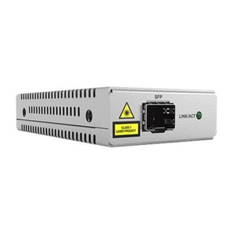
Page 20: Figure 4: At-Umc2000/Sp Front Panel
Chapter 1: Overview Figure 2 illustrates the front panel of the AT-UMC2000/SP Media Converter. Fiber SP SFP Fiber Port Port L/A LED Figure 4. AT-UMC2000/SP Front Panel The UMC2000/200 series media converter Back Panel is shown in Figure Figure 5. UMC2000/200 series media converter Back Panel... -
Page 21: Leds
UMC2000/200 Series Media Converter Installation Guide LEDs The LEDs are located on both the front and rear panel of the UMC2000/200 series media converter. Refer to Figure 1, Figure 2 and Figure 3 on page 19 for the location of the FIBER Link/Activity LED. Figure 5 on page 20 shows the SuperSpeed USB and SYSTEM LED locations. -
Page 22: Reset The Umc Media Converter
Chapter 1: Overview Reset the UMC Media Converter Reset the UMC2000/200 series media converter by powering the unit OFF then powering it back ON. This can be done by unplugging the USB cable from the computer and plugging it back in again. -
Page 23: Chapter 2 : Installation
Chapter 2 Installation This chapter contains the following sections: “Reviewing Safety Precautions” on page 24 “Selecting an Installation Site” on page 26 “Planning the Installation” on page 27 “Unpacking the UMC Media Converter” on page 28 “Installing the UMC Media Converter”... -
Page 24: Reviewing Safety Precautions
available in a PDF document titled Translated Safety Statements on the Allied Telesis website at www.alliedtelesis.com/support. Caution Air vents must not be blocked and must have free access to the room ambient air for cooling. - Page 25 UMC2000/200 Series Media Converter Installation Guide Warning Do not look directly at the fiber-optic cable ends or inspect the cable ends with an optical lens. Warning Laser Safety: EN60825-1. Warning An SFP transceiver can be damaged by static electricity. Be sure to observe all standard electrostatic discharge (ESD) precautions, such as wearing an antistatic wrist strap, to avoid damaging the transceiver.
-
Page 26: Selecting An Installation Site
Chapter 2: Installation Selecting an Installation Site Observe the following requirements when choosing a site for your UMC Media Converter: Verify that the table where you are installing the media converter is level and secure. Air flow around the unit and through its vents on the side should ... -
Page 27: Planning The Installation
UMC2000/200 Series Media Converter Installation Guide Planning the Installation Be sure to observe the following guidelines when planning the installation of your media converter. On the AT-UMC2000 media converter, the end node connected to the fiber port must operate at 1000 Mbps, except the AT-UMC2000/SP model when using a 100Mbps SFP module. -
Page 28: Unpacking The Umc Media Converter
Store the packaging material in a safe location. We recommend that you use the original shipping material if you need to return the unit to Allied Telesis. 2. Place the media converter on a level, secure surface. 3. Verify that the shipping container includes the following items as... -
Page 29: Figure 7: At-Umc2000/Lc Shipping Package Contents
UMC2000/200 Series Media Converter Installation Guide One AT-UMC2000/LC Media Converter One fiber port dust cover (pre-installed) One USB-C to USB-C cable One USB-A to USB-C cable Figure 7. AT-UMC2000/LC Shipping Package Contents One AT-UMC200/ST Media Converter One pair ST fiber port dust cover (pre-installed) One USB-C to USB-C cable... -
Page 30: Figure 9: At-Umc2000/Sp Shipping Package Contents
Chapter 2: Installation One AT-UMC200/ST Media Converter One SFP slot dust cover (pre-installed) One USB-C to USB-C cable One USB-A to USB-C cable Figure 9. AT-UMC2000/SP Shipping Package Contents... -
Page 31: Installing The Umc Media Converter
UMC2000/200 Series Media Converter Installation Guide Installing the UMC Media Converter Desktop When installing the UMC Media Converter on a desktop, place it on a flat, secure surface (such as a desk or table) that is close to your computer. Installation Leave enough space around the unit for ventilation. -
Page 32: Figure 10: Device Manager Window
Chapter 2: Installation 3. Open a Command Window and enter the following command: devmgmt.msc The Device Manager window will open and show an AX88179 device with no driver installed under the “Other devices” icon. Refer to Figure 10. Figure 10. Device Manager Window... -
Page 33: Figure 11: Select "Update Driver Software
UMC2000/200 Series Media Converter Installation Guide 4. Right-click on the AX88179 device and select “Update Driver Software”. Refer to Figure 11. Figure 11. Select “Update Driver Software” The “Update Driver Software” window is displayed. Refer to Figure 12. Figure 12. Update Driver Software Window... -
Page 34: Figure 13: Browse For Driver Software Location
Chapter 2: Installation 5. Select the second option in the Update Driver Software Window - “Browse my computer for driver software”. The Browse option is displayed. Refer to Figure 13. Figure 13. Browse for Driver Software Location 6. Click the Browse button to find the folder containing the drivers. The “Browse for Folder”... -
Page 35: Figure 15: Path Displayed To Umc Driver Folder
UMC2000/200 Series Media Converter Installation Guide 7. Navigate to the folder where you saved the drivers in Step 2 and highlight the folder. Then select the folder by clicking OK. The path to the driver folder is shown in the Browse field. Refer to Figure 15. -
Page 36: Figure 17: Device Manager Window Displaying Umc Device
USB Type-C ...” device driver installed under the “Network Adapters” icon. Refer to Figure 17. Note In order for the Allied Telesis Inc. USB device driver to be displayed in the Device Manager window, the UMC Media Converter must be plugged into the computer’s USB port. -
Page 37: Connecting The Network Cables
UMC2000/200 Series Media Converter Installation Guide Connecting the When the fiber-optic cable is connected to the fiber port of the UMC Media Converter, the fiber connector should fit snugly and be locked into place. Network Cables To connect the network cable, perform the following steps: 1. -
Page 38: Figure 18: Removing The Dust Plug From An Sfp Slot
Chapter 2: Installation Figure 18. Removing the Dust Plug from an SFP Slot 3. Position the SFP transceiver with the label facing up. 4. Slide the transceiver into the SFP slot until it clicks into place. See Figure 19. Figure 19. Inserting the SFP 5. - Page 39 UMC2000/200 Series Media Converter Installation Guide Note SFP transceivers are dust-sensitive. Always keep the plug in the optical bores when a fiber-optic cable is not installed, or when storing the SFP. When you do remove the plug, keep it for future use.
- Page 40 Chapter 2: Installation...
-
Page 41: Chapter 3 : Troubleshooting
Try power cycling the unit by removing the USB cable and re-inserting into the computer’s USB port. If power cycling does not clear the fault, contact Allied Telesis technical support. Problem 2: The SYSTEM LED on the media converter is blinking slowly. - Page 42 Chapter 3: Troubleshooting Verify that the end node connected to the media converter is operating at the same optical wavelength. Make sure the UMC fiber connector and the end node are the same connector type; i.e. SC connected to SC or LC connected to LC. Verify that the transmitter port (TX) is connected to the end node’s ...
-
Page 43: Appendix A: Technical Specifications
Appendix A Technical Specifications Below are the technical specifications for the UMC Media Converters. The specification categories are as follows: “Physical Specifications” “Environmental Specifications” “Power Specifications” on page 44 “Safety and Electromagnetic Emissions Certifications” on page 44 ... -
Page 44: Power Specifications
Appendix A: Technical Specifications Power Specifications The input power specifications given in Table 4 apply to the USB connector on each model of the UMC Media Converter Series. Table 4. Power Specifications Input supply voltage 5 VDC Input current 0.5 A Safety and Electromagnetic Emissions Certifications The safety and electromagnetic emissions certifications of the UMC Media Converter Series are given in Table 5. -
Page 45: Fiber-Optic Port Specifications
UMC2000/200 Series Media Converter Installation Guide Fiber-Optic Port Specifications The fiber type for each model of the UMC Media Converter Series is multimode. The fiber-optic port specifications for the AT-UMC2000 media converter are listed in Table 6 and Table 7. Note Fiber-optic port specifications for the AT-UMC2000/SP depends upon the type of SFP inserted. - Page 46 Appendix A: Technical Specifications...
Need help?
Do you have a question about the UMC2000 Series and is the answer not in the manual?
Questions and answers