Sign In
Upload
Manuals
Brands
Beckhoff Manuals
Industrial PC
CX2000 Series
Beckhoff CX2000 Series Manuals
Manuals and User Guides for Beckhoff CX2000 Series. We have
2
Beckhoff CX2000 Series manuals available for free PDF download: Manual
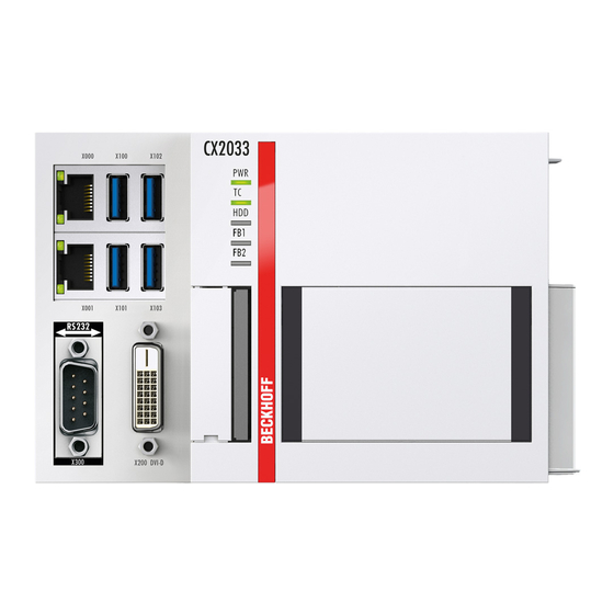
Beckhoff CX2000 Series Manual (92 pages)
Embedded
Brand:
Beckhoff
| Category:
Industrial PC
| Size: 12 MB
Table of Contents
Table of Contents
3
Notes on the Documentation
7
Representation and Structure of Warnings
8
Related Documents
9
Documentation Issue Status
9
For Your Safety
10
Intended Use
10
Staff Qualification
10
Safety Instructions
11
Notes on Information Security
11
Transport and Storage
13
Table 1 Dimensions and Weight of the Individual Modules
13
Product Overview
14
Fig. 1 Overview of the CX2000 Product Family with Basic CPU Module, Power Supply Unit and Mod- Ules
14
Table 2 Available Optional Interfaces for the Cx20X0
15
Configuration of the Basic CPU Module
16
Table 3 Legend for the Configuration of the Basic CPU Module
16
Fig. 2 Example: Embedded Pcs CX2040 with Active Cooling
16
Fig. 3 Name Plate Example
17
Table 4 Information on the Name Plate
17
Name Plate
17
Types
17
Table 5 Cx20X0, Ordering Information for Software
18
Fig. 4 Nomenclature for the Basic CPU Module
18
Architekture Overview
19
Fig. 5 Cx20X0 Architecture Overview
19
Table 6 USB Interfaces (X100, X101, X102, X103), Pin Assignment
21
Fig. 6 USB Interfaces (X100, X101, X102, X103)
21
Usb (X100, X101, X102, X103)
21
Interface Description
21
Ethernet RJ45 (X000, X001)
22
Table 7 Ethernet Interface X000 and X001, Pin Assignment
22
Fig. 7 Ethernet Interfaces X000, X001
22
DVI-I (X200)
23
Table 8 DVI-I Interface X200, Pin Assignment
23
Table 9 DVI-I Cross, Pin Assignment
23
Table 10 DVI-I Interface X200, Resolution at the Monitor
23
Fig. 8 DVI-I Interface X200
23
Table 12 DVI-D Interface X300, Resolution at the Monitor
24
Fig. 9 DVI-D Interface X300
24
Table 11 DVI-D Interface X300, Pin Assignment
24
DVI-D (N010)
24
Optional Interfaces
24
Displayport (N011)
25
Table 13 Displayport, Pin Assignment
25
Table 14 Displayport X300, Resolution at the Monitor
25
Fig. 10 Displayport X300
25
Rs232 (N030)
26
Table 15 RS232 Interface X300, Pin Assignment
26
Fig. 11 RS232 Interface X300
26
Fig. 12 RS485 Interface X300
27
Table 16 RS422/485 Interface, Pin Assignment
27
Table 17 Default Setting, RS485 Without Echo with End Point (Terminated)
27
Rs422/Rs485 (N031)
27
Ethercat Slave (B110)
28
Table 18 Ethercat Slave Interface X300, Pin Assignment
28
Fig. 13 Ethercat Slave Interface X300
28
PROFIBUS (X310)
29
Table 19 PROFIBUS Interface X310, Pin Assignment
29
Table 20 Wire Colors of the PROFIBUS Line
29
Fig. 14 PROFIBUS Interface X310
29
Fig. 15 Canopen Interface X510
30
Table 21 Canopen Interface X510, Pin Assignment
30
Canopen (X510)
30
Table 22 PROFINET RT Interface, Pin Assignment
31
Fig. 16 PROFINET RT Interface X300
31
PROFINET RT (X930)
31
Commissioning
32
Selecting the Appropriate CX2100 Power Supply Unit
32
Table 23 Power Supply Units for Horizontal Installation Position
32
Table 24 Power Supply Units for Vertical Installation Position
32
Fig. 17 Embedded Pccx20X0With Power Supply Unit CX2100-0014, Configuration of the Power Supply Terminal
32
Table 25 Legend for Configuration of the Power Supply Terminal
33
Fig. 19 CX2040 Embedded PC, Dimensions
34
Mounting
34
Fig. 18 CX2020 and CX2030 Embedded PC, Dimensions
34
Attaching the Power Supply Unit
35
Installing the Bar Clips
35
Note the Permissible Installation Positions
36
Table 26 Embedded PC Cx20X0, Installation Position Depending on the Cooling Option
36
Fig. 20 Embedded PC Cx20X0, Horizontal Installation Position
36
Attaching on Mounting Rail
38
Cfast Card Installation and Removal
39
Fig. 22 Passive Ethercat Terminals, Permissible Installation
40
Fig. 21 Identifying a Passive Ethercat Terminal in Twincat
40
Installing Passive Ethercat Terminals
40
Power Supply
41
Table 27 Legend for the Connection Example
41
Fig. 23 Connections for System Voltage (Us) and Power Contacts (Up)
41
Connect Embedded PC
42
UL Requirements
42
Table 28 Required Conductor Cross-Sections and Strip Lengths
42
Fig. 24 Connection Example with a Cx20X0
42
Fig. 26 Connection Example for Areas with Special UL Requirements
43
Fig. 25 UL Label for Cx20X0
43
Switching on
43
Switching off
44
Configuration
45
Windows Embedded Compact 7
45
Scan for New Hardware
45
Windows Embedded Standard 7 P
46
Identification of the Ethernet Interfaces (X000, X001)
46
Fig. 27 Windows 7, Identification of the Ethernet Interfaces (X000, X001) in the Network and Sharing Center
46
Fig. 28 Windows 7, Identification of the Ethernet Interfaces (X000, X001) in the Device Manager
46
Enabling Jumbo Frames
47
Set NIC Teaming
48
Restoring the Beckhoff Real-Time Driver
50
Windows 10 Iot Enterprise LTSB
51
Identification of the Ethernet Interfaces (X000, X001)
51
Fig. 29 Windows 10, Identification of the Ethernet Interfaces (X000, X001) in the Network and Sharing Center
51
Fig. 30 Windows 10, Identification of the Ethernet Interfaces (X000, X001) in the Device Manager
51
Beckhoff Device Manager
52
Starting the Beckhoff Device Manager
52
Table 29 Access Data for the Beckhoff Device Manager on Delivery
52
Enabling a Remote Display
53
Table 30 Access Data for the Beckhoff Device Manager on Delivery
53
Starting a Remote Connection
54
Twincat
55
Tree View
55
Table 31 Legend for the Tree View
55
Fig. 31 Cx20X0 Embedded PC in the Tree View of Twincat 3, with Attached Ethercat Terminals (Left) or Bus Terminals (Right)
55
Searching for Target Systems
56
Scanning an Embedded PC
58
Configuring Ethercat Cable Redundancy
59
Table 32 Cable Redundancy, Hardware for Sample Configuration
59
Fig. 32 Smallest Possible Configuration for Ethercat Cable Redundancy
59
Using a Hardware Watchdog
62
Novram
63
Fig. 33 Controller Behavior with and Without NOVRAM
63
Creating a Retain Handler
64
Creating and Linking Variables
66
Writing Speed of the Retain Handler
68
Fig. 34 Retain Handler Write Speed, up to 63 Kb in 512 Byte Steps
68
Fig. 35 Retain Handler Write Speed, up to 8 Kb in 64 Byte Steps
68
Deleting Variables under the Retain Handler
69
UPS (Persistent Data)
70
Plcappsysteminfo
71
Checking the Validity of the Variables
71
Windows Write Filter
71
Error Handling and Diagnostics
73
Diagnostic Leds
73
K-Bus
73
Table 33 Diagnostic Leds in K-Bus Mode
73
Table 34 K-Bus ERR LED, Fault Indication Sequence through the LED
73
Table 35 K-BUS ERR LED, Fault Description and Troubleshooting
74
Table 36 Description of the State Variable Values
75
Fig. 36 Status Variable for Error Handling and Diagnostics under Twincat
75
E-Bus
76
Table 37 Diagnostic Leds in K-Bus Mode
76
Table 38 Possible Faults and Their Correction
77
Faults
77
Care and Maintenance
78
Replace the Battery
78
Replace the Fan Cartridge
78
Table 39 in the Cx20X0 the Fan Control and Speed Depend on the Temperature
79
Decommissioning
80
Removing Cables
80
Dismantling the Embedded PC
80
Table 42 Technical Data, I/O Terminals
83
Technical Data
83
Table 41 Technical Data, General Data
83
Table 40 Technical Data, Dimensions and Weights
83
Table 43 Technical Data, Environmental Conditions
84
Table 44 Technical Data, Graphic Specifications
84
Appendix
85
Accessories
85
Certifications
86
Support and Service
87
List of Tables
88
Advertisement
Beckhoff CX2000 Series Manual (79 pages)
Embedded PC
Brand:
Beckhoff
| Category:
Industrial PC
| Size: 19 MB
Table of Contents
Table of Contents
3
1 Notes on the Documentation
5
Representation and Structure of Warnings
6
Documentation Issue Status
7
2 For Your Safety
8
Intended Use
8
Staff Qualification
8
Safety Instructions
8
3 Transport and Storage
10
Table 1 Dimensions and Weight of the Individual Modules
10
4 Product Overview
11
Table 2 Available Extension Modules for the Cx20X3
11
Table 3 Available Optional Interfaces for the Cx20X3
12
Structure
13
Table 4 Legend for the Configuration of the Basic CPU Module
13
Fig. 1 Example: Embedded Pcs CX2043 with Active Cooling
13
Name Plate
14
Table 5 Information on the Name Plate
14
Fig. 2 Name Plate Example
14
Types
15
Table 6 Cx20X3 Ordering Information
15
Fig. 3 Nomenclature for the Basic CPU Module
15
Architekture Overview
16
5 Interface Description
17
Usb 3.1 (X100, X101, X102, X103)
17
Table 7 USB Interfaces (X100, X101, X102, X103), Pin Assignment
17
Fig. 4 USB Interfaces (X100, X101, X102, X103)
17
Ethernet RJ45 (X000, X001)
18
Table 8 Ethernet Interface X000 and X001, Pin Assignment
18
Fig. 5 Ethernet Interfaces X000, X001
18
DVI-D (X200)
19
Table 9 DVI-D Interface X200, Pin Assignment
19
Table 10 DVI-D Interface X200, Resolution at the Monitor
19
Fig. 6 DVI-D Interface X200
19
Optional Interfaces
20
DVI-D (N010)
20
Table 11 DVI-D Interface X300, Pin Assignment
20
Table 12 DVI-D Interface X300, Resolution at the Monitor
20
Fig. 7 DVI-D Interface X300
20
Displayport (N011)
21
Table 13 Displayport, Pin Assignment
21
Table 14 Displayport X300, Resolution at the Monitor
21
Fig. 8 Displayport X300
21
Rs232 (N030)
22
Table 15 RS232 Interface X300, Pin Assignment
22
Fig. 9 RS232 Interface X300
22
Rs422/Rs485 (N031)
23
Table 16 RS422/485 Interface, Pin Assignment
23
Table 17 Default Setting, RS485 Without Echo with End Point (Terminated)
23
Fig. 10 RS485 Interface X300
23
Ethercat Slave (B110)
24
Table 18 Ethercat Slave Interface X300, Pin Assignment
24
Fig. 11 Ethercat Slave Interface X300
24
PROFIBUS (X310)
25
Table 19 PROFIBUS Interface X310, Pin Assignment
25
Table 20 Wire Colors of the PROFIBUS Line
25
Fig. 12 PROFIBUS Interface X310
25
Canopen (X510)
26
Table 21 Canopen Interface X510, Pin Assignment
26
Fig. 13 Canopen Interface X510
26
PROFINET RT (X930)
27
Table 22 PROFINET RT Interface, Pin Assignment
27
Fig. 14 PROFINET RT Interface X300
27
6 Commissioning
28
Selecting the Appropriate CX2100 Power Supply Unit
28
Table 23 Suitable Power Supply Unit for the Cx20X3 Embedded PC
28
Table 24 Legend for Configuration of the Power Supply Terminal
28
Fig. 15 Embedded PC CX2043 with Power Supply Unit CX2100-0014, Configuration of the Power Sup- Ply Terminal
28
Mounting
29
Fig. 16 CX2033 Embedded PC, Dimensions
29
Fig. 17 CX2043 Embedded PC, Dimensions
29
Attaching the Power Supply Unit
30
Installing the Bar Clips
30
Note the Permissible Installation Positions
31
Table 25 Embedded PC Cx20X3, Installation Position Depending on the Cooling Option
31
Fig. 18 Embedded PC Cx20X3, Horizontal Installation Position
31
Attaching on Mounting Rail
33
Cfast Card Installation and Removal
34
Installing Passive Ethercat Terminals
35
Fig. 19 Identifying a Passive Ethercat Terminal in Twincat
35
Fig. 20 Passive Ethercat Terminals, Permissible Installation
35
Power Supply
36
Table 26 Legend for the Connection Example
36
Fig. 21 Connections for System Voltage (Us) and Power Contacts (Up)
36
Connect Embedded PC
37
Table 27 Required Wire Cross-Sections and Strip Lengths
37
Fig. 22 Connection Example with a CX2033
37
Switching on
38
Switching off
38
7 Configuration
39
Starting the Beckhoff Device Manager
39
Table 28 Access Data for the Beckhoff Device Manager on Delivery
39
Windows 10 Iot Enterprise
40
Enabling Jumbo Frames
40
Set NIC Teaming
41
Restoring the Beckhoff Real-Time Driver
43
Twincat
44
Tree View
44
Table 29 Legend for the Tree View
44
Fig. 23 Cx20X0 Embedded PC in the Tree View of Twincat 3, with Attached Ethercat Terminals (Left) or Bus Terminals (Right)
44
Searching for Target Systems
45
Scanning an Embedded PC
47
Configuring Ethercat Cable Redundancy
48
Table 30 Cable Redundancy, Hardware for Sample Configuration
48
Fig. 24 Example Configuration of a Cx20X3 with Ethercat Cable Redundancy
48
Using a Hardware Watchdog
51
8 Novram
52
Fig. 25 Controller Behavior with and Without NOVRAM
52
Creating a Retain Handler
53
Creating and Linking Variables
55
Writing Speed of the Retain Handler
57
Fig. 26 Retain Handler Write Speed, up to 63 Kb in 512 Byte Steps
57
Fig. 27 Retain Handler Write Speed, up to 8 Kb in 64 Byte Steps
57
Deleting Variables under the Retain Handler
58
9 Error Handling and Diagnostics
59
Diagnostic Leds
59
K-Bus
59
Table 31 Diagnostic Leds in K-Bus Mode
59
Table 32 K-Bus ERR LED, Fault Indication Sequence through the LED
59
Table 33 K-BUS ERR LED, Fault Description and Troubleshooting
60
Table 34 Description of the State Variable Values
61
Fig. 28 Status Variable for Error Handling and Diagnostics under Twincat
61
E-Bus
62
Table 35 Diagnostic Leds in K-Bus Mode
62
Faults
63
Table 36 Possible Faults and Their Correction
63
10 Care and Maintenance
64
Replace the Battery
64
Replace the Fan Cartridge
66
Table 37 in the Cx20X3 the Fan Control and Speed Depend on the Temperature
66
Cleaning the Embedded PC
67
11 Decommissioning
68
Removing Cables
68
Dismantling the Embedded PC
69
12 Technical Data
70
Table 38 Technical Data, Dimensions and Weights
70
Table 39 Technical Data, General Data
70
Table 40 Technical Data, I/O Terminals
70
Table 41 Technical Data, Environmental Conditions
70
Table 42 Technical Data, Graphic Specifications
71
Table 43 Technical Data, Interfaces
71
Table 44 Technical Data, Optional Interfaces
71
13 Appendix
72
Accessories
72
Certifications
73
Support and Service
74
List of Tables
75
Advertisement
Related Products
Beckhoff CX20 3 Series
Beckhoff CX2043
Beckhoff CX2033
Beckhoff CX20 0 Series
Beckhoff CX2020
Beckhoff CX2030
Beckhoff CX2040
Beckhoff CX2500-0060
Beckhoff CX2500-B510
Beckhoff CX2500-M510
Beckhoff Categories
Touch terminals
Industrial PC
Control Unit
Industrial Equipment
Control Panel
More Beckhoff Manuals
Login
Sign In
OR
Sign in with Facebook
Sign in with Google
Upload manual
Upload from disk
Upload from URL