Table of Contents
Advertisement
Advertisement
Chapters
Table of Contents

Related Manuals for Beckhoff CX2000 Series


Summary of Contents for Beckhoff CX2000 Series
- Page 1 Manual | EN CX20x3 Embedded PC 1/14/2021 | Version: 1.0...
-
Page 3: Table Of Contents
Installing passive EtherCAT Terminals................ 35 Power supply ........................... 36 6.3.1 Connect Embedded PC .................... 37 Switching on ............................ 38 Switching off ............................ 38 7 Configuration ............................ 39 Starting the Beckhoff Device Manager .................... 39 Windows 10 IoT Enterprise ...................... 40 7.2.1 Enabling jumbo frames .................... 40 CX20x3 Version: 1.0... - Page 4 Table of contents 7.2.2 Set NIC Teaming ...................... 41 7.2.3 Restoring the Beckhoff real-time driver ................ 43 TwinCAT ............................ 44 7.3.1 Tree view ......................... 44 7.3.2 Searching for target systems ................... 45 7.3.3 Scanning an Embedded PC .................... 47 7.3.4 Configuring EtherCAT cable redundancy................ 48 7.3.5...
-
Page 5: Notes On The Documentation
EP1590927, EP1789857, EP1456722, EP2137893, DE102015105702 with corresponding applications or registrations in various other countries. ® EtherCAT is a registered trademark and patented technology, licensed by Beckhoff Automation GmbH, Germany Copyright © Beckhoff Automation GmbH & Co. KG, Germany. The reproduction, distribution and utilization of this document as well as the communication of its contents to others without express authorization are prohibited. -
Page 6: Representation And Structure Of Warnings
Notes on the documentation Representation and structure of warnings The following warnings are used in the documentation. Read and follow the warnings. Warnings relating to personal injury: DANGER Hazard with high risk of death or serious injury. WARNING Hazard with medium risk of death or serious injury. CAUTION There is a low-risk hazard that can result in minor injury. -
Page 7: Documentation Issue Status
Notes on the documentation Documentation issue status Version Modifications First version CX20x3 Version: 1.0... -
Page 8: For Your Safety
Beckhoff Automation GmbH & Co. In addition, the following actions are excluded from the liability of Beckhoff Automation GmbH & Co. KG: • Failure to comply with this documentation. - Page 9 • The sensitivity of a PC against malicious software increases with the number of installed and active software. • Uninstall or disable unnecessary software. Further information about the safe handling of networks and software can be found in the Beckhoff Information System: http://infosys.beckhoff.com...
-
Page 10: Transport And Storage
Transport and storage Transport and storage Transport NOTE Short circuit due to moisture Moisture can form during transport in cold weather or in the event of large temperature fluctuations. Avoid moisture formation (condensation) in the Embedded PC, and leave it to adjust to room temperature slowly. -
Page 11: Product Overview
Product overview Product overview The CX2000 product family consists of individual modules, which can be assembled to form a customized Embedded PC. The CX2000 product family consists of: • basic CPU modules, • CX2100 power supply units, • system, fieldbus and extension modules. Basic CPU module The basic CPU module is a fully functional PC and can be used in conjunction with a CX2100 power supply unit as the smallest possible configuration. -
Page 12: Table 3 Available Optional Interfaces For The Cx20X3
Product overview Optional interface The basic CPU module can be ordered ex factory with an optional interface. The optional interface cannot be retrofitted. Table 3: Available optional interfaces for the CX20x3. CX20x3-xxxx Optional interfaces CX20x3-N010 DVI-D, additional DVI-D socket for clone and extended display mode. CX20x3-N011 DisplayPort, additional DisplayPort for clone and extended display mode CX20x3-N030 RS232, D-sub connector, 9-pin. -
Page 13: Structure
Product overview Structure Fig. 1: Example: Embedded PCs CX2043 with active cooling. Table 4: Legend for the configuration of the basic CPU module Component Description Multi-pin connection (left) Extension through system modules and fieldbus modules of type CX2500. Optional interface (X300). Space for interfaces such as RS232, EtherCAT, CANopen or others. -
Page 14: Name Plate
Embedded PC, operating system, options and TwinCAT can be reordered. Product designation for identification of the Embedded PC Serial number/ Beckhoff Traceability Number (BTN) for the unambiguous identification of the product. Hardware version and date of manufacture. -
Page 15: Types
Product overview Types The basic CPU module can be ordered with different hardware and software options. Use this overview in conjunction with the information on the name plate to ascertain the hardware, operating system and TwinCAT version of the basic CPU module. Fig. 3: Nomenclature for the basic CPU module. -
Page 16: Architekture Overview
Product overview Architekture overview The Embedded PCs of the CX20x3 family all have the same architecture. The CX20x3 Embedded PCs are based on the AMD Zen microarchitecture. The following CPUs are used: • AMD Ryzen™ V1202B (dual core), • AMD Ryzen™ V1807B (quad core), In addition to the arithmetic unit, the CPU also contains the memory controller and the graphics controller. -
Page 17: Interface Description
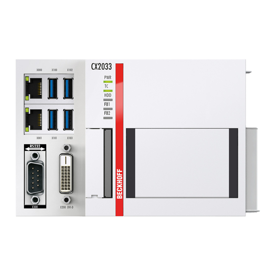
Interface description Interface description USB 3.1 (X100, X101, X102, X103) The Embedded PC has four independent USB interfaces. for connecting keyboards, mice, touchscreens and other input or data storage devices. Fig. 4: USB interfaces (X100, X101, X102, X103). The USB interfaces are type A and comply with the USB 3.1 Gen. 1 specification. Table 7: USB interfaces (X100, X101, X102, X103), pin assignment. -
Page 18: Ethernet Rj45 (X000, X001)
Interface description Ethernet RJ45 (X000, X001) The two Ethernet interfaces are independent; no switch is integrated. The independent Ethernet interfaces can be configured in different ways. In the delivery state, the Ethernet interfaces (X000, X001) are configured for EtherCAT communication. Note that an additional switch is required for a line topology. -
Page 19: Dvi-D (X200)
N010 interface (DVI-D interface) is used, the first DVI-I interface can be operated either in VGA mode or in DVI mode. The resolution at the display or the Beckhoff Control Panel depends on the distance from the display device. The maximum distance is 5 m. Beckhoff offers various Panels with an integrated “DVI extension”. -
Page 20: Optional Interfaces
N010 interface (DVI-D interface) is used, the first DVI-I interface can be operated either in VGA mode or in DVI mode. The resolution at the display or the Beckhoff Control Panel depends on the distance from the display device. The maximum distance is 5 m. Beckhoff offers various Panels with an integrated “DVI extension”. -
Page 21: Displayport (N011)
Interface description 5.4.2 DisplayPort (N011) The DisplayPort transfers image and audio signal at the same time and is therefore suitable for connecting panels or monitors to the Embedded PC. Fig. 8: DisplayPort X300. Version 1.1a of the DisplayPort (DisplayPort++) is installed on the Embedded PC. Adapters from DisplayPort to DVI-D or DisplayPort to HDMI can be used to connect monitors without DisplayPort to the Embedded PC. -
Page 22: Rs232 (N030)
Interface description 5.4.3 RS232 (N030) The optional N030 interface provides an RS232 interface (X300). The RS232 interface is implemented on a 9-pin D-sub connector. Fig. 9: RS232 interface X300. The maximum baud rate on both channels is 115 kbit. The interface parameters are set via the operating system or from the PLC program. -
Page 23: Rs422/Rs485 (N031)
Interface description 5.4.4 RS422/RS485 (N031) The optional N031 interface provides an RS422 or RS485 interface (X300). The interface is executed on a 9- pin D-sub socket. Fig. 10: RS485 interface X300. The maximum baud rate on both channels is 115 kbit. The interface parameters are set via the operating system or from the PLC program. -
Page 24: Ethercat Slave (B110)
Receive + connected reserved RD - Receive - connected reserved For the optional EtherCAT slave interface (B110), documentation with further information is available for download from the Beckhoff website: https://www.beckhoff.de/german/download/epc.htm?id=71003127100362 Document name CXxxx0-B110 optional interface EtherCAT slave. Version: 1.0 CX20x3... -
Page 25: Profibus (X310)
PROFIBUS line D sub B red Pin 3 A green Pin 8 For the optional PROFIBUS interface (x310), documentation with further information is available for download from the Beckhoff website: https://www.beckhoff.de/german/download/epc.htm?id=71003127100362 Document name CXxxx0-x310 optional Profibus interface. CX20x3 Version: 1.0... -
Page 26: Canopen (X510)
CAN Ground (internally connected to pin 3) CAN high (CAN+) not used not used For the optional CANopen interface (x510), documentation with further information is available for download from the Beckhoff website: https://www.beckhoff.de/german/download/epc.htm?id=71003127100362 Document name CXxxx0-x510 optional CANopen interface. Version: 1.0... -
Page 27: Profinet Rt (X930)
Interface description 5.4.8 PROFINET RT (x930) Fig. 14: PROFINET RT interface X300. Table 22: PROFINET RT interface, pin assignment. Signal Description TD + Transmit + TD - Transmit - RD + Receive + connected reserved RD - Receive - connected reserved CX20x3 Version: 1.0... -
Page 28: Commissioning
Commissioning Commissioning Selecting the appropriate CX2100 power supply unit The basic CPU module requires a power supply unit of type CX2100-0xxx. Connect the power supply unit to the multi-pin port on the right of the basic CPU module. Table 23: Suitable power supply unit for the CX20x3 Embedded PC. Basic CPU module Power supply units CX2033... -
Page 29: Mounting
Commissioning Mounting Fig. 16: CX2033 Embedded PC, dimensions. Fig. 17: CX2043 Embedded PC, dimensions. CX20x3 Version: 1.0... -
Page 30: Attaching The Power Supply Unit
Commissioning 6.2.1 Attaching the power supply unit The basic CPU module requires a power supply unit of type CX2100-0xxx. Connect the power supply unit to the multi-pin port on the right of the basic CPU module. Proceed as follows: 1. Select the appropriate power supply unit, as described in chapter Selecting the appropriate CX2100 power supply unit [} 28]. -
Page 31: Note The Permissible Installation Positions
Commissioning 6.2.3 Note the permissible installation positions NOTE Overheating The Embedded PC may overheat if the installation position is incorrect or the minimum distances are not adhered to. Adhere to the maximum ambient temperature of 60°C and the mounting instructions. Install the Embedded PC horizontally in the control cabinet on a mounting rail, in order to ensure optimum heat dissipation. - Page 32 Commissioning Permitted installation positions with fan Only Embedded PCs with an active cooling can be installed vertically or horizontally on the mounting rail. Without active cooling the Embedded PC is not ventilated adequately in vertical or horizontal position. Even with active cooling, the ambient temperature range between -25 and 60 °C and the minimum distances of 30 mm above and below the Embedded PC should be adhered to.
-
Page 33: Attaching On Mounting Rail
Commissioning 6.2.4 Attaching on mounting rail The housing is designed such that the Embedded PC can be pushed against the mounting rail and latched onto it. Requirements: • Mounting rail of type TS35/7.5 or TS35/15 according to DIN EN 60715. Secure the Embedded PC on the mounting rail as follows: 1. -
Page 34: Cfast Card Installation And Removal
A CFast card is a non-volatile memory. Data to be retained in the event of a power failure should be saved on the CFast card. The CFast cards supplied by Beckhoff are industrial cards with an increased number of write cycles and an extended temperature range (+85 °C). -
Page 35: Installing Passive Ethercat Terminals
Commissioning 6.2.6 Installing passive EtherCAT Terminals Incorrectly installed passive EtherCAT Terminals The E-bus signal between an Embedded PC and the EtherCAT Terminals can be impaired due to incorrectly installed passive EtherCAT Terminals. Passive EtherCAT Terminals should not be installed directly on the power supply unit. EtherCAT Terminals that do not take part in active data exchange are referred to as passive terminals. -
Page 36: Power Supply
Commissioning Power supply NOTE Damage to the Embedded PCs The Embedded PCs may be damaged during wiring. The cables for the power supply should only be con- nected in de-energized state. The power supply units require an external voltage source, which provides 24 V DC (-15% /+20%). The cabling of the Embedded PC in the control cabinet must be done in accordance with the standard EN 60204-1:2006 PELV = Protective Extra Low Voltage: •... -
Page 37: Connect Embedded Pc
Commissioning 6.3.1 Connect Embedded PC The cables of an external voltage source are connected to the power supply unit with spring-loaded terminals. Observe the required conductor cross-sections and strip lengths. Table 27: Required wire cross-sections and strip lengths. Conductor cross-section 0.5 ... 2.5 mm AWG 20 ... -
Page 38: Switching On
Commissioning Switching on Please ensure that the Embedded PC is fully configured before switching on the Embedded PC. Switch on the Embedded PC as follows: 1. Ensure that all extension, system and fieldbus modules are connected correctly. 2. Check whether the right CX2100 power supply unit and the right installation position were selected. 3. -
Page 39: Configuration
Start the Beckhoff Device Manager as follows: 1. Open a web browser on the host PC. 2. Enter the IP address or the host name of the Industrial PC in the web browser to start the Beckhoff Device Manager. • Example with IP address: https://169.254.136.237/config •... -
Page 40: Windows 10 Iot Enterprise
Requirements: • The original Intel® driver can be downloaded from https://downloadcenter.intel.com. • Install the original Intel® driver. Note that this will delete the real-time capable driver from Beckhoff. • Check whether the peripheral devices support jumbo frames. Jumbo frames are activated as follows: 1. -
Page 41: Set Nic Teaming
• The original Intel® driver can be downloaded from https://downloadcenter.intel.com. • Install the original Intel® driver for the Network Interface Card. Note that this will delete the real-time capable driver from Beckhoff. NIC Teaming is set as follows: 1. Under Start > Control Panel > Hardware and Sound click on Device Manager. - Page 42 Configuration 5. Under Select a team type select the option Adapter Fault Tolerance 6. Click on Next to complete the installation. ð You have successful set NIC Teaming for your Ethernet interfaces. Further settings can be specified or changed under the Settings tab. Version: 1.0 CX20x3...
-
Page 43: Restoring The Beckhoff Real-Time Driver
The installation dialog appears and shows the compatible Ethernet interfaces under Compatible devices. 2. Select the Ethernet interfaces for which you wish to restore the Beckhoff real-time driver and click on Install. ð The Beckhoff real-time driver is installed. The Ethernet interfaces with installed Beckhoff real-time driver are shown under Installed and ready to use devices (real-time capable). -
Page 44: Twincat
Configuration TwinCAT 7.3.1 Tree view The Tree View chapter can be used as an example for creating a project without actual hardware. All devices and components of an Embedded PCs must be added manually in TwinCAT 3. The smallest possible configuration of a CX20x0 Embedded PC, consisting of a basic CPU module and a CX2100-0004 power supply unit, is displayed in the tree view of TwinCAT 3 as follows: Fig. 23: CX20x0 Embedded PC in the tree view of TwinCAT 3, with attached EtherCAT Terminals (left) or Bus Terminals (right). -
Page 45: Searching For Target Systems
Configuration 7.3.2 Searching for target systems Before you can work with the devices, you must connect your local computer to the target device. Then you can search for devices with the help of the IP address or the host name. The local PC and the target devices must be connected to the same network or directly to each other via an Ethernet cable. - Page 46 Configuration Enter the user name and password for the CX in the User Name and Password fields and click OK. The following information is set as standard in CX devices: User name: Administrator Password: 1 6. If you do not wish to search for any further devices, click on Close to close the Add Route Dialog. The new device is displayed in the Choose Target System window.
-
Page 47: Scanning An Embedded Pc
Configuration 7.3.3 Scanning an Embedded PC This step shows how to scan an Embedded PC in TwinCAT and then further configure it. Prerequisites for this step: • Selected target device. Add the Embedded PC as follows: 1. Start TwinCAT and open an empty project. 2. -
Page 48: Configuring Ethercat Cable Redundancy
Requirements: • For TwinCAT 2 you have to install and license the supplement TS622x | TwinCAT EtherCAT Redundancy on the Embedded PC: http://www.beckhoff.de/forms/twincat3/warenkorb.aspx?lg=de&title=TS622x-EtherCAT- Redundancy&version=1.0.2 • In TwinCAT 3 the supplement is already included and only has to be licensed. • Hardware wired as EtherCAT ring (see Fig.: Smallest possible configuration for EtherCAT cable redundancy) and added in TwinCAT. - Page 49 Configuration 1. In the tree view click on the EtherCAT master. 2. Click on the EtherCAT tab, then Advanced Settings. 3. Click on Redundancy in the tree structure on the left. 4. Click on the option Second adapter, followed by the Search button. CX20x3 Version: 1.0...
- Page 50 Configuration 5. Select the appropriate LAN connection according to your cabling at the Embedded PC. 6. Confirm the settings with OK. ð You have successfully configured cable redundancy. Under the Online tab the EtherCAT slaves are displayed, for which cable redundancy was configured. Under State the state of the individual EtherCAT slaves is displayed.
-
Page 51: Using A Hardware Watchdog
Configuration 7.3.5 Using a hardware watchdog The function block FB_PcWatchdog_BAPI activates a hardware watchdog on the Embedded PC. The watchdog can be used to automatically restart systems that have entered an infinite loop or where the PLC has stopped. The watchdog is activated with bExecute = TRUE and nWatchdogTimeS >= 1s. Once the watchdog has been activated, the function block must be called cyclically and at shorter intervals than nWatchdogTimeS, because the Embedded PC automatically restarts if the set time is less than nWatchdogTimeS. -
Page 52: Novram
NOVRAM NOVRAM The NOVRAM can be used to reliably save important variable values, such as production data or counter values, in the event of a power failure. The memory size of the NOVRAM is limited and only suitable for smaller data quantities up to 63 kB. In this chapter we show you how the NOVRAM is used in TwinCAT 3. -
Page 53: Creating A Retain Handler
NOVRAM Creating a Retain Handler Under TwinCAT 3 (from Build 4020) a delta algorithm is used to save data in the NOVRAM. The algorithm does not save all the variables in the NOVRAM. Instead, it searches for changes (delta function) compared to the previous cycle and only saves variables that have changed. - Page 54 NOVRAM 5. Click on Device (NOV-DP-RAM) in the tree view on the left-hand side and then on the tab Generic NOV-DP-RAM Device. 6. Click the option PCI. 7. Right-click on Device (NOV-DP-RAM) in the tree view and then on Add New Item. 8.
-
Page 55: Creating And Linking Variables
NOVRAM Creating and linking variables Once you have created a Retain Handler in TwinCAT, you can declare variables in the PLC and link them to the Retain Handler. The variables have to be identified in the PLC with the keyword VAR_RETAIN. Prerequisite for this step: •... - Page 56 NOVRAM 4. Under Retain Hdl, select the Retain Handler that you have created. ð After selecting a Retain Handler as a target, the symbols in the tree view are linked and a mapping is created. In the tree view the variables are created from the PLC under the Retain Handler and linked to the variables from the PLC instance.
-
Page 57: Writing Speed Of The Retain Handler
NOVRAM Writing speed of the Retain Handler The Retain Handler takes a certain amount of time to search for changes (delta function) in the variables and save them in the NOVRAM. The following diagrams provide an overview of how long the Retain Handler needs to save a particular data quantity in the NOVRAM. -
Page 58: Deleting Variables Under The Retain Handler
NOVRAM Deleting variables under the Retain Handler If variables are deleted from the PLC, the link with the Retain Handler is cancelled. However, the variables continue to be shown under the Retain Handler and are not deleted automatically. Under TwinCAT 3 the variables have to be deleted manually. Prerequisites for this step: •... -
Page 59: Error Handling And Diagnostics
Error handling and diagnostics Error handling and diagnostics Diagnostic LEDs Display Meaning Power supply The Power LED comes on (green) when the device is connected to a live power supply unit. Die SUPS is active (violet). Bootloader is started and runs without errors (the colors red and yellow light up for one second). -
Page 60: Table 33 K-Bus Err Led, Fault Description And Troubleshooting
Error handling and diagnostics Table 33: K-BUS ERR LED, fault description and troubleshooting. Error code Error code argu- Description Remedy ment Persistent, EMC problems. • Check power supply for undervoltage or continuous overvoltage peaks. flashing • Implement EMC measures. • If a K-bus error is present, it can be localized by a restart of the power supply (by switching it off and then on again) 3 pulses... -
Page 61: Table 34 Description Of The State Variable Values
Error handling and diagnostics State variable In TwinCAT there is a State variable under the Bus Coupler for K-bus diagnostics. Fig. 28: Status variable for error handling and diagnostics under TwinCAT. If the value is "0", the K-bus operates synchronous and without error. If the value is <> "0" there may be a fault, or it may only be an indication that the K-bus cycle is longer than the task. -
Page 62: E-Bus
Error handling and diagnostics 9.1.2 E-bus The power supply unit checks the connected EtherCAT Terminals. The "L/A" LED is lit in E-bus mode. The "L/A" LED flashes during data transfer. Table 35: Diagnostic LEDs in K-Bus mode. Display Meaning Us 24 V Power supply for basic CPU module. -
Page 63: Faults
Settings" on the CFast card. hardware (e.g. extension modules). first startup. See: Scan for new hardware Please make a note of the following information before contacting Beckhoff service or support: 1. Precise device ID: CXxxxx-xxxx. 2. Serial number. 3. Hardware version. -
Page 64: Care And Maintenance
Only use original batteries and ensure that the positive and negative poles are inserted correctly. The battery must be replaced every 5 years. Spare batteries can be ordered from Beckhoff Service. A CR2032 battery (3 V, 225 mAh) is used in the Embedded PC. - Page 65 Care and maintenance 2. Carefully pull the battery from the bracket. 3. Push the new battery into the battery compartment. The positive pole points to the left towards the DVI-I interface. ð The battery change is complete. Close the front flap and reset the date and time in the BIOS. CX20x3 Version: 1.0...
-
Page 66: Replace The Fan Cartridge
100% 5900 rpm Use the IPC diagnostics and monitor the fan speed to determine a fan fault. Access to the fan status is described in the documentation for the Beckhoff Device Manager: https:// infosys.beckhoff.com/content/1031/devicemanager/index.html?id=8733183011738041650 Replace the fan cartridge as follows: 1. Open the front flap using a screwdriver. -
Page 67: Cleaning The Embedded Pc
Care and maintenance 10.3 Cleaning the Embedded PC CAUTION Risk of electric shock Live devices or parts can cause electric shocks. Disconnect the Embedded PC from the power supply be- fore cleaning. Clean only the housing of the Embedded PC. Use a soft, moist cleaning cloth for this. Make sure that the ventilation slots of the device are always free and do not clog up. -
Page 68: Decommissioning
Decommissioning Decommissioning 11.1 Removing cables NOTE Electrical voltage If the power supply is switched on during dismounting, this can lead to damage to the Embedded PCs. Switch off the power supply for the Embedded PCs during dismounting. Before dismantling the Embedded PC, shut down the Embedded PC and switch off the power supply. Only then can you remove all the cables. -
Page 69: Dismantling The Embedded Pc
Decommissioning 11.2 Dismantling the Embedded PC This chapter explains how to dismantle the Embedded PC and remove it from the DIN rail. Requirements: • All cables were removed from the Embedded PC. Dismantle the Embedded PC as follows: 1. Release the DIN rail mounting by pushing the latches outwards with a screwdriver. 2. -
Page 70: Technical Data
Technical data Technical data Table 38: Technical data, dimensions and weights. CX2033 CX2043 Dimensions (W x H x D) 144 mm x 99 mm x 91 mm Weight approx. 1165 g approx. 1230 g Table 39: Technical data, general data. Technical data CX2042 Processor AMD Ryzen™ V1202B 2.3 GHz, 2 AMD Ryzen™... -
Page 71: Table 42 Technical Data, Graphic Specifications
Technical data Table 42: Technical data, graphic specifications. Technical data CX2033 CX2043 Graphic system AMD Radeon™ Vega 3 graphics AMD Radeon™ Vega 11 graphics Shader model DirectX OpenGL Table 43: Technical data, interfaces. Technical data Description 2 x RJ 45, 10/100/1000 Mbit/s 4 x USB 3.0 each rated at 900 mA, type A DVI-D Resolution on the monitor in pixels:... -
Page 72: Appendix
Appendix Appendix 13.1 Accessories Table 45: CFast cards Order number Description CX2900-0038 40 GB CFast card, 3D flash, extended temperature range CX2900-0040 80 GB CFast card, 3D flash, extended temperature range CX2900-0042 160 GB CFast card, 3D flash, extended temperature range Table 46: HDD/SSD Order number Description... -
Page 73: Certifications
All products of the Embedded PC family are CE, UL and EAC certified. Since the product family is continuously developed further, we are unable to provide a full listing here. The current list of certified products can be found at www.beckhoff.com. FCC Approvals for the United States of America... -
Page 74: Support And Service
Beckhoff's branch offices and representatives Please contact your Beckhoff branch office or representative for local support and service on Beckhoff products! The addresses of Beckhoff's branch offices and representatives round the world can be found on her internet pages: http://www.beckhoff.com You will also find further documentation for Beckhoff components there. -
Page 75: List Of Tables
Table 26 Legend for the connection example..................... Table 27 Required wire cross-sections and strip lengths................Table 28 Access data for the Beckhoff Device Manager on delivery............Table 29 Legend for the tree view......................Table 30 Cable redundancy, hardware for sample configuration............... - Page 76 List of tables Table 45 CFast cards ..........................Table 46 HDD/SSD............................. Table 47 Spare battery for CX systems...................... Table 48 Further spare parts........................Version: 1.0 CX20x3...
- Page 77 List of figures List of figures Fig. 1 Example: Embedded PCs CX2043 with active cooling............... Fig. 2 Name plate example........................Fig. 3 Nomenclature for the basic CPU module..................Fig. 4 USB interfaces (X100, X101, X102, X103).................. Fig. 5 Ethernet interfaces X000, X001....................
- Page 79 More Information: www.beckhoff.com/cx20x3 Beckhoff Automation GmbH & Co. KG Hülshorstweg 20 33415 Verl Germany Phone: +49 5246 9630 info@beckhoff.com www.beckhoff.com...
Need help?
Do you have a question about the CX2000 Series and is the answer not in the manual?
Questions and answers