Table of Contents
Advertisement
Quick Links
Smart encoders & actuators
AMM5A
AMM5B
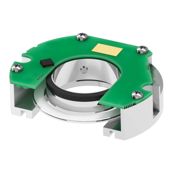
• Kit encoder with optical and magnetic scanning
• Compact and low-profile design for comfortable installation
• Up to 23 bit singleturn resolution + 1 or 65,536 revolutions
• SSI, BiSS C-mode, & RS-485 interfaces + Sine-Cosine 1Vpp track
• Direct integration into robots, motors, and OEM applications
Suitable for the following models:
AMM5Axx/xxxBG1-...
•
AMM5Axx/xxxSC1-...
•
AMM5Axx/xxxJP1-...
•
AMM5Bxx/xxxBG1-...
•
AMM5Bxx/xxxSC1-...
•
AMM5Bxx/xxxJP1-...
•
Lika Electronic
User's guide
•
Tel. +39 0445 806600
Absolute kit encoder
General contents
Preliminary information
1 - Safety summary
2 - Identification
3 - Mounting instructions
4 - Electrical connections
5 - SSI interface
6 - BiSS C-mode interface
7 – RS-485 serial interface
8 - 1Vpp Sine/Cosine output signals
9 - Diagnostic LEDs
•
info@lika.biz
11
12
20
27
31
41
49
51
•
www.lika.biz
7
8
Advertisement
Table of Contents

Related Manuals for Lika AMM5A / BG1 Series


Summary of Contents for Lika AMM5A / BG1 Series
-
Page 1: User's Guide
4 - Electrical connections AMM5Bxx/xxxSC1-... • 5 - SSI interface AMM5Bxx/xxxJP1-... • 6 - BiSS C-mode interface 7 – RS-485 serial interface 8 - 1Vpp Sine/Cosine output signals 9 - Diagnostic LEDs Lika Electronic • Tel. +39 0445 806600 • info@lika.biz • www.lika.biz... - Page 2 Tous droits réservés. This document and information contained herein are the property of Lika Electronic s.r.l. and shall not be reproduced in whole or in part without prior written approval of Lika Electronic s.r.l. Translation, reproduction and total or partial modification (photostat copies, film and microfilm included and any other means) are forbidden without written authorisation of Lika Electronic s.r.l.
-
Page 3: Table Of Contents
Table of Contents User's guide......................................1 Table of Contents....................................3 Subject Index......................................5 Typographic and iconographic conventions........................6 Preliminary information..................................7 1 - Safety summary............................8 1.1 Safety......................................8 1.2 Electrical safety..................................8 1.3 Mechanical safety..................................8 1.4 Specific handling and cleaning instructions and safety information against electrostatic discharges......................................9 2 - Identification............................ - Page 4 CRC....................................33 6.3 Control Data CD...................................34 Register address...............................34 RW....................................34 DATA.....................................34 CRC....................................34 6.4 Implemented registers..............................35 Preset....................................35 Preset setting enable............................38 Serial number................................38 Command..................................39 Save parameters..............................39 Activate Preset.................................39 Device ID..................................39 Manufacturer ID..............................39 6.5 Application notes................................40 6.6 Recommended BiSS input circuit..........................40 7 – RS-485 serial interface........................41 7.1 RS-485 port settings................................41 7.2 Frame format..................................41 7.2.1 Encoder data capture and reset..........................41...
-
Page 5: Subject Index
Subject Index Activate Preset..............39 Position.................32 Preset..................35 Preset setting enable............38 Command................39 CRC.................33, 34 Register address..............34 RW..................34 DATA..................34 Device ID................39 Save parameters...............39 Serial number..............38 Error..................32 Warning................33 Manufacturer ID...............39... -
Page 6: Typographic And Iconographic Conventions
In this guide, to make it easier to understand and read the text the following typographic and iconographic conventions are used: parameters and objects both of Lika device and interface are coloured in GREEN; • alarms are coloured in RED;... -
Page 7: Preliminary Information
Preliminary information This guide is designed to provide the most complete and exhaustive information the operator needs to correctly and safely install and operate the AMM5A & AMM5B absolute kit encoders. These encoders are available with the following interfaces: SSI interface; •... -
Page 8: Safety Summary
• failure to comply with these precautions or with specific warnings elsewhere in this manual violates safety standards of design, manufacture, and intended use of the equipment; • Lika Electronic assumes no liability for the customer's failure to comply with these requirements. 1.2 Electrical safety •... -
Page 9: Specific Handling And Cleaning Instructions And Safety Information Against Electrostatic Discharges
AMM5A & AMM5B • SSI, BiSS, & RS-485 • do not disassemble the encoder; • do not tool the encoder or the disk/ring; • delicate electronic equipment: handle with care; do not subject the device and the disk/ring to knocks or shocks; •... - Page 10 AMM5A & AMM5B • SSI, BiSS, & RS-485 CAUTION Keep magnets away from the magnetic ring in the code disk, it could be damaged by strong magnetic fields. MAN AMM5A_B SSI_BiSS_RS485 E 1.9.odt 1 - Safety summary 10 of 56...
-
Page 11: Identification
Information is listed in the delivery document too. Please always quote the order code and the serial number when reaching Lika Electronic. For any information on the technical characteristics of the product refer to the technical catalogue. -
Page 12: Mounting Instructions
AMM5A & AMM5B • SSI, BiSS, & RS-485 3 - Mounting instructions WARNING Installation must be carried out by qualified personnel only, with power supply disconnected and mechanical parts compulsorily in stop. WARNING Before handling and mounting the device please be sure to read carefully the handling instructions and safety information reported in the “1.4 Specific handling and cleaning instructions and safety information against electrostatic discharges”... - Page 13 It is important that the shaft of the code disk matches perfectly the shaft of the drive. Do not install reducing sleeves. Please always order the right size (max. Ø 24 mm). For more information please contact Lika Sales Dept. MAN AMM5A_B SSI_BiSS_RS485 E 1.9.odt...
-
Page 14: Encumbrance Sizes
AMM5A & AMM5B • SSI, BiSS, & RS-485 3.2 Encumbrance sizes (values are expressed in mm) 3.2.1 AMM5A encoder Figure 3 - Encumbrance sizes of the AMM5A encoder 3.2.2 AMM5B encoder Figure 4 - Encumbrance sizes of the AMM5B encoder MAN AMM5A_B SSI_BiSS_RS485 E 1.9.odt 3 - Mounting instructions 14 of 56... -
Page 15: Code Disk
AMM5A & AMM5B • SSI, BiSS, & RS-485 3.2.3 Code disk Figure 5 - Encumbrance sizes of the code disk MAN AMM5A_B SSI_BiSS_RS485 E 1.9.odt 3 - Mounting instructions 15 of 56... -
Page 16: Mounting The Code Disk
AMM5A & AMM5B • SSI, BiSS, & RS-485 3.3 Mounting the code disk WARNING The encoder must be adequately protected under an enclosure • appropriate for the specific application; before installation, carefully clean the code disk from dust or • fingerprints, wipe it with a soft dry cloth or camera lens tissue;... -
Page 17: Mounting The Encoder
AMM5A & AMM5B • SSI, BiSS, & RS-485 Step 2 Gently press the code disk 3 into place on the PF5019 spacing tool 1. Tighten the two M3 x 3 UNI5929 grub screws 4 to firmly fasten the code disk 3; make sure that the code disk 3 perfectly rests on the spacing tool 1 before fixing it;... - Page 18 AMM5A & AMM5B • SSI, BiSS, & RS-485 the enclosure of the encoder unit 5 does not hit or touch the code disk 3; always handle the encoder unit 5 by holding the enclosure on the sides. Step 4 Insert the M2.5 x 6 cylinder-head bolts UNI5931 7 in the holes 6, tighten both bolts 7 down to firmly fix the encoder unit 5, torque to 0.8 Nm max.
- Page 19 AMM5A & AMM5B • SSI, BiSS, & RS-485 Step 6 Connect the EC-DF19-LK-TF12-... cable to the Hirose connector of the encoder unit 5. Please make sure that the power supply is off and the battery is not wired before connecting the cable. Step 7 Connect the battery.
-
Page 20: Electrical Connections
AMM5A & AMM5B • SSI, BiSS, & RS-485 4 - Electrical connections WARNING Power supply must be turned off before performing any electrical connection! If wires of unused signals come in contact, irreparable damage could be caused to the device. Thus they must be cut at different lengths and insulated singularly. -
Page 21: Rs-485 Connection
AMM5A & AMM5B • SSI, BiSS, & RS-485 Mating connector: Hirose DF19G-14S-1C(05) female connector 4.1.2 SSI and BiSS C-mode mating cable connection (...G1-... and ...SC1-... order codes) EC-DF19-LK-TF12-... cable, it must be ordered separately Function TF12 cable Pink Data OUT - / SLO - Data OUT + / SLO + Grey Clock IN - / MA -... -
Page 22: Rs-485 Mating Cable Connection
0Vdc White_Green * Only available in multiturn encoder versions (…/65K... order code) 4.1.5 TF12 cable specifications Model : LIKA TF12 encoder cable Cross section : 6 x 2 x 28AWG Jacket : Special flame retardant PVC compound, RZ-TM2 quality Shield : Tinned copper braid, coverage >... -
Page 23: Battery Power Supply
AMM5A & AMM5B • SSI, BiSS, & RS-485 4.3 Battery power supply NOTE Battery power supply is only available in multiturn encoder versions (…/65K... order code). +Vb / 0Vb: battery supply voltage comprised between 3V and 5.5V, it is typically 3.6V. -
Page 24: Replacement Of The Battery - Error Active
AMM5A & AMM5B • SSI, BiSS, & RS-485 WARNING Now you are required to replace the battery within 1 minute! 4. install and connect the new battery; 5. switch the 5Vdc power supply off; 6. switch the 5Vdc power supply 7. -
Page 25: 1Vpp Sinusoidal Output Signals
AMM5A & AMM5B • SSI, BiSS, & RS-485 3. remove the spent battery; 4. install and connect the new battery; 5. switch the 5Vdc power supply on; the ERROR LED is on or blinks; 6. switch the 5Vdc power supply off; 7. -
Page 26: Standard Counting Direction
AMM5A & AMM5B • SSI, BiSS, & RS-485 4.6 Standard counting direction The standard counting direction provides the count up information when the shaft/code disk turns as shown in the Figure below (clockwise rotation viewed from the flange side). The counting direction is fixed and cannot be changed. Figure 6 - Standard counting direction WARNING Light alters significantly the proper operation of the system. -
Page 27: Ssi Interface
AMM5A & AMM5B • SSI, BiSS, & RS-485 5 - SSI interface Order code: AMM5Axx/xxxBG1-... AMM5Bxx/xxxBG1-... 5.1 SSI (Synchronous Serial Interface) Synchronous Serial (the acronym Interface) is a synchronous point-to-point serial interface engineered unidirectional data transmission between one Master and one Slave. Developed in the first eighties, it is based on the RS- 422 serial standard. -
Page 28: Msb Left Aligned" Protocol
AMM5A & AMM5B • SSI, BiSS, & RS-485 At each change of the clock signal and at each subsequent rising edge (2) one bit is clocked out at a time, up to LSB, so completing the data word transmission. The cycle ends at the last rising edge of the clock signal (3). This means that up to n + 1 rising edges of the clock signals are required for each data word transmission (where n is the bit resolution);... -
Page 29: Recommended Transmission Rates
AMM5A & AMM5B • SSI, BiSS, & RS-485 Structure of the position information AMM5A17/1BG1... … AMM5B17/1BG1... AMM5A21/1BG1... … AMM5B21/1BG1... AMM5A23/1BG1... … AMM5B23/1BG1... AMM5A17/65KBG1... … AMM5B17/65KBG1... AMM5A21/65KBG1... … AMM5B21/65KBG1... AMM5A23/65KBG1... … AMM5B23/65KBG1... value … 5.3 Recommended transmission rates The SSI interface has a frequency of data transmission ranging between 100 kHz and 4 MHz. -
Page 30: Recommended Ssi Input Circuit
AMM5A & AMM5B • SSI, BiSS, & RS-485 5.4 Recommended SSI input circuit MAN AMM5A_B SSI_BiSS_RS485 E 1.9.odt 5 - SSI interface 30 of 56... -
Page 31: Biss C-Mode Interface
6 - BiSS C-mode interface Order code: AMM5Axx/xxxSC1-... AMM5Bxx/xxxSC1-... Lika encoders are always Slave devices and comply with the “BiSS C-mode interface” and the “Standard encoder profile”. Refer to the official BiSS website for all information not listed in this manual (www.biss-interface.com). -
Page 32: Single Cycle Data Scd
AMM5A & AMM5B • SSI, BiSS, & RS-485 6.2 Single Cycle Data SCD 6.2.1 SCD structure SCD data has a variable length according to the resolution of the encoder. It is nbitres+7 long where “nbitres” is the resolution of the encoder expressed in bits. It consists of the following elements: position value (Position), 1 error bit nE (Error), 1 warning bit nW (Warning) and a 6-bit CRC Cyclic Redundancy Check (CRC). -
Page 33: Warning
AMM5A & AMM5B • SSI, BiSS, & RS-485 o the gap between the circuitry and the disk is out of tolerance o the circuitry is not installed properly 2. The battery is spent. The encoder cannot operate. You are required to replace the battery. -
Page 34: Control Data Cd
AMM5A & AMM5B • SSI, BiSS, & RS-485 6.3 Control Data CD Main control data is described in this section. Please refer to the official BiSS documents for complete CD structure: “BiSS C Protocol Description” in the BiSS homepage. Register address It sets the number of the register you need either to read or to write. -
Page 35: Implemented Registers
AMM5A & AMM5B • SSI, BiSS, & RS-485 6.4 Implemented registers Register (hex) Function 11 … 17 Preset Preset setting enable Serial number 44 … 47 Command Device ID 78 … 7D 7E - 7F Manufacturer ID All registers described in this section are listed as follows: Function name [Address, Attribute] Description of the function and specification of the default value. - Page 36 AMM5A & AMM5B • SSI, BiSS, & RS-485 The Preset value must be less than the “Total Hardware resolution”. NOTE We suggest setting the preset when the encoder shaft is in stop. NOTE Preset Please note that the bit structure of the registers is as follows: Byte 11 Byte 12...
- Page 37 AMM5A & AMM5B • SSI, BiSS, & RS-485 Preset To properly set the value see the following example. PRESET SETTING EXAMPLE In the 21-bit singleturn resolution encoder (2 = 2,097,152 information), you Preset want to set the following value = 1,000,003 = 0F4243h = 1111 0100 0010 0100 0011 Preset...
-
Page 38: Preset Setting Enable
AMM5A & AMM5B • SSI, BiSS, & RS-485 6. To activate the new Preset value, you must use the Activate Preset Command Command function in the register (set “02” in the register). Function ADDR DATA Tx Preset setting enable Writing in the Preset registers Preset setting enable... -
Page 39: Command
… 2 ASCII Manufacturer ID [7E – 7F, ro] These registers contain the Manufacturer ID. Identification name is expressed hexadecimal ASCII code. Register ASCII Li = Lika Electronic MAN AMM5A_B SSI_BiSS_RS485 E 1.9.odt 6 - BiSS C-mode interface 39 of 56... -
Page 40: Application Notes
AMM5A & AMM5B • SSI, BiSS, & RS-485 6.5 Application notes Data transmission: Parameter Value Clock Frequency Min 50 kHz, max 10 MHz BiSS time-out Self-adaptable to the clock Time-out is self-adaptable to the clock frequency. It is 1.5 * 1 / clock frequency. If clock frequency = 50 kHz, then the time-out is 30 µs. -
Page 41: Rs-485 Serial Interface
AMM5A & AMM5B • SSI, BiSS, & RS-485 7 – RS-485 serial interface Order code: AMM5Axx/xxxJP1-... AMM5Bxx/xxxJP1-... 7.1 RS-485 port settings Serial port settings are as follows: Serial port settings Value Baud rate (Mbit/s) Byte size Parity None Stop bits Flow control None 7.2 Frame format... -
Page 42: Read Register
AMM5A & AMM5B • SSI, BiSS, & RS-485 7.2.3 Read register → Master Encoder → Encoder Master 7.3 Field detail 7.3.1 Control Field Control Field CF is related to Data Field DF, for a correct Data ID see the “7.4 Data Field”... -
Page 43: Data Field
AMM5A & AMM5B • SSI, BiSS, & RS-485 7.4 Data Field Data Field DF is related to Control Field CF, for a correct Data ID see the “7.3.1 Control Field” section on page 42. Data Data ID ABS0 ABS1 ABS2 Data ID ABM0 ABM1... -
Page 44: Encoder Errors
AMM5A & AMM5B • SSI, BiSS, & RS-485 7.4.1 Encoder errors See the ALMC byte in the previous “7.4 Data Field” section. How to Flag Explanation clear Function: There is a delay which is needed for the Auto clear encoder to successfully process data at power-on. Or (turning the encoder is accomplishing a reset command. -
Page 45: Resetting An Error
AMM5A & AMM5B • SSI, BiSS, & RS-485 7.4.2 Resetting an error Function Data ID Description Singleturn and multiturn Data ID 8 Data ID must be transmitted to the data resetting encoder 10 times in succession at transmission intervals of 40 µs or more while the shaft is in stop. -
Page 46: Address Field And Eeprom Data Field
AMM5A & AMM5B • SSI, BiSS, & RS-485 Singleturn encoder position: DF0: LS byte DF2: MS byte position = (DF2 << 16) + (DF1 << 8) + DF0; with 23 bit resolution: 23 Bit 22 ... singleturn encoder position with 21 bit resolution: 21 Bit 20 ... -
Page 47: Crc Field
AMM5A & AMM5B • SSI, BiSS, & RS-485 ADF of Writing is being executed request Request for writing is invalid MEM BUSY When status of transmission data from the encoder is logical value “1” = Writing is being executed, the writing process based upon the request is not executed. - Page 48 AMM5A & AMM5B • SSI, BiSS, & RS-485 for (i=0; i<8; ++i) CRC[i] = 0;// Init before calculation for (i=0; i<strlen(BitString); ++i) DoInvert = ('1'==BitString[i]) ^ CRC[7];// XOR required? CRC[7] = CRC[6]; CRC[6] = CRC[5]; CRC[5] = CRC[4]; CRC[4] = CRC[3]; CRC[3] = CRC[2];...
-
Page 49: 1Vpp Sine/Cosine Output Signals
AMM5A & AMM5B • SSI, BiSS, & RS-485 8 - 1Vpp Sine/Cosine output signals NOTE Sine/Cosine output signals are only available in SSI (...BG1... order code) and BiSS (...SC1... order code) models. A (COSINE) and B (SINE) signals are to be intended with CW rotation as viewed from the shaft side. - Page 50 AMM5A & AMM5B • SSI, BiSS, & RS-485 = 2.5V ± 0.5V = 1Vpp * Av Av = R2 / R1 MAN AMM5A_B SSI_BiSS_RS485 E 1.9.odt 8 - 1Vpp Sine/Cosine output signals 50 of 56...
-
Page 51: Diagnostic Leds
AMM5A & AMM5B • SSI, BiSS, & RS-485 9 - Diagnostic LEDs The encoder is equipped with two LEDs, they are meant to visually show a fault condition during operation. When you install the encoder, as soon as the power supply is switched on (see Step 8), the LEDs blink for a while and then go off, if the installation procedure is successful. -
Page 52: Default Parameters List
AMM5A & AMM5B • SSI, BiSS, & RS-485 10 - Default parameters list BiSS C-mode interface Parameters list Default value * Preset 00 00 00 00 00 Preset setting enable * All values are expressed in hexadecimal notation. MAN AMM5A_B SSI_BiSS_RS485 E 1.9.odt 10 - Default parameters list 52 of 56... - Page 53 This page intentionally left blank...
- Page 54 This page intentionally left blank...
- Page 55 This page intentionally left blank...
- Page 56 BiSS registers 44 … 47 and 78 … 7D updated AMM5B model introduced (mounting information 21.04.2021 updated, characteristics of the mounting flange; encumbrance sizes updated) 09.12.2021 Encumbrance size drawings updated Lika Electronic Via S. Lorenzo, 25 • 36010 Carrè (VI) • Italy Tel. +39 0445 806600 Fax +39 0445 806699 info@lika.biz...
Need help?
Do you have a question about the AMM5A / BG1 Series and is the answer not in the manual?
Questions and answers