Lika AS58 PB User Manual

Lika AS58 PB User Manual

Profibus-dp profile for encoders, up to 13-bit singleturn encoder 8,192 cpr, up to 25-bit multiturn encoder 8,192 cpr x 4,096 rev., connection caps, profibus dp configurable as class 1 and class 2 slave
Hide thumbs Also See for AS58 PB:

Advertisement

Quick Links

Smart encoders & actuators
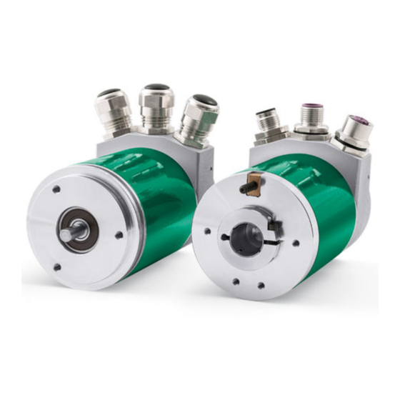
AS58 PB
AM58 PB
ASC58 PB
AMC58 PB
CC-PB, CC-PB-C
• AS58 up to 13-bit singleturn encoder (8,192 cpr)
• AM58 up to 25-bit multiturn encoder (8,192 cpr x 4,096 rev.)
• CC-PB and CC-PB-C connection caps
• Profibus DP configurable as Class 1 and Class 2 Slave
Suitable for the following models:
AS58 PB, AS58S PB
ASC58 PB, ASC59 PB, ASC60 PB
AM58 PB, AM58S PB
AMC58 PB, AMC59 PB, AMC60 PB
CC-PB
CC-PB-C
Lika Electronic

User's guide

Tel. +39 0445 806600
Profibus-DP profile for encoders
General Contents
1 - Safety summary
2 - Identification
3 - Mounting instructions
4 - Electrical connections
5 - Quick reference
6 - Profibus interface
7 – Default parameters list
info@lika.biz
17
19
20
25
32
50
66
www.lika.biz

Advertisement

Table of Contents
loading
Need help?

Need help?

Do you have a question about the AS58 PB and is the answer not in the manual?

Questions and answers

Summary of Contents for Lika AS58 PB

  • Page 1: User's Guide

    • CC-PB and CC-PB-C connection caps • Profibus DP configurable as Class 1 and Class 2 Slave Suitable for the following models: General Contents AS58 PB, AS58S PB • 1 - Safety summary ASC58 PB, ASC59 PB, ASC60 PB •...
  • Page 2 Tous droits réservés. This document and information contained herein are the property of Lika Electronic s.r.l. and shall not be reproduced in whole or in part without prior written approval of Lika Electronic s.r.l. Translation, reproduction and total or partial modification (photostat copies, film and microfilm included and any other means) are forbidden without written authorisation of Lika Electronic s.r.l.
  • Page 3: Table Of Contents

    Table of contents User's guide......................................1 Table of contents....................................3 Subject index.....................................5 Typographic and iconographic conventions........................6 Preliminary information................................7 Glossary of Profibus terms................................8 1 - Safety summary..................................17 1.1 Safety......................................17 1.2 Electrical safety..................................17 1.3 Mechanical safety................................18 2 - Identification..................................19 3 - Mounting instructions..............................20 3.1 Solid shaft encoders................................20 3.1.1 Customary installation..............................20 3.1.2 Installation using fixing clamps (code LKM-386)..................21 3.1.3 Installation using a mounting bell (code PF4256)..................21...
  • Page 4 6.4.2 Bytes 11 and 12................................55 Counts per revolution..............................55 6.4.3 Bytes 13 … 16................................57 Total resolution................................57 6.5 DDLM_Chk_Cfg..................................60 6.6 DDLM_Data_Exchange..............................61 Position....................................61 Preset.....................................61 6.7 DDLM_Slave_Diag................................63 6.8 "Red zone"....................................64 7 – Default parameters list..............................66...
  • Page 5: Subject Index

    Subject index Preset..................61 Class 2 functionality............54 Code sequence..............54 Scaling function...............54 Counts per revolution............55 Total resolution..............57 Position.................61...
  • Page 6: Typographic And Iconographic Conventions

    Typographic and iconographic conventions In this guide, to make it easier to understand and read the text the following typographic and iconographic conventions are used: parameters and objects both of the device and the interface are coloured in GREEN; • alarms are coloured in RED;...
  • Page 7: Preliminary Information

    Preliminary information This guide is designed to provide the most complete information the operator needs to correctly and safely install and operate the following encoders fitted with Profibus interface: ASxxx12/PB-xx (12 bit singleturn encoder) ASxxx13/PB-xx (13 bit singleturn encoder) AMxxx12/4096PB-xx (12 + 12 bit multiturn encoder) AMxxx13/4096PB-xx (13 + 12 bit multiturn encoder)
  • Page 8: Glossary Of Profibus Terms

    Glossary of Profibus terms Profibus, like many other networking systems, has a set of unique terminology. Table below contains a few of the technical terms used in this guide to describe the Profibus interface. They are listed in alphabetical order. Address (Station) IEC 61158-2: Medium attachment unit identification - unique number of a station connected to a segment (participant).
  • Page 9 Class See “DP Master”, “DP Master Class 1 (DPM1)” and “DP Master Class 2 (DPM2)”. Class 1 encoder Encoder class must be set when you configure the device. Mandatory Class 1 provides the basic functions of the device and can be used for: sending the position value (see Position parameter);...
  • Page 10 binary divisor and compares the calculated remainder to a value stored in the frame by the sending node. Data Rate (Baud rate) Other common terms are "data transfer rate" and "transmission rate". Within PROFIBUS DP this is the amount of data transferred across a fieldbus segment per second.
  • Page 11 DP Master IEC 61158-5: Within PROFIBUS DP a fieldbus node that can be either Master Class 1 or Master Class 2. A Master Class 1 is a controlling device which controls several DP Slaves (field devices). NOTE: This is usually hosted by a programmable controller or a process controller.
  • Page 12 configuration phase. Distinction is made between a device GSD (for an individual device only) and a profile GSD, which may be used for devices that comply exactly with a profile such as a "PA device". GSDs for different languages may be provided in separate files with corresponding file extensions (*.gse for English, *.gsg for German, etc.) or altogether in one file (*.gsd).
  • Page 13 (PROFIBUS Schweiz in Switzerland). In the following years, additional Regional PROFIBUS & PROFINET Associations (RPAs) were added. In 1995, all the RPAs joined together under the international umbrella association PROFIBUS & PROFINET International (PI). Today, PROFIBUS is represented by 25 RPAs around the world (including PNO) with over 1400 members, including most if not all major automation vendors and service suppliers, along with many end users.
  • Page 14 clock synchronization; • redundancy. • PROFIBUS DP is standardized within IEC 61158 and IEC 61784, communication profile families 3/1 and 3/2. The term "PROFIBUS DP" is also a synonym for the RS-485 based deployments within factory automation. PROFIdrive Communication technology especially adopted to the requirements of position and speed controlled drive applications (e.g.
  • Page 15 Physical layer protocol data unit (PhPDU); • Data link protocol data unit (DLPDU); • Application protocol data unit (APDU). • Slave Parametrization For a DP Slave several levels of parametrization exist. (1) The parameters on the DP communication level can be defined via a GSD file and comprise features such as baud rates, timing constraints, identification, options, transferable data structures, publisher subscriber links, etc.
  • Page 16 rate) switching speed, or number of transitions (voltage or frequency changes) that are made per second. Within PROFIBUS DP the possible transmission rates depend on the MAU (Medium Attachment Unit) in use. Watchdog Control IEC 61158-6: This timer is part of the DP layer within a Slave. It is restarted by received requests from the bus Master and will set the outputs of a Slave to a fail-safe state after the expiration of the timer.
  • Page 17: Safety Summary

    • elsewhere in this manual violates safety standards of design, manufacture, and intended use of the equipment; Lika Electronic assumes no liability for the customer's failure to comply • with these requirements. 1.2 Electrical safety Turn off the power supply before connecting the device;...
  • Page 18: Mechanical Safety

    Ax58x Profibus-DP ground point provided in the cap, use one TCEI M3 x 6 cylindrical head screw with two tooth lock washers. 1.3 Mechanical safety Install the device following strictly the information in the “3 - Mounting • instructions” section on page 20; mechanical installation has to be carried out with stationary mechanical •...
  • Page 19: Identification

    Information is listed in the delivery document too. Please always quote the order code and the serial number when reaching Lika Electronic for purchasing spare parts or needing assistance. For any information on the technical characteristics of the product refer to the technical catalogue.
  • Page 20: Mounting Instructions

    Ax58x Profibus-DP 3 - Mounting instructions WARNING Installation and maintenance operations must be carried out by qualified personnel only, with power supply disconnected and mechanical parts absolutely in stop. For any information on the mechanical data and the electrical characteristics of the encoder please refer to the technical catalogue.
  • Page 21: Installation Using Fixing Clamps (Code Lkm-386)

    Ax58x Profibus-DP 3.1.2 Installation using fixing clamps (code LKM-386) a [mm] b [mm] c [mm] d [mm] AS58, AM58 50 F7 AS58S, AM58S 36 H7 3.1.3 Installation using a mounting bell (code PF4256) NOTE In order to guarantee reliability over time of the encoder mechanical parts, we recommend a flexible coupling to be installed between the encoder and the motor shaft.
  • Page 22: Hollow Shaft Encoders

    • insert the anti-rotation pin 1 into the slot on the flange of the encoder; this secures it in place by grub screw 2, preset at Lika; • fix the collar 3 to the encoder shaft (apply threadlocker to screw 3).
  • Page 23: Asc59, Amc59 With Fixing Plate

    Ax58x Profibus-DP 3.2.2 ASC59, AMC59 with fixing plate • Mount the encoder on the motor shaft using the reducing sleeve 8 (if supplied). Avoid forcing the encoder shaft; • fasten the fixing plate 4 to the rear of the motor using two M3 cylindrical head screws 5;...
  • Page 24: Asc60, Amc60 With Antirotation Pin And Fixing Plate

    Ax58x Profibus-DP 3.2.3 ASC60, AMC60 with antirotation pin and fixing plate • Fix the tempered pin 6 to the rear of the motor; • mount the encoder on the motor shaft using the reducing sleeve 8 (if supplied). Avoid forcing the encoder shaft; •...
  • Page 25: Electrical Connections

    Ax58x Profibus-DP 4 - Electrical connections WARNING Electrical connection has to be carried out by qualified personnel only, with power supply disconnected and mechanical parts compulsorily in stop. 4.1 Connection cap WARNING Do not remove or mount the connection cap with power supply switched ON. Damage may be caused to internal components.
  • Page 26: Cc-Pb Connection Cap With Pgs (Figure 1)

    Ax58x Profibus-DP 4.2 CC-PB connection cap with PGs (Figure 1) Figure 1 Cable output versions (CC-PB connection cap) are equipped with three PG9 cable glands for BUS IN and BUS OUT connections as well as for power supply connection. The bus cables can be connected directly to the terminal connectors located by each cable gland.
  • Page 27: Cc-Pb-C Connection Cap With M12 Connectors (Figure 2)

    Ax58x Profibus-DP 4.3 CC-PB-C connection cap with M12 connectors (Figure 2) Figure 2 Connector output versions (CC-PB-C connection cap) are equipped with three M12 connectors with pin-out in compliance with the Profibus standard. Therefore you can use standard Profibus cables commercially available. Power supply M12 connector A coding...
  • Page 28: Ground Connection

    Ax58x Profibus-DP 4.4 Ground connection Minimize noise by connecting the shield and/or the connector housing and/or the frame to ground. Make sure that ground is not affected by noise. The connection point to ground can be situated both on the device side and on user’s side.
  • Page 29: Node Address: Dip A (Figure 1 And Figure 2)

    Ax58x Profibus-DP 4.6 Node address: DIP A (Figure 1 and Figure 2) WARNING Power supply must be turned off before performing this operation! The node address must be set via hardware using the DIP A dip- switches located inside connection cap. Allowed addresses are from 0 to 125.
  • Page 30: Baud Rate

    Ax58x Profibus-DP 4.7 Baud rate The baud rate is set by the Master via software during the configuration of the node (Slave). This device supports the following baud rates (they are listed in the .GSD file too): 9.6 kbit/s, 19.2 kbit/s, 93.75 kbit/s, 187.5 kbit/s, 500 kbit/s, 1.5 Mbit/s, 3 Mbit/s, 6 Mbit/s, 12 Mbit/s.
  • Page 31: Diagnostic Leds

    Ax58x Profibus-DP 4.9 Diagnostic LEDs Two LEDs located in the rear side of the connection cap are designed to show the operating or fault status of the Profibus-DP interface. Fault (red) Power (green) Event Power supply is turned off or hardware breakdown not recognized Correct operation (communication is on, the device is sending / receiving messages)
  • Page 32: Quick Reference

    WARNING For ASx58x singleturn encoders (order code: AS58xx/PB-xx): the default value preset by Lika in the Counts per revolution item of the AS58_Vx.GSx GSD file is 4096 (12 bits); for this reason, if you have a 13-bit singleturn encoder (order code: AS5813/PB-xx) and you want to use the overall resolution, you must set the Counts per revolution item to 8192 (13 bits).
  • Page 33 Ax58x Profibus-DP In the menu bar of the HW Config window of STEP7, select Install GSD File… command from the Options menu. In the window that appears you can select the GSD file specific to the unit you need to install in your Siemens control system. Choose among the available files the one you need: GSD file for AS58 singleturn encoder or GSD file for AM58 multiturn encoder, in either Italian or English language.
  • Page 34: Adding A Node To The Project

    “BUS”. For instance, drag the LIKA AM58 module. Then drag the Lika AM58 Class 1 or the Lika AM58 Class 2 submodule to the variables table at the bottom of the main window; for instance, install the Lika Lika AM58 Class 2 submodule.
  • Page 35: Encoder Configuration Parameters

    Config main window and select the LIKA AM58 item you have just installed (Lika AM58 Class 2 in the example), it is available in the variables table at the bottom of the main window; then right-click the item and press the Object Properties...
  • Page 36 Ax58x Profibus-DP Class 2 example In the Parameter Assignment page, some items (Code sequence, Class 2 functionality, Scaling function) are to be set by scrolling through the available options in the drop-down box. While the parameters concerning the resolution must be entered in decimal notation. Please note that the Total resolution value has to be split into two separate fields, namely Total resolution (high) and Total resolution (low).
  • Page 37 Ax58x Profibus-DP EXAMPLE 1 Let's suppose we need to program the following encoder: “AS5812/PB-xx” 12-bit singleturn encoder.  Hardware counts per revolution = 12 bits/rev. (4096 cpr)  Hardware number of revolutions = 1 rev.  Hardware total resolution = 12 bits (4096  1 = 4096) We want to set: 4096 counts per revolution.
  • Page 38 Ax58x Profibus-DP EXAMPLE 2 Let's suppose we need to program the following encoder: “AS5813/PB-xx” 13-bit singleturn encoder.  Hardware counts per revolution = 13 bits/rev. (8192 cpr)  Hardware number of revolutions = 1 rev.  Hardware total resolution = 13 bits (8192  1 = 8192) We want to set: 8192 counts per revolution.
  • Page 39 Ax58x Profibus-DP EXAMPLE 3 Let's suppose we need to program the following encoder: “AM5812/4096PB-xx” 24-bit multiturn encoder.  Hardware counts per revolution = 12 bits/rev. (4096 cpr)  Hardware number of revolutions = 12 bits (4096 rev.)  Hardware total resolution = 24 bits (4096 ...
  • Page 40 Ax58x Profibus-DP EXAMPLE 4 Let's suppose we need to program the following encoder: “AM5813/4096PB-xx” 25-bit multiturn encoder.  Hardware counts per revolution = 13 bits/rev. (8192 cpr)  Hardware number of revolutions = 12 bits (4096 rev.)  Hardware total resolution = 25 bits (8192 ...
  • Page 41 Ax58x Profibus-DP resulting number of revolution complies with the Hardware number of revolutions of the device. Let's say our encoder is programmed as in EXAMPLE 4: Counts per revolution: 8192 Total resolution= 33,554,432 = 8192 (cpr) * 4096 (rev.), so: Total resolution (high) = 512;...
  • Page 42 Ax58x Profibus-DP EXAMPLE 5 Let's suppose we need to program the following encoder: “AS5813/PB-xx” 13-bit singleturn encoder.  Hardware counts per revolution = 13 bits/rev. (8192 cpr)  Hardware number of revolutions = 1 rev.  Hardware total resolution = 13 bits (8192  1 = 8192) We want to set: 100 counts per revolution.
  • Page 43 Ax58x Profibus-DP EXAMPLE 6 Let's suppose we need to program the following encoder: “AM5813/4096PB-xx” 25-bit multiturn encoder.  Hardware counts per revolution = 13 bits/rev. (8192 cpr)  Hardware number of revolutions = 12 bits (4096 rev.)  Hardware total resolution = 25 bits (8192 ...
  • Page 44 Ax58x Profibus-DP WARNING We recommend the Number of revolutions to be set to a value that is a power of 2. If the set number of revolutions is not a power of 2, the so-called “Red Zone” will be created and the encoder will necessarily work inside its limits. For any information on the "Red Zone"...
  • Page 45 Ax58x Profibus-DP EXAMPLE 8 Let's suppose we need to program the following encoder: “AM5813/4096PB-xx” 25-bit multiturn encoder.  Hardware counts per revolution = 13 bits/rev. (8192 cpr)  Hardware number of revolutions = 12 bits (4096 rev.)  Hardware total resolution = 25 bits (8192 ...
  • Page 46: Reading The Diagnostic Information

    (i.e. to enter the online status). To do this, select Station\Open online in the HW Config window or press the Online<->Offline button (see the icon on the left). When the unit is online, select the LIKA AM58 module first and then the PLC\Module Information... command to enter the Module Information window.
  • Page 47 Ax58x Profibus-DP 6-byte diagnostics Byte Description Status 1 Status 2 Status 3 Master ID Manufacturer ID MAN Ax58 PB_Ax58S PB_AxC58 PB E 2.6.odt 5 - Quick reference...
  • Page 48: Setting The Preset Value

    Ax58x Profibus-DP 5.3 Setting the Preset value EXAMPLE Position The encoder having device address 1 transmits the value to the Master. It is loaded into variables ED 100 … ED103 (4 bytes). Preset value is sent to the encoder by using the variables AD 100 … AD103 (4 bytes).
  • Page 49 Ax58x Profibus-DP happen, we recommend "MD" reference operators (pointers) to be used for encoder position and Preset value. MAN Ax58 PB_Ax58S PB_AxC58 PB E 2.6.odt 5 - Quick reference...
  • Page 50: Profibus Interface

    WARNING For ASx58x singleturn encoders (order code: AS58xx/PB-xx): the default value preset by Lika in the Counts per revolution item of the AS58_Vx.GSx GSD file is 4096 (12 bits); for this reason, if you have a 13-bit singleturn encoder (order code: AS5813/PB-xx) and you want to use the overall resolution, you must set the Counts per revolution item to 8192 (13 bits).
  • Page 51: Classes Of The Device Profile

    Ax58x Profibus-DP 6.2 Classes of the Device profile Class The encoder class must be set when you configure the device. See also the 2 functionality operating parameter on page 54. Class 1 allows basic functions of the device and can be used: Position ...
  • Page 52 Ax58x Profibus-DP Types of communication messages Transmission of data between the Master and the Slave is carried out using the following types of messages:  DDLM_Set_Prm: It is used to configure the Slave. This communication mode is active immediately after the power is turned ON and is used to send parameters from the Master to the Slave (see the “6.4 DDLM_Set_Prm”...
  • Page 53: Ddlm_Set_Prm

    Ax58x Profibus-DP 6.4 DDLM_Set_Prm When the system is turned On, the controller sends configuration data set by the operator to the absolute encoder (DDLM_Set_Prm mode). Parameters transmission depends on the configuration chosen by the operator. Customarily data is sent automatically while data setting is carried out through a user's interface available in the controller's software (for instance, STEP7, see the “5.1 Configuring the encoder via Siemens STEP7“...
  • Page 54: Code Sequence

    Ax58x Profibus-DP Code sequence Code sequence parameter sets whether the position value output by the transducer increases (count up information) when the encoder shaft rotates clockwise (CW) or when the encoder shaft rotates counter-clockwise (CCW). Code sequence When = CW (0) the position information increases when the Code sequence encoder shaft rotates clockwise;...
  • Page 55: Counts Per Revolution

    Ax58x Profibus-DP of inconsistent values, the system does not go online and visually warns about the wrong parametrization and fault condition by means of the diagnostic LEDs. WARNING Every time you enable the scaling function and/or change the scaled values (see Counts per revolution Total resolution parameters), then you are...
  • Page 56 Ax58x Profibus-DP The custom singleturn resolution must be less than or equal to the physical singleturn resolution (value of the hardware counts per revolution). You are allowed to set any integer value less than or equal to the Hardware counts per revolution. However we suggest setting a value that is a power of 2 (1, 2, 4, …...
  • Page 57: Total Resolution

    Ax58x Profibus-DP WARNING Every time you change the value in this parameter, then you are required to set Preset and activate a new preset (see the parameter). 6.4.3 Bytes 13 … 16 Total resolution WARNING This is only available when the encoder Class 2 is installed. Total resolution Class 2 You can activate a new value next to this...
  • Page 58 Ax58x Profibus-DP WARNING If you set a value greater than the maximum allowed value (i.e. greater than the value of the Hardware total resolution), the encoder falls into an error signalling the faulty condition through the diagnostic LEDs (see on page 31). WARNING When you set a new value next to the Total resolution...
  • Page 59 Ax58x Profibus-DP EXAMPLE “AS5812/PB-xx”: single-turn encoder with 12-bit resolution  Hardware counts per revolution = 12 bit/turn (4096 cpr)  Hardware number of revolutions = 1 rev.  Hardware total resolution = 12 bit (4096  1 = 4096) “AS5813/PB-xx”: single-turn encoder with 13-bit resolution ...
  • Page 60 Ax58x Profibus-DP WARNING Total resolution Please note that the in Step 7 the value has to be split into two separate fields, namely Total resolution (high) and Total resolution (low). This value in fact must be entered in two words. Please refer to the examples on page 37 to understand how the Total resolution value has to be divided into two parts: a high part and a low part.
  • Page 61: Preset

    Ax58x Profibus-DP 6.6 DDLM_Data_Exchange This is the normal operational status of the system. The Slave (no matter if set to Position Class 1 or Class 2) can both transmit the value to the Master and Preset receive the value from the Master. Position (Encoder ...
  • Page 62 Ax58x Profibus-DP EXAMPLE Preset value to be set = 0000 0500hex Position Current encoder = 0000 2267hex Byte Cycle 31-24 23-16 15-8 80hex 00hex 05hex 00hex MS 10000000 00000000 00000101 00000000 1° 00hex 00hex 22hex 67hex SM 00000000 00000000 00100010 01100111 MS 2°...
  • Page 63 6.7 DDLM_Slave_Diag The Master device can send a request for diagnostic information at any time to the Slave device. Lika encoders implement the standard diagnostic information (6 bytes). For any information on the DP Slave diagnostics please refer to the “Profibus Specification”...
  • Page 64 Ax58x Profibus-DP 6.8 "Red zone" The so-called "red zone" occurs when: Total resolution Number of revolutions = Counts per revolution is NOT a power of 2. When this problem arises, the device must operate within the “red zone” for a certain number of positions.
  • Page 65 Ax58x Profibus-DP It follows that the encoder will work within the limits of the "read zone" for 96 revolutions (4096 - 2 * 2000 = 96), i.e. for 480,000 counts (96 * 5000). The problem can be explained graphically: NOTE ...
  • Page 66 Ax58x Profibus-DP 7 – Default parameters list Default values preset in the GSD file for AS58 singleturn encoder (AS58_Vx.GSx) Parameters list Default value Code sequence Class 2 functionality Scaling function Counts per 4096 revolution Total resolution 4096 Default values preset in the GSD file for AM58 multiturn encoder (AM58_Vx.GSx) Parameters list Default value...
  • Page 67 This page intentionally left blank...
  • Page 68 Ce dispositif doit être alimenté par un circuit de Classe 2 ou à très basse tension ou bien en appliquant une tension maxi de 30Vcc. Voir le code de commande pour la tension d'alimentation. Lika Electronic Via S. Lorenzo, 25 • 36010 Carrè (VI) •...

Table of Contents