
Subscribe to Our Youtube Channel
Related Manuals for Luxul XMS-1208P


Summary of Contents for Luxul XMS-1208P
- Page 1 QUICK INSTALL GUIDE 12-Port/8 PoE+ Gigabit Managed Switch XMS-1208P Includes: XMS-1208P 12-Port/8 PoE+ Switch „ Rack Mount Kit „ Rubber Feet „ Power Cord „...
- Page 2 INSTALLATION AND SETUP Physical Installation The XMS-1208P can easily be installed in a standard 19” rack. Two mounting ears are included for installing and stabilizing the switch. When attaching the mounting ears and installing the switch in a rack, please refer to the following illustration:...
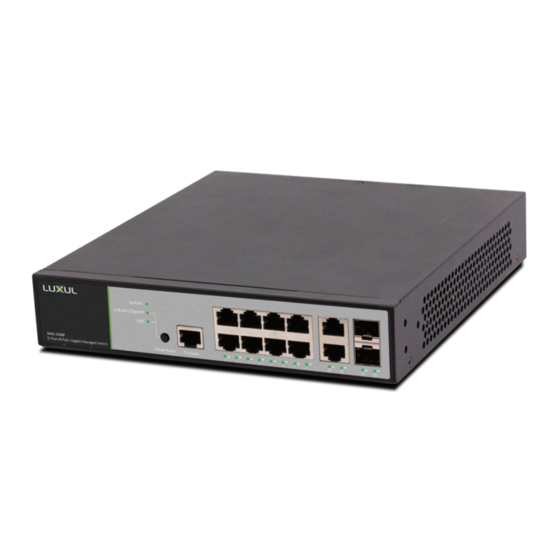
- Page 3 Ports 9 and 10 are Gigabit Ethernet only (non PoE), while ports 11 and 12 are Gigabit SFP ports. Use the included power cable to connect the XMS-1208P to a surge- protected outlet. The AC input socket is on the rear panel. The built-in power supply supports 100~240VAC at 50-60Hz.
- Page 4 Preparing for Access IP Addressing If the XMS-1208P is connected to a network with a 192.168.0.X address scheme, and your computer shares a similar address on the same network, you can skip to the next step, Access and Setup .
- Page 5 Hardware Operation Front Panel The front panel of the XMS-1208P includes 1 console port, 10 Gigabit RJ-45 ports, and 2 Gigabit SFP ports as well as LED status indicators for each port. A mode/ reset button switches the display between Link/Activity and PoE modes.
- Page 6 Mode/Reset Button to Change LED Functionality Tapping the Mode/Reset button briefly switches the port indicators between displaying port link speed and PoE status. The following chart shows the LED indicators of the XMS-1208P along with an explanation of the indicator’s properties: Indicator...
- Page 7 Link/Act and PoE LEDs turn off, then release the Reset button and the switch automatically restores factory default settings and reboots. Once the System LED starts flashing again, the XMS-1208P is running with factory defaults. CAUTION: Please note that restoring Default Settings will remove...
- Page 8 Luxul product. © Copyright 2018 Luxul. All rights reserved. The name Luxul, the Luxul logo, the Luxul logo mark and Simply Connected are all trademarks and or registered trademarks of Luxul Wireless, Inc. All other trademarks and registered trademarks are property of their respective holders.
Need help?
Do you have a question about the XMS-1208P and is the answer not in the manual?
Questions and answers