Table of Contents
Advertisement
Quick Links
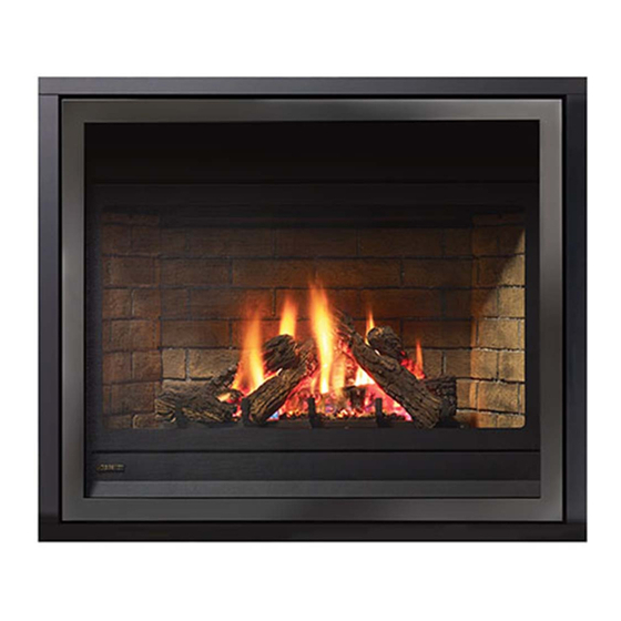
Regency Bellavista
WARNING:
If the information in these instructions are not followed exactly,
a fi re or explosion may result causing property damage,
personal injury or loss of life.
FOR YOUR SAFETY
Do not store or use gasoline or other fl ammable vapors and
liquids in the vicinity of this or any other appliance.
Installation and service must be performed by a qualifi ed
installer, service agency or the gas supplier.
Tested by:
FPI FIREPLACE PRODUCTS INTERNATIONAL LTD. 6988 Venture St., Delta, BC Canada, V4G 1H4
918-872
Gas Fireplace
Installer: Please complete the details on the back cover
and leave this manual with the homeowner.
Homeowner: Please keep these instructions for future reference.
B41XTE
™
FOR YOUR SAFETY
What to do if you smell gas:
Do not try to light any appliance
Do not touch any electrical switch:
do not use any phone in your
building.
Immediately call your gas supplier
from a neighbour's phone. Follow
the gas supplier's instructions.
If you cannot reach your gas
supplier, call the fi re department.
Owners &
Installation Manual
MODELS: B41XTE-NG
B41XTE-LP
www.regency-fi re.com
03/04/10
Advertisement
Table of Contents

Subscribe to Our Youtube Channel
Related Manuals for Regency Fireplace Products Bellavista B41XTE


Summary of Contents for Regency Fireplace Products Bellavista B41XTE
- Page 1 Owners & B41XTE Regency Bellavista ™ Installation Manual Gas Fireplace MODELS: B41XTE-NG B41XTE-LP www.regency-fi re.com WARNING: FOR YOUR SAFETY If the information in these instructions are not followed exactly, What to do if you smell gas: a fi re or explosion may result causing property damage, Do not try to light any appliance personal injury or loss of life.
- Page 2 To the New Owner: Congratulations! ® You are the owner of a state-of-the-art Gas Fireplace by REGENCY . The Bellavista™ B41XTE has been designed to provide you with all the warmth and charm of a wood fi replace at the fl ick of a switch. The Bellavista™ B41XTE has been approved by Warnock Hersey/ Intertek for both safety and effi...
- Page 3 MANUFACTURED MOBILE HOME REQUIREMENTS INFORMATION FOR MOBILE/MANUFACTURED HOMES AFTER FIRST SALE ® This Regency product has been tested and listed by Warnock Hersey as a Direct Vent Wall Furnace to the following standards: VENTED GAS FIREPLACE HEATERS ANSI Z21.88-2009 / CSA 2.33-2009 and GAS-FIRED APPLIANCES FOR USE AT HIGH ALTITUDES CAN / CGA 2.17-M91.
-
Page 4: Table Of Contents
TABLE OF CONTENTS Gas Line Installation ............33 SAFETY LABEL Pilot Adjustment ............34 High Elevation .............34 Copy of Safety Decal .............5 886 S.I.T. Valve Description .........34 Gas Pipe Pressure Testing ..........34 REQUIREMENTS Brick Panel Installation ..........35 Optional Stainless Steel / Black Enamel Panel ...36 Log Set Installation ............38 MA Code - CO Detector..........6 Optional Wall Thermostat ...........42... - Page 5 INSTALLATION This is a copy of the label that accompanies each Bellavista™ B41XTE Direct Vent Gas Fireplace. We have printed a copy of the contents here for your review. NOTE: Regency ® units are constantly being improved. Check the label on the unit and if there is a difference, the label on the unit is the correct one.
-
Page 6: Ma Code - Co Detector
INSTALLATION MA Code - CO Detector (for the State of Massachusetts only) 5.08: Modifications to NFPA-54, Chapter 10 (2) Revise 10.8.3 by adding the following additional requirements: (a) For all side wall horizontally vented gas fueled equipment installed in every dwelling, building or structure used in whole or in part for residential purposes, including those owned or operated by the Commonwealth and where the side wall exhaust vent termination is less than seven (7) feet above finished grade in the area of the venting, including but not limited to decks and porches, the following requirements shall be satisfied:... -
Page 7: Unit Dimensions
INSTALLATION UNIT DIMENSIONS 23-1/4” (591mm) 13-3/16” (335mm) 46-11/16” (1186mm) 38-3/16” (970mm) 41-11/16” (1059mm) 43” (1092mm) 35” (889mm) 1” (25mm) Regency Bellavista™ B41XTE Gas Fireplace... -
Page 8: Important Message
INSTALLATION IMPORTANT MESSAGE 11) Under no circumstances should this appliance YOUNG CHILDREN SHOULD BE be modifi ed. Parts that have to be removed CAREFULLY SUPERVISED WHEN SAVE THESE for servicing should be replaced prior to THEY ARE IN THE SAME ROOM AS operating this appliance. -
Page 9: Installation Checklist
INSTALLATION INSTALLATION This includes: 4) This appliance is Listed for bedroom CHECKLIST 1) Clocking the appliance to ensure the correct installations using the standard Remote fi ring rate (rate noted on label), after burning (millivolt thermostat system). Some areas appliance for 15 minutes. may have further requirements, check local 1) Locate appliance codes before installation. -
Page 10: Clearances
INSTALLATION CLEARANCES The clearances listed below are Minimum distances unless otherwise stated: A major cause of chimney related fi res is failure to maintain required clearances (air space) to combustible materials. It is of the greatest importance that this fi replace and vent system be installed only in accordance with these instructions. WARNING Caution Requirements Fire hazard is an extreme risk... -
Page 11: Mantel Clearances
INSTALLATION MANTEL CLEARANCES Due to the extreme heat this fi replace emits, the mantel clearances are critical. Combustible mantel clearances from top of front facing are shown in the diagram on the right. Note: A non-combustible mantel may be installed at a lower height if the framing is made of metal studs covered with a non-combustible board. -
Page 12: Mantel Leg Clearances
INSTALLATION MANTEL LEG CLEARANCES 12-1/2” Side Wall (Measured from side of Fireplace Opening) Top View 4” 7” Allowable mantel leg projection. NON-COMBUSTIBLE REQUIREMENTS Non-combustible Header (steel stud) 48-3/4" on edge (1238mm) Non-combustible Non-combustible Material 41-3/4" (1060mm) 47-1/4" (1200mm) Framing Min. 3-1/2” Min. -
Page 13: Framing
INSTALLATION FRAMING Framing Dimensions Description B41XTE Framing Width 47-1/4"(1200mm) Framing Height 49-1/2" (1257mm) O (Rear Vent) Framing Depth - Rear Vent 23-1/4" (591mm) O (Top Vent) Framing Depth - Top Vent 22-5/8" (575mm) Corner Facing Wall Width 60-1/4" (1530mm) Corner Facing Wall Width 85-3/16"... -
Page 14: Finishing
INSTALLATION FINISHING IMPORTANT FINISHING DETAIL NOTE: Important: Before placing unit into fi nal position - it is important to know the total Finishing materials such as tile, river rock, etc, must not protrude beyond thickness / height of fi nished hearth (tile, carpet, etc.) The base of the the front facing fl... -
Page 15: Unit Assembly Prior To Installation
INSTALLATION UNIT ASSEMBLY PRIOR TO INSTALLATION BEFORE YOU START The Top Facing Support, the Side Nailing Strips, the 2 Top Standoffs and the Flue Collar must be correctly positioned and attached before the fi replace is moved into position. TOP STANDOFF ASSEMBLY The top standoffs are shipped in a fl... - Page 16 INSTALLATION CONVERSION TO TOP VENT Note: This conversion must be done prior to the unit being placed in position. The unit comes equipped as a rear vent unit. These instructions are to be used, only if the unit is going to be top vented. 3) From the inside of the fi...
- Page 17 INSTALLATION 7) From the outside top of the fi rebox - remove the intake cover plate 10) From the inside of the fi rebox, place the exhaust assembly into by removing the 4 - 1/4" x 1/2 " screws. position as shown in Diagram 1 and secure with 10 - 1/4" x 1/2" screws (Diagram 2).
-
Page 18: Venting Introduction
INSTALLATION VENTING INTRODUCTION The B41XTE uses the "balanced fl ue" technology Co-Axial system. The inner liner vents products of combustion to the outside while the outer liner draws outside combustion air into the combustion chamber thereby eliminating the need to use heated room air for combustion and losing warm room air up the chimney. -
Page 19: Exterior Vent Termination Requirements
INSTALLATION EXTERIOR VENT TERMINATION REQUIREMENTS Minimum Clearance Requirements Canada Clearance above grade, veranda, porch, deck, or balcony 12"(30cm) 12"(30cm) Clearance to window or door that may be opened 12"(30cm) 9" (23cm) Clearance to permanently closed window Vertical clearance to ventilated soffi t located above the terminal within a horizontal distance of 2 feet (61cm) 24"(60cm) 24"(60cm) from the center line of the terminal (check with the local code) -
Page 20: 5" X 8" Rigid Pipe
INSTALLATION 5" X 8" RIGID PIPE CROSS REFERENCE CHART ONLY Components from different Manufacturers may not be mixed. Not all Rigid Pipe components are available directly from FPI. Description Selkirk ICC Excel Simpson Metal-Fab™ ® Direct Temp™ Direct Direct Vent Pro Sure Seal 6”... - Page 21 INSTALLATION Description Selkirk ICC Excel Simpson Metal-Fab™ ® Direct Temp™ Direct Direct Vent Pro Sure Seal Attic Insulation Shield 12” 58DVA-IS N/A from FPI Basic Horizontal Termination Kit (A) 5DT-HKA Horizontal Termination Kit (B) 58DVA-KHA 5DT-HKB Vertical Termination Kit 58DVA-VHA 5DT-VKC High Wind Vertical Cap 58DVA-VCH...
-
Page 22: Venting Arrangements
INSTALLATION VENTING ARRANGEMENTS FOR HORIZONTAL TERMINATIONS FLEX VENT OR RIGID PIPE 5" X 8" The diagrams show all allowable combinations of vent runs with 5" x 8" venting using the Regency direct vent system or rigid vent system. A vent guard should be used whenever the termination is lower than the specifi ed minimum or as per local codes. For horizontal terminations the Regency Direct Vent Flex System may be used for installations upto a maximum continuous vent length of 10ft (3.0m). -
Page 23: Horizontal Terminations
INSTALLATION HORIZONTAL TERMINATIONS FLEX VENT 5" X 8" These venting systems, in combination with the B41XTE Direct Vent Gas Fireplace, has been tested and listed as a direct vent heater system by Warnock Hersey. The location of the termination cap must conform to the requirements in the Vent Terminal Locations diagram in "Exterior Vent Termination Locations"... -
Page 24: Rigid Pipe 5" X 8
INSTALLATION HORIZONTAL TERMINATIONS RIGID PIPE 5" X 8" Horizontal Termination Top Vent - No Vertical Rise • When venting with a 90° elbow directly off the unit Flex vent or approved Rigid Vent System • Max. 3 ft. horizontal run Rear Vent w/ Horizontal Termination •... -
Page 25: Astrocap Xl & Rigid Rear Vent Kit
INSTALLATION HORIZONTAL TERMINATIONS ASTROCAP XL & RIGID REAR VENT KIT FOR CORNER INSTALLATIONS RIGID PIPE 5" X 8" Designed for a minimum vent confi guration when using a rear vent Placement of the Unit into the Corner application with a horizontal termination in a corner installation. Back Top Corner of Unit to Wall 3"... -
Page 26: Venting Arrangements For Horizontal Terminations
INSTALLATION VENTING ARRANGEMENTS FOR HORIZONTAL TERMINATIONS The diagram shows all allowable combinations of vertical runs with horizontal terminations, using one 90 (two 45 elbows equal one 90 elbow). • Maintain clearances to combustibles as listed in "Clearances" section • Horizontal vent must be supported every 3 feet. •... -
Page 27: Rigid Pipe Venting Systems
INSTALLATION RIGID PIPE VENTING SYSTEMS BASIC HORIZONTAL & VERTICAL TERMINATIONS Rigid Pipe Vent Systems offer a complete line of component parts for installation of both horizontal Vertical Terminal and vertical installations. Many items are offered in decorative black, as well as galvanized fi nish. Storm Collar The minimum components required for a basic Horizontal Termination are:... -
Page 28: Horizontal Terminations
INSTALLATION HORIZONTAL TERMINATIONS TWO (2) 90 ELBOWS (RIGID PIPE 5" X 8") One 90 elbow = Two 45 elbows. Option H + H1 With these options, maximum total pipe 0' Min. 2' Max. length is 30 feet with 1' Min. 3' Max. -
Page 29: Venting Arrangements For Vertical Terminations
INSTALLATION VENTING ARRANGEMENTS FOR VERTICAL TERMINATIONS The shaded area in the diagram shows all allowable combinations of straight vertical and offset to vertical terminations, using two 90 elbows, with Rigid Pipe Venting Systems for Propane and Natural Gas. Two 45 elbows equal to one 90 elbow. -
Page 30: Vertical Terminations
INSTALLATION VERTICAL TERMINATIONS THREE (3) 90 ELBOWS (RIGID PIPE 5" X 8") One 90 elbow = Two 45 elbows. Option V + V1 H + H1 W i t h t h e s e o p t i o n s , maximum total pipe length 0' Min. -
Page 31: Unit Installation With Horizontal Termination
INSTALLATION UNIT INSTALLATION 5) Assemble the desired combination of pipe 7) Ensure that the pipe clearances to and elbows to the appliance adaptor and combustible materials are maintained WITH HORIZONTAL twist-lock for a solid connection. (Diagram 5). Install the termination cap. TERMINATION Note: For best results and optimum Note: If installing termination on a vinyl... - Page 32 INSTALLATION UNIT INSTALLATION NOTE: Horizontal sections must be sup- ASTROCAP XL ported at intervals not exceeding 3 WITH HORIZONTAL feet (0.9 meter). (Flame picture and DIMENSIONS (946-623/P) performance will be affected by sags TERMINATION in the liner). 5" X 8" VENTING 4) Separate the 2 halves of the wall thimble and (Flex Vent Systems) securely fasten the one with the tabs to the...
-
Page 33: Unit Installation With Vertical Termination
INSTALLATION UNIT INSTALLATION 4) Assemble the desired lengths of pipe and elbows. Ensure that all pipes and elbow con- WITH VERTICAL nections are in the fully twist-locked position and sealed. TERMINATION 5" X 8" VENTING (Rigid Vent Systems) Diagram 4 MUST USE RIGID PIPE Roof Pitch Minimum Vent Height... -
Page 34: Pilot Adjustment
INSTALLATION PILOT ADJUSTMENT GAS PIPE B41XTE -NG System Data PRESSURE TESTING Periodically check the pilot fl ames. Correct For 0 to 4500 feet altitude fl ame pattern has two strong blue fl ames: Burner Inlet Orifi ce Sizes: 1 fl owing around the fl ame sensor and 1 The appliance must be isolated from the gas fl... -
Page 35: Brick Panel Installation
INSTALLATION BRICK PANEL INSTALLATION Must install one of the following: Brick Panels, Stainless Steel or Black Enamel Panels. Dangerous operating conditions may occur if the panels are not installed or if installed with broken panels. Handle with care. DO NOT FORCE INTO POSITION. 1) Unwrap the Brick Panels from the protective wrapping. -
Page 36: Optional Stainless Steel / Black Enamel Panel
INSTALLATION OPTIONAL STAINLESS STEEL / BLACK ENAMEL PANEL INSTALLATION PANEL INSTALLATION Before installation, panels must be handled and cleaned as per instructions noted below: Stainless Steel Panels Black Enamel Panels • Stainless panels must be inspected for scratches and dimples prior •... - Page 37 INSTALLATION 4) Remove 1 screw (see inset A), position right side panel in fi rebox - 7) Carefully position and fi t the top bracket in place by ensuring the position panel clip in place and secure with 1 screw (see inset B). tabs of the bracket fi...
-
Page 38: Log Set Installation
INSTALLATION LOG SET INSTALLATION Installation of Brick or Stainless Steel / Black Enamel Panels must be completed before installing the log set. Read the instructions below carefully and refer to the images. If the logs are broken do not use the unit until they are replaced. Broken logs can interfere with pilot operation. - Page 39 INSTALLATION 5) Place Log I on the left side of the burner, directly in front of Log A. 8) Slide the left side of Log G back until it touches the tab on the burner Position Log I so it fi ts into the pin on the burner as shown below. shown below.
- Page 40 INSTALLATION 11) Position Log E on top of Log G - fi t Log E into the pin on Log G as shown below. 14) Position Log C on top of Log H. Log C fi ts into the pin in Log H. as shown below.
- Page 41 INSTALLATION 16) Place the lava rocks on the burner in front of the logs as shown below. 17) Separate platinum embers and place on the front burner on and Be careful not to overlap the lava rock and ensure the burner ports around the lava rocks.
-
Page 42: Optional Remote Control
INSTALLATION Optional Optional Optional WALL THERMOSTAT WALL SWITCH REMOTE CONTROL 1) Run the supplied 10' of wire through the Use the Regency ® Remote Control Kit approved A wall thermostat may be installed if desired, right or left side gas inlet opening. Be for this unit. -
Page 43: Optional Fan Installation
INSTALLATION OPTIONAL FAN INSTALLATION Important: 120 Volt AC power is needed for the fan switch and blower. 6) Position the fan base with the motor end towards the rear of the The receptacle box will be installed on the left hand side of the unit fi... - Page 44 INSTALLATION 10) Slide the the Fan control box under the 9) Slide the thermodisc/cover assembly onto the bracket clip on the clip on the fl oor of the fi rebox. left underside of the fi rebox. Ensure that no wires will touch hot surfaces.
-
Page 45: Gt Remote Installation
INSTALLATION GT REMOTE INSTALLATION 1) Shut off the gas supply and disconnect all power to the unit. 8) Plug in receiver DC supply wire - as shown below. 2) Remove the louvers, bay door or faceplate if installed. 3) Disconnect battery pack - located on the fl oor of the unit, as shown below and discard. -
Page 46: Gtm Remote Installation
INSTALLATION GTM REMOTE INSTALLATION 6) Identify wires in the GTM/GTMF remote wiring harness. 1) Shut off the gas supply and disconnect all power to the unit. (see wiring diagram.) 2) Remove the louvers, bay door or faceplate if installed. 7) Connect the TPTH and TH wires - green to green and white to white as shown below. - Page 47 INSTALLATION 10) Install the stepper motor in the same location the hi/lo knob was 15) Install 4-AA batteries into the receiver. removed from - with 2 screws as shown below. 16) Bundle all wires together and clip with supplied wire clip - as shown below.
-
Page 48: Gtmf Remote Installation
INSTALLATION GTMF REMOTE INSTALLATION 7) Connect the TPTH and TH wires - green to green and white to 1) Shut off the gas supply and disconnect all power to the unit. white as shown below. 2) Remove the louvers, bay door or faceplate, if installed. 3) Disconnect battery pack - located on the fl... - Page 49 INSTALLATION 11) Install 4 - AA batteries into the receiver. 14) Reinstall the DFC box onto the velcro pad on the fl oor of the unit. 15) Install the heat shield to the receiver with two screws and attach to the fl oor of the unit with a velcro pad. Heat shield 12) Plug ‘motor’...
-
Page 50: Wiring Diagram
INSTALLATION WIRING DIAGRAM CAUTION: Label all wires prior to disconnection Caution: Ensure that the wires do not touch any when servicing controls. Wiring errors can cause hot surfaces and are away from sharp edges. improper and dangerous operation. This heater does not require a 120V A.C. supply for operation. In case of a power failure, the burner switch and the optional remote control/thermostat will continue to operate. -
Page 51: Proflame System Wiring Diagram
INSTALLATION PROFLAME SYSTEM WIRING DIAGRAM CONFIGURATION: 886 ON/OFF STAND ALONE SureFire™ Switch 0.886.001 Proflame Valve Standard Main On/Off Switch or Optional Wall Switch Note: 4 AA batteries must be installed to operate the burner switch. PROFLAME SYSTEM WIRING DIAGRAM CONFIGURATION: 886 GTMF GTM Option Proflame System Configuration... -
Page 52: Optional Accent Light Installation
INSTALLATION OPTIONAL ACCENT LIGHT INSTALLATION 9) Remove the 2 screws securing the base tray - lift base tray up and B41XT Accent Light Assembly Kit out. Diagram 4a and 4b. 910-814 Plug wiring + gasket 910-997 Halogen Bulb 940-363 Amber Glass Light Assembly Includes gaskets (x 2) 918-864... - Page 53 INSTALLATION 13) Install each light assembly from the underside of the fl oor of the 15) Install two light diffusers on to the base tray. fi rebox. Secure with 2 screws as shown below. 16) Secure diffusers onto base tray from the backside of the tray with 2 screws.
-
Page 54: Flush Glass Door Installation
INSTALLATION FLUSH GLASS DOOR INSTALLATION The standard fl ush door comes with a black frame. To install the frame, Be careful that the glass gasket does not roll up; there must be a gap simply hook the top door fl ange onto the top of the unit and swing the between the gasket and the door lip to ensure that the door sits securely door towards the unit, see Diagram 1. -
Page 55: Louvers / Flush Panel Installation
INSTALLATION LOUVERS / FLUSH PANEL INSTALLATION 4. Fasten the hinges to the louver / fl ush panel with 3 screws each as 1. To install the lower louver or fl ush panel - line up the 2 hinges with shown below. the brackets in the unit as shown below. -
Page 56: Full Screen Arch Door And Frame Installation
INSTALLATION FULL SCREEN ARCH DOOR AND FRAME INSTALLATION 1) Remove glass door (refer to glass door removal in the manual). 4) Slide bracket into slot on the back of the full screen door frame. See diagram 3. 2) Install 4 Phillips screws (supplied with packaging) to the inside 5) Lift screen doors off of door frame to reduce the weight during walls of the unit (see Diagram 1 for locations). - Page 57 INSTALLATION 7) Secure the bracket installed in Step 4 - to the inside of the fi rebox in 11) Flip the hinges down to 90° - line up the lower mesh screen door the same location and with the same screws from Step 3 . as shown below.
- Page 58 INSTALLATION 14) To install the top panel - line up the 2 tabs on the panel with the corresponding bracket clip on the inside top of the unit and slide into place (see below). 16) Re-hang the screen doors. Location of bracket clips in unit. 15) The full screen doors are stabilized by 2 magnets which are attached to a bracket.
-
Page 59: Operating Instructions
OPERATING INSTRUCTIONS OPERATING SHUTDOWN Burner Tray: The burner tray is positioned directly under the INSTRUCTIONS PROCEDURE burner and is made of a different gauge material from the rest of the fi rebox and body. Therefore, 1) Read and understand these instructions 1) Turn ON/OFF switch or press and release the varying thicknesses of steel will expand and before operating this appliance. -
Page 60: Copy Of Lighting Plate Instructions
OPERATING INSTRUCTIONS COPY OF LIGHTING PLATE INSTRUCTIONS FOR YOUR SAFETY READ BEFORE LIGHTING This appliance must be installed in accordance with local codes, if any; if none, follow the National Fuel Gas Code, ANSI Z223.1/NFPA 54, or Natural Gas and Propane Installation Codes, CSA B149.1. WARNING: If you do not follow these instructions exactly, a fire or explosion may result causing property damage, personal injury or loss of life. -
Page 61: Maintenance Instructions
MAINTENANCE MAINTENANCE GLASS GASKET 3) Check for evidences of excessive condensation, such as water droplets forming INSTRUCTIONS in the inner liner, and subsequently dripping If the glass gasket requires replacement use a out the joints, Continuous condensation can tadpole glass gasket (Part # 936-155). 1) Always turn off the gas valve before cleaning. -
Page 62: Accent Light Bulb Replacement
MAINTENANCE ACCENT LIGHT BULB REPLACEMENT 1) Shut off electrical supply. 9) Remove the 2 screws securing the base tray - lift base tray up and out. Diagram 4a and 4b. 2) Remove Full Screen Door and bottom Louver if installed. 3) Remove the glass door - see instructions in manual. -
Page 63: Valve Replacement
MAINTENANCE VALVE REPLACEMENT 8) Remove the 2 screws securing the burner INSTALLING VALVE tray - lift burner tray up and out. Diagram 4a and 4b. 1) Place new valve tray and gasket into position. 1) Shut off the gas and electrical supply. 2) Reinstall the 14 hold down screws. -
Page 64: Parts List
PARTS LIST MAIN ASSEMBLY Part # Description Part # Description 506-086 Top Insulation Plate 506-917 Fan Assembly 506-074 Top Insulation 910-215/P Fan Motor (120 Volts) 506-513 Flue Collar Outer Assembly 432-966 Fan Switch Assy (120 Volts) 556-095 Flue Collar Gasket 910-813 Power Cord (120 Volts) 506-000... -
Page 65: Burner Assembly
PARTS LIST BURNER ASSEMBLY Part # Description Part # Description 506-070 Rear Log Tray 904-660 Orifi ce #30 NG 904-431 Orifi ce #49 LP 506-525 B41XTE Burner Assembly NG 506-530 B41XTE Burner Assembly LP 506-574/P Valve Assembly - NG 506-531 B41XTE Grate Assembly 506-576/P Valve Assembly - LP... -
Page 66: Accessories
PARTS LIST ACCESSORIES Part # Description 506-946 3-Sided Finishing Trim 506-920 Louvers Set - Black 506-924 Louvers Set - Gold / Black 506-926 Louvers Set - Steel / Black 506-916 Black Flush Panels - Set 506-901 Brick Panels - Standard Brown 506-902 Brick Panels - Standard Red 506-905... -
Page 67: Warranty
WARRANTY Regency Fireplace Products are designed with reliability and simplicity in mind. In addition, our internal Quality Assurance Team carefully inspects each unit thoroughly ® before it leaves our facility. FPI Fireplace Products International Ltd. is pleased to extend this limited lifetime warranty to the original purchaser of a Regency Product. - Page 68 Register your Regency warranty online ® www.regency-fi re.com Reasons to register your product online today! • View and modify a list of all your registered products. • Request automatic email notifi cation of new product updates. • Stay informed about the current promotions, events, and special offers on related products.
Need help?
Do you have a question about the Bellavista B41XTE and is the answer not in the manual?
Questions and answers