Table of Contents
Advertisement
Quick Links
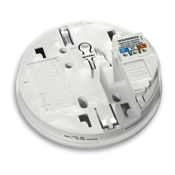
RadioLINK
Alarm Base
Model: Ei168RC
Read and retain carefully for as long as the product is being used. It contains vital information on the operation
and installation. This booklet should be regarded as part of the product.
If you are just installing the Alarm, this booklet must be given to the householder. This booklet is to be given to
any subsequent user.
Instructions
Advertisement
Table of Contents

Related Manuals for Ei Electronics RadioLINK Ei168RC


Summary of Contents for Ei Electronics RadioLINK Ei168RC
- Page 1 RadioLINK Alarm Base Model: Ei168RC Instructions Read and retain carefully for as long as the product is being used. It contains vital information on the operation and installation. This booklet should be regarded as part of the product. If you are just installing the Alarm, this booklet must be given to the householder. This booklet is to be given to any subsequent user.
-
Page 2: Table Of Contents
Contents Page 1. Overview ......................2. Quick install guide ..................3. Installation ....................4. Troubleshooting the RF link ..............5. Checking & maintaining the alarm system ........6. Technical specification ................7. Guarantee ....................8. Limitations of radio communications ........... 9. -
Page 3: Overview
1. Overview This version of the Ei168RC retains all the functionality of previous generations but has some additional features. It can be easily distinguished from previous versions by the blue LED on the side which replaces the amber LED. The primary function of the RadioLINK base is to interconnect all Alarms in the system, i.e. - Page 4 Remote Control Functions Warning: We strongly recommend that a RadioLINK controller be fitted in systems with five or more RadioLINK alarms. This will avoid issues with controlling and silencing systems that have been activated by nuisance (unwanted) alarms Function Description Remote Testing All the Alarms can be tested from a centralised location Remote Locating...
- Page 5 Mixed Wired & RadioLINK System RadioLINK System Hardwired interconnect Wireless interconnect Alarm Controller Alarm Controller In this configuration the alarm controller must be a RadioLINK device. It is not possible to control the system from the hardware interconnect side...
-
Page 6: Quick Install Guide
2. Quick Install Guide The Ei168RC RadioLINK Base must be installed by a qualified electrician. The maximum number of RadioLINK Alarms in each system is 12. If your system has more than 12 Alarms please consult your supplier or contact tech support (see back page). - Page 7 To House Code, insert a small screwdriver INSERT SCREWDRIVER TO into the House Code switch slot and remove TURN ON HOUSE CODE SWITCH immediately when blue light comes on. Repeat this for all alarms in the system. This must be completed as quickly as possible to activate the House Code mode and ensure the system only communicates with itself and not neighbouring...
-
Page 8: Installation
3. Installation Mixing the Live and Neutral connections will damage the alarm. Ensure that the same colours are used throughout the premises for Live, Neutral and Interconnect wires (if used). WARNING Mains operated products should be installed by a qualified electrician as per the requirements for Electrical Installations published as IEE Wiring Regulations –... - Page 9 Orientation of RadioLINK bases Front Wall Front Wall Orientate Latch to point to front wall Antenna Antenna RadioLINK Base RadioLINK Base Orientate all RadioLINK bases in the same direction It is best practice to align all the RadioLINK bases in the same direction as shown in the diagram above.
- Page 10 Fixing & Wiring Select a location complying with the advice in the Smoke/Heat Alarm instruction leaflet. Disconnect the AC mains supply from the circuit that is going to be used. Remove the cover from the terminal block as shown here. Bring the mains wires through the ceiling and thread them through the hole in the rear of the base.
- Page 11 To prevent air draughts affecting smoke or heat entering the alarm it is important to seal the area around the hole in the ceiling with foam or silicon rubber. Screw the base to the ceiling using a single screw for now. The second screw should be inserted at the end of this procedure to secure the base permanently.
- Page 12 Slide the Alarm head onto the base. Connect the mains power to the alarm circuit. Wait 10 seconds and check that the green led on the Alarm cover is on indicating that mains power is present. If the blue light flashes every 10 seconds, remove the alarm and manually depress the rechargeable cell “on”...
- Page 13 A maximum of 12 RadioLink bases may be used in any one system. If your system has more than 12 Alarms please consult your supplier or contact tech support (see back page). House Coding When all the RadioLINK bases have been installed and fitted with Alarms, you are now ready to house code the system.
- Page 14 Check that all the devices have been successfully house coded. This can be done by counting the amount of blue flashes on each RadioLINK base. The number of flashes should correspond to the number of devices in the system. e.g. if the system has 4 Alarms and a remote controller (e.g.
- Page 15 RadioLINK devices instructing them to exit the HOUSE CODE SWITCH house code mode. Note: Some RadioLINK devices do not support the on demand exit house code feature. You may allow them to automatically exit house code after the time period or if you wish, you can do BLUE LIGHT it manually.
- Page 16 Factory reset the house code Sometimes order resolve communication issue, it may be necessary to reset HOUSE CODE SWITCH (factory reset) and house code the system again. To reset each RadioLINK base insert and hold a screwdriver into the house code slot on the base as shown here.
-
Page 17: Troubleshooting The Rf Link
4. Troubleshooting the RF link If when checking the RadioLINK interconnection some of the alarms do not respond to the button test, then: (i) Ensure you have held the test button down for up to 20 seconds and the blue light has come on continuously for 3.5 seconds. - Page 18 (iii) Extend the flexible antenna from the base housing. To do this, the antenna should first be removed from its groove in the base of the unit. Remove the breakaway section in the outer rim and push the antenna in to this groove. For improved signal strength the antenna can be pushed flat or vertical with respect to the ceiling.
-
Page 19: Checking & Maintaining The Alarm System
5. Checking & Maintaining the Alarm System Switching off Mains for long periods If the premises are regularly being left without mains power for long periods the Smoke/ Heat Alarms should be removed from the Ei168RC Bases. In addition to this the rechargeable backup batteries in the Ei168RC must also be switched off in order for them not to become depleted - see page 25. - Page 20 After repair or servicing of any of the systems elements or household electrical works. To test an individual Alarm press and hold the test button until he horn sounds and the red light flashes. This will ensure that the sensor, electronics and sounder are working.
- Page 21 Battery Back-up Check It is important to check that the rechargeable back-up cells in the Ei168RC RadioLINK Base are switched on, charged, and capable of powering the system. We therefore recommend that the functioning of the mains rechargeable cell back-up is checked directly after installation and then at least yearly N.B If the blue light is flashing refer to page 12.
-
Page 22: Technical Specification
Vacuum all around the smoke entry openings in the smoke Alarms to remove any excess dust, lint, cobwebs, etc. 6. Technical Specification 230VAC ~50Hz, 80mA Supply Voltage Battery Back-up Rechargeable Lithium RF Frequency 868.499Mhz C to 40 C (Cat 3) Temp Range Humidity 15% - 95% (Non Condensing) -
Page 23: Guarantee
7. Guarantee Ei Electronics guarantees the Model Ei168RC for 5 years from date of purchase against any defects that are due to faulty materials or workmanship. This guarantee only applies to normal conditions of use and service and does not include damage resulting from accident, neglect, misuse, unauthorised dismantling, or contamination howsoever caused. - Page 24 - at least weekly. This is to determine whether there are sources of interference preventing communication. The radio paths may be disrupted by moving furniture or renovations, and so regular testing will help identify these and other faults, so that they can be rectified (see Section 5).
-
Page 25: Getting The Radiolink Base Serviced
9. Getting the RadioLINK Base Serviced If your RadioLINK Base fails to work after you have carefully read all the instructions and checked that the unit has been installed correctly contact Customer Assistance at the nearest address given at the end of this leaflet. RECHARGEABLE If it needs to be returned for repair or CELL "ON"... - Page 26 Hereby, Ei Electronics declares that this Ei168RC RadioLink Alarm Base, is in compliance with the essential requirements and other relevant provisions of Directive 2014/53/EU. The Declaration of Conformity may be...
- Page 28 Aico Ltd Mile End Business Park, Maesbury Road, Oswestry, Shropshire SY10 8NN, U.K. Telephone: +44 (0)1691 664100 www.aico.co.uk Ei Electronics Shannon Industrial Estate, Shannon, Co. Clare, Ireland. Telephone: +353 (0)61 471277 www.eielectronics.com © Ei Electronics 2016 P/N B17688 Rev4...
Need help?
Do you have a question about the RadioLINK Ei168RC and is the answer not in the manual?
Questions and answers