Ei Electronics Ei168RC Installation Manual
Radiolink alarm base
Hide thumbs
Also See for Ei168RC:
- Installation instructions manual (16 pages) ,
- User manual (24 pages)
Table of Contents
Advertisement
Quick Links
RadioLINK Alarm Base
Ei168RC
Installation Manual
Read and retain carefully for as long as the product is being used. It contains vital
information on the operation and installation. This manual should be regarded as part
of the product.
If you are just installing the Alarm, this manual must be given to the householder. This
manual is to be given to any subsequent user.
1
Advertisement
Table of Contents

Related Manuals for Ei Electronics Ei168RC


Summary of Contents for Ei Electronics Ei168RC
- Page 1 RadioLINK Alarm Base Ei168RC Installation Manual Read and retain carefully for as long as the product is being used. It contains vital information on the operation and installation. This manual should be regarded as part of the product. If you are just installing the Alarm, this manual must be given to the householder. This...
-
Page 3: Table Of Contents
Contents Page 1. Overview ......................2. Quick install guide ..................3. Installation ....................4. Troubleshooting the RF link ..............5. Checking and maintaining the alarm system ........6. Technical specification ................7. Guarantee ....................8. Limitations of radio communications ........... 9. -
Page 4: Overview
The primary function of the RadioLINK base is to interconnect all Alarms in the system, i.e. when one Alarm senses fire, the Ei168RC base attached to that Alarm will transmit an RF signal that will activate the sounders in all the other Alarms. - Page 5 Remote Control Functions Warning: We strongly recommend that a RadioLINK Controller be fitted in systems with five or more RF Alarms. This will avoid issues with controlling and silencing systems that have been activated by nuisance (unwanted) alarms Function Description Remote Testing All the Alarms can be tested from a centralised location Remote Locating...
-
Page 6: Quick Install Guide
2. Quick Install Guide The Ei168RC RadioLINK Base must be installed by a qualified electrician. The maximum number of RF Alarms in each system is 12. If your system has more than 12 Alarms please consult your supplier or contact tech support (see back page). - Page 7 To House Code, insert a small screwdriver into the House Code switch slot and remove immediately INSERT SCREWDRIVER TO TURN ON HOUSE CODE SWITCH when blue light comes on. Repeat this for all alarms in the system. This must be completed as quickly as possible to activate the House Code mode and ensure the system only communicates with itself and not neighbouring systems.
-
Page 8: Installation
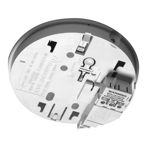
Light Dimmer Circuits This product must not be powered from a light dimmer circuit. The Ei168RC must NOT be connected when the house wiring insulation is being checked with high voltages. i.e. Do NOT use a high voltage insulation tester on the Ei168RC. - Page 9 Orientation of RadioLINK bases Front Wall Front Wall Orientate Latch to point to front wall Antenna Antenna RadioLINK Base RadioLINK Base Orientate all RadioLINK bases in the same direction It is best practice to align all the RadioLINK bases in the same direction as shown in the diagram above.
- Page 10 Fixing and Wiring Select a location complying with the advice in the Smoke/Heat Alarm instruction leaflet. Disconnect the AC mains supply from the circuit that is going to be used. Remove the cover from the terminal block as shown here. Bring the mains wires through the ceiling and thread them through the hole in the rear of the base.
- Page 11 To prevent air draughts affecting smoke or heat entering the alarm it is important to seal the area around the hole in the ceiling with foam or silicon rubber. Screw the base to the ceiling using a single screw for now. The second screw should be inserted at the end of this procedure to secure the base permanently.
- Page 12 Slide the Alarm head onto the base. Connect the mains power to the alarm circuit. Wait 10 seconds and check that the green led on the Alarm cover is on indicating that mains power is present. If the blue light flashes every 10 seconds, remove the alarm and manually depress the rechargeable cell “on”...
- Page 13 A maximum of 12 RadioLink bases may be used in any one system. If your system has more than 12 Alarms please consult your supplier or contact tech support (see back page). House Coding When all the RadioLINK bases have been installed and fitted with Alarms, you are now ready to house code the system.
- Page 14 Check that all the devices have been successfully house coded. This can be done by counting the amount of blue flashes on each RadioLINK base. The number of flashes should correspond to the number of devices in the system. e.g. if the system has 4 Alarms and a remote controller (e.g.
- Page 15 Note: Some RF devices do not support the on HOUSE CODE SWITCH demand exit house code feature. You may allow them to automatically exit house code after the time period or if you wish, you can do it manually. Consult the individual RF device manual for further instructions.
- Page 16 Factory reset the house code Sometimes in order to resolve an RF communication issue, it may be necessary to reset (factory reset) HOUSE CODE SWITCH and house code the system again. To reset each RadioLINK base insert and hold a screwdriver into the house code slot on the base as shown here.
-
Page 17: Troubleshooting The Rf Link
4. Troubleshooting the RF link If when checking the RF interconnection some of the alarms do not respond to the button test, then: (i) Ensure you have held the test button down for up to 20 seconds and the blue light has come on continuously for 3.5 seconds. - Page 18 (iii) Extend the flexible antenna from the base housing. To do this, the antenna should first be removed from its groove in the base of the unit. Remove the breakaway section in the outer rim and push the antenna in to this groove. For improved signal strength the antenna can be pushed flat or vertical with respect to the ceiling.
-
Page 19: Checking And Maintaining The Alarm System
Smoke/Heat Alarms should be removed from the Ei168RC Bases. In addition to this the rechargeable backup batteries in the Ei168RC must also be switched off in order for them not to become depleted - see page 25. (This is sometimes done with holiday homes which are only occupied in the Summer). - Page 20 To test the RF system, press and hold the test button on one of the Alarms. The blue light on the side of the Ei168RC base will come on solid for around 3.5 seconds. Continue to hold the test button until all the Alarms in the system are sounding.
- Page 21 N.B If the blue light is flashing refer to page 12. End of Life (EOL) Check Check the replace unit by date on all Ei168RC bases and attached Alarms. If the date has been exceeded then the device should be replaced.
-
Page 22: Technical Specification
Vacuum all around the smoke entry openings in the smoke Alarms to remove any excess dust, lint, cobwebs, etc. 6. Technical Specification Supply Voltage 230VAC ~50Hz, 80mA Battery Back-up Rechargeable Lithium RF Frequency 868.499Mhz Temp Range C to 40 C (Cat 3) Humidity 15% - 95% RH (Non Condensing) Receiver Category... -
Page 23: Guarantee
7. Guarantee Ei Electronics guarantees this Ei168RC for five years from the date of purchase against any defects that are due to faulty materials or workmanship. If this device should become defective within the guarantee period, we shall at our discretion repair or replace the faulty unit. -
Page 24: Limitations Of Radio Communications
8. Limitations of R adio Communications Ei Electronics radio communication systems are very reliable and are tested to high standards. However, due to their low transmitting power and limited range (required by regulatory bodies) there are some limitations to be considered: (i) Receivers may be blocked by radio signals occurring on or near their operating frequencies, regardless of the House Coding. -
Page 25: Getting The Radiolink Base Serviced
“off” switch to disconnect the rechargeable cells and put both the Alarm and the Ei168RC RadioLINK Base in a padded box and send it to “Customer Assistance and Information” at the nearest address given on the unit or in this leaflet. - Page 26 Block E1 The crossed out wheelie bin symbol that is on your product indicates that this product should not be disposed of via the normal household waste stream. Proper disposal will prevent possible harm to the environment or to human health. When disposing of this product please separate it from other waste streams to ensure that it can be recycled in an environmentally sound manner.
- Page 27 Directive 2014/53/EU. The Declaration of Conformity may be consulted at www.eielectronics.com/compliance Hereby, Ei Electronics declares that this Ei168RC Base is in compliance with the essential requirements of the Radio Equipment Regulations 2017. The Declaration of Conformity may be consulted at www.eielectronics.com/compliance...
- Page 28 Contact Us Aico Ltd Ei Electronics Maesbury Road Shannon Industrial Estate, Oswestry Shannon, V14 H020, Co. Clare, Ireland Shropshire SY10 8NR Telephone: +353 (0)61 471277 Telephone: 01691 664100 www.eielectronics.com www.aico.co.uk © Ei Electronics 2022 P/N B17688 Rev5...
Need help?
Do you have a question about the Ei168RC and is the answer not in the manual?
Questions and answers