Advertisement
Table of Contents
B16073-R2-MCP401RC-UC-ENG
PLEASE NOTE: The MCP401RC is designed for use with the following models of Smoke/Heat/CO Alarms
- Ei161RC, 164RC, 166RC, 141, 144, 146, 151TL, 154TL, 156TLH, 2110, 261ENRC, 261DENRC.
When the black spot on the front face of the MCP401RC is pressed, an alarm signal will be sent along the
interconnect line and all interconnected alarms will sound. The MCP401RC switch element can be reset using
the plastic key supplied.
WARNING: This Manual Call Point should be installed by a qualified electrician in accordance with the
Requirements for Electrical Installations published by the Institute of Electrical Engineers (BS7671 current edition).
A maximum of 4 MCP401RC units can be installed on one system in addition to 12 interconnect alarms.
Disconnect the AC mains power supply from the circuit that is to
1
be used to power the smoke/heat alarms and the MCP401RC.
Install the Smoke/Heat/CO Alarms as per the Installer
2
Instructions supplied with the alarms.
Select a suitable location where the MCP401RC can be easily
3
accessed. The unit should not be exposed to dripping or splashing.
Route the wiring (Live, Neutral, Interconnect/Control and Earth)
4
to the MCP401RC siting location. A minimum 0.75mm
should be used.
5
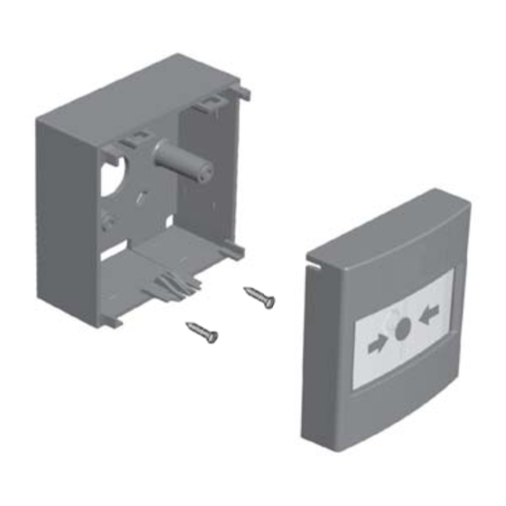
With the 25mm screws provided, fix the mounting box to the wall.
14/10/08
4:24 PM
MCP401RC Manual Call Point
SURFACE MOUNTING BOX
SCREW (2)
3.5 x 25mm
Figure 1
Installation & Wiring
Page 1
FRONT COVER
OPERATING ELEMENT
2
cable
Figure 2
To additional Ei Alarms
Figure 3
if required
(compatible alarms
listed above)
Advertisement
Table of Contents

Related Manuals for Ei Electronics MCP401RC


Summary of Contents for Ei Electronics MCP401RC
- Page 1 - Ei161RC, 164RC, 166RC, 141, 144, 146, 151TL, 154TL, 156TLH, 2110, 261ENRC, 261DENRC. When the black spot on the front face of the MCP401RC is pressed, an alarm signal will be sent along the interconnect line and all interconnected alarms will sound. The MCP401RC switch element can be reset using the plastic key supplied.
- Page 2 It is recommended that the MCP401RC is tested directly after installation and then at least monthly. Test that the MCP401RC call point triggers the alarm(s) by pressing the black spot on the front cover. A striped warning indicator should drop down into view on the front face (visible through the clear plastic window).
Need help?
Do you have a question about the MCP401RC and is the answer not in the manual?
Questions and answers