Ei Electronics Ei600 Series Instruction Manual
Battery powered smoke / heat / multi-sensor fire alarms
Hide thumbs
Also See for Ei600 Series:
- Instructions manual (56 pages) ,
- Instructions manual (54 pages) ,
- Instructions manual (54 pages)
Table of Contents
Advertisement
Quick Links
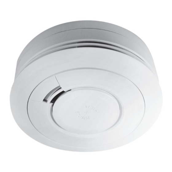
Battery Powered
Smoke / Heat / Multi-Sensor Fire Alarms
Ei600 series
Instruction Manual
Read and retain carefully for as long as the product is being used. It contains vital
information on the operation and installation of your Alarm. The manual should be
regarded as part of the product.
If you are just installing the unit, the manual MUST be given to the householder. The
manual is to be given to any subsequent user.
Advertisement
Table of Contents
Troubleshooting


Need help?
Do you have a question about the Ei600 Series and is the answer not in the manual?
Questions and answers