
Subscribe to Our Youtube Channel
Related Manuals for Dynapac F1000W T4f


Summary of Contents for Dynapac F1000W T4f
- Page 1 OPERATION & MAINTENANCE Paver Finisher F1000W T4f Edit.2 April 2016 4812247169 (A4) ; 4812247170 (A5) Keep for later use in document compartment Valid for:...
- Page 2 www. .com...
-
Page 3: Table Of Contents
Table of contents Preface ..................1 General safety instructions ....................3 Acts, directives, accident prevention regulations ..............3 Warning instructions ......................3 Prohibitive signs ........................6 Protective gear ........................7 Environmental protection ..................... 8 Fire prevention ........................8 Further instructions ......................9 Correct use and application ........... - Page 4 Transportation ........................8 Preparations ........................8 Driving mode ........................11 Loading by crane ....................... 13 Towing ..........................15 Safely parking the vehicle ....................16 D1.1 Operation ................. 1 Safety regulations ........................ 1 Controls ..........................2 Operating panel ........................2 Auxiliary functions ......................25 Left / right remote controls and handsets ................
- Page 5 Engine Error messages ..................... 18 D3.0 Operation ................. 1 Operating elements on the paver ..................1 Operator’s platform ......................1 Seat console ........................1 Operating panel ......................1 Driver's seat ........................2 Batteries ........................2 Battery main switch ......................3 Transport safeguards for the hopper ................
- Page 6 When work is finished ....................21 Malfunctions ........................22 Problems during paving ..................... 22 Malfunctions on the paver or screed ................. 24 E1.0 Set-up and modification ............1 Special notes on safety ....................... 1 Auger ........................... 2 Height adjustment ........................ 2 Auger crossbeam - hydraulic height adjustment ..............
- Page 7 Auger bevel gear (on the RH and LH sides) (4) ..............5 Auger blade (5) ........................6 F5.0 Maintenance - Engine ..............1 Maintenance - engine sub-unit ....................1 Maintenance intervals ....................... 2 Points of maintenance ......................4 Engine fuel tank (1) ......................4 Engine lube-oil system (2) ....................
- Page 8 F9.0 Maintenance - Lubricating Points ..........1 Maintenance - Lubricating points ....................1 Maintenance intervals ....................... 2 Points of maintenance ....................... 3 Bearing points (1) ....................... 3 F10.0 Checks, Decommissioning ............ 1 Tests, check-up, cleaning, stopping ..................1 Maintenance intervals ....................... 2 General observation .......................
-
Page 9: Preface
V Preface Safe operation of the machine requires specific knowledge that is in these operating instructions. The information is provided in a concise, clearly structured form. The in- dividual chapters are arranged in alphabetical order and every chapter starts with page 1. - Page 10 Dynapac (China) Compaction & Paving Equipment Co., Ltd. No. 38, QuanWang Road, WuQing High Tech Industrial Park, Commerce City, CO 80022 301700, Tianjin, China www.dynapac.com...
-
Page 11: General Safety Instructions
The following alerts, prohibitions and instructions refer to the risks to which people, machinery and en- vironment are exposed. Ignoring these instructions, bans and commands may lead to fatal injuries! Furthermore, the Dynapac publication "Directives for the correct and specified application of pavers" shall also be observed. Warning instructions A paving machine has many components and implements that are controlled by a hydraulic system, ei- ther directly or indirectly. - Page 12 Warning: areas of hazard or danger! Not observing the warning instructions may lead to injuries or death! Warning: rotating parts! Rotating parts or transport parts can cause severe injury or death! Perform each operation only with equipment switched off! Attention: electric voltage! All maintenance and repair work on the screed's electrical system must always be carried out by an electrician! Attention: suspended load!
- Page 13 Warning, risk of falling off! Falling can cause severe injury or death! Caution: hazardous batteries! Combustible gas can cause severe burns, blindness or death! Keep sparks and open flame away from batteries. Caution: materials harmful to health and irritating substances! Caution: flammable materials! Caution: gas bottles!
-
Page 14: Prohibitive Signs
Do not spray with water! Do not extinguish with water! Unskilled maintenance is prohibited! Maintenance can be performed by skilled professionals only! Contact the Dynapac service for maintenance assistance! Danger of fire: do not use open flame and no smoking! Do not turn on! -
Page 15: Protective Gear
Protective gear The applicable local regulations may define the use of different protective gear! Observe these specifications! Protect your eyes with goggles! Wear appropriate head protection! Protect your hearing with appropriate ear mufflers! Protect your feet with safety footwear! Always wear tight, conforming working coveralls! Wear visibility vest for good visibility! In case of polluted air, wear respiratory mask! -
Page 16: Environmental Protection
Environmental protection The locally applicable acts, directives and waste disposal regulations shall be ob- served, even if the attention is not specifically directed to these. During cleaning, maintenance and repair operations, pollutants such as: - lubricants (oils, grease) - hydraulic oil - gas oil - coolant - detergents... -
Page 17: Further Instructions
Further instructions Observe the manufacturer's and other instructions! (i.e. the maintenance instructions from the engine manufacturer) Indicates a bottled gas heated design! indicates an electrically heated design! - Page 18 V 10...
-
Page 19: A Correct Use And Application
A Correct use and application The “Guidelines for the Correct Use and Application of Paver” compiled by Dynapac are included in the scope of delivery for the present machine. The guidelines are part of the present operating instructions and must always be followed. Federal, state and local regulations are fully applicable. -
Page 21: B Vehicle Description
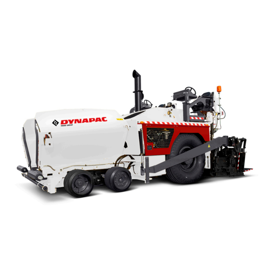
B Vehicle description Application The Dynapac F1000W is a rubber tire fitted paver finisher that is used for laying bituminous mixed ma- terial, roll-down or lean-mixed concrete, track-laying ballast and unbound mineral aggregates for paving foundations. -
Page 22: Description Of Assemblies And Functions
Description of assemblies and functions Standard Item Designation or Optional Material hopper Standard Conveyor Standard Truck push rollers Standard Truck hitch Option Mounting tube for alignment indicator Standard Front tandem axle Standard Rear wheels Standard Levelling cylinder (for paving thickness) Standard Traction arm guide Standard... -
Page 23: Vehicle
Vehicle Construction The Dynapac F1000W is a rubber tire propelled paver built with a welded steel frame on which the power pack, augers, conveyors, hopper and operator positons are mounted. The large drive wheels together with the front tandem shaft jointly compensate the irregularities of the soil and as a result of the screed’s suspension, they guarantee a... - Page 24 The paver is powered by a 6-cylinder, water cooled diesel engine with direct injec- Engine: tion and a turbo charger. Electric starting and belt driven alternator battery charrging is stan- dard. The engine power / rpm is controlled by the engine speed control on either of the consoles.
- Page 25 The paver is equipped with two conveyors driven sepa- Conveyors (Material transfer): rately with pressure from a single pump. The system consists of a single, pressure compen- sated, load sense style, variable displacement, open loop pump driving two fixed volume hydraulic motors.
-
Page 26: Danger Zones
Danger zones In the working areas around the machine (marked in red), there may be a risk of pulling in or crushing during normal operation caused by rotating and conveying elements, or by components in motion. The Danger Zones for the paver are illustrated in the following drawing. Always be aware of Danger Zones. -
Page 27: Technical Data, Standard Configuration
Technical data, standard configuration Dimensions (all dimensions in inches) Carlson EZ IV For screed technical data, refer to the screed operating instructions. -
Page 28: Allowed Angle Of Rise And Slope
Allowed angle of rise and slope max. 15° max. 15° max. 15° Before operating your machine in an inclined position (gradient, slope, lateral inclination) which is above the specified limit value, please consult the customer service department for your machine! Permissible approach angle * with truck hitch Turning circle... -
Page 29: Weights, F1000W
Weights, F1000W Paver finisher without screed approx. 33700 lbs. (15286 kg) Paver finisher with screed: - Carlson EZ IV 1019 (7000 lbs.) approx. 40700 lbs. (18462 kg) - Carlson EZ III 10 (6000 lbs.) approx. 39700 lbs. (18008 kg) - Carlson EZR 10 (8250 lbs.) approx. -
Page 30: Traction Drive/Chassis
Traction drive/chassis Continuously variable hydrostatic drive, with Drive pu mp and engine Transmission Planetary gear Speeds (see above) Drive wheels 18 - 25TH, Rim Width 10” (air filled tires) Steering wheels 16”w - 22”h (solid rubber tires) 2 / 4 wheel hub hydro-motor, freely selected, Front wheel drive variable drive performance, Anti-spin control (o) -
Page 31: Operator Stations
4.11 Operator stations Control consoles Dual swing out operation stations 4.12 Material compartment (hopper) approx. 207ft (5.86m Volume 38.5 in (978mm) Minimum inlet height, center 4.13 Conveyor Conveyor type Dual independent slat conveyor Proportional speed control, both side driven inde- pendently Conveyor control 4.14... -
Page 32: Location Of Instruction Labels And Identification Plates
Location of instruction labels and identification plates Manuals are located behind operator seat B 12... - Page 33 Operation/Maintenance and Safe- ty Manual! Failure to follow the in- structions or heed the warnings could result in injury or death. Contact your Dynapac dealer for replacement of manuals. Proper care is your personal responsibility! Warning! Keep a safe distance from...
- Page 34 Item Decal Description Main battery switch location! NOTE: Follow instructions for using battery main switch! ON/OFF positions for battery main switch. ON - battery connected OFF - battery disconnected Warning! Hot parts or components can cause burns! Keep a safe dis- tance! Hot surfaces can cause burns or per- sonal injury.
- Page 35 Item Decal Description Ultra-low sulphur diesel fuel only. Warning! Crush area! Keep a safe distance when machine is running or moving. Do not work in this area when the machine turns or ma- chine parts move! Crushing can cause severe injury or death!
- Page 36 Identification plate for the paver finisher Item Designation Paver Paver type Mass of the base machine with all standard equipment kg Paver rated power kW Year of manufacturing Product identification number (PIN) The Identification Label is located at the rear of the machine mounted onto the frame near the lifting point.
-
Page 37: 6 En Standards
6 EN standards 6.1 Continuous sound pressure level on the F1000W Wheeled Paver, Cummins QSB 6.7 Tier IV Final Engine. The operator always must use ear protection. The noise level at the operator’s ear varies depending on the materials used for paving and may even rise above 85 dB(A). If no ear protection devices are used, hearing can be impaired. -
Page 38: 6.3 Measuring Point Configuration
6.3 Measuring point configuration Hemispherical measuring surface with a radius of 52.5 ft. (16 m). The machine was at the center. The measuring points had been assigned the following coordinates: Measuring points 2, 4, 6, 8 Measuring points 10, 12 Co-ordinates - 0.27 +0.65... - Page 39 B 19...
-
Page 40: C1.1 Transport
C 1.1 Transport Safety regulations for transportation Accidents can happen when the paver and the screed are not properly prepared for transportation or when transportation is carried out improperly! Reduce both the paver and the screed to their basic widths. Remove all protruding parts (such as the automatic levelling system, auger limit switches, aprons, etc.). - Page 41 The operating panel must be moved to the side of the oncoming traffic and secured in this position. The driving lights must be properly adjusted. Only attachments and extension parts may be transported in the hopper, no material! If necessary, the operator must be assisted by a second person when driving on pub- lic roads –...
-
Page 42: Transportation On Low-Bed Trailers
Transportation on low-bed trailers Reduce the paver and the screed to their basic widths; also remove any attached side plates. The maximum approach angle is indicated in the section entitled “Technical Data“! Check the fill level of the operating fluids so that these do not escape when driving on an incline. - Page 43 Transport on Low Bed Trailers...
- Page 44 Item Operation Select the master console. Close the hopper lids. Engage both hopper transport safeguards. Lift the screed. Retract the screed to the basic width of the paver. Engage both screed transport safeguards. Lift the auger. Turn the range shift selector to zero. Turn the travel speed preselecting regulator to zero.
-
Page 45: Driving Onto The Low-Bed Trailer
Driving onto the low-bed trailer Make sure that there are no persons in the danger area during loading. - Use the work gear and low engine speeds to drive onto the low-bed trailer. - Lower the screed onto wooden blocks on the low-bed trailer. - Turn the switch off. -
Page 46: After Transportation
After transportation - Remove the chains, hooks and all other transport tie-down tools. - Swing the exhaust extension pipe up and secure it. - Lift the screed to the transport position. - Start the engine and drive from the trailer at a low speed. - Park the paver in a secure spot, lower the screed and switch off the engine. -
Page 47: Transportation
Transportation Reduce the paver and the screed to their basic widths; also remove any attached side plates. Preparations - Prepare the paver for transportation (see chapter D). - Remove all overlaying or loose parts from paver and screed (see also Operating instructions for the screed). - Page 48 Transport Preparation...
- Page 49 Item Operation Select the master console. Close the hopper lids. Engage both hopper transport safeguards. Lift the screed. Retract the screed to the basic width of the paver finisher. Engage both screed transport safeguards. Lift the auger. Turn the range shift selector to zero. Turn the travel speed preselecting regulator to zero.
-
Page 50: Driving Mode
Driving mode... - Page 51 Item Operation Turn the selector to position 3. Turn the preselecting regulator to its maxi- mum point. Use the drive lever to regulate the speed. Press the emergency stop button when a dangerous situation arises!
-
Page 52: Loading By Crane
Loading by crane Use only lifting gear that can bear the load. (See chapter B for weights and dimensions). Attachment and loading equipment must meet the conditions of the applicable acci- dent prevention regulations! The vehicle's center of gravity is dependent on the mounted screed. Four lifting eyes (1, 2) are provided for loading the vehicle with a crane. - Page 53 - Remove any attachments and extension parts from the paver and the screed until the basic width has been attained. - Remove all protruding or loose parts(see chapters E and D). - Attach lifting gear to the four attachment points (1, 2). The max.
-
Page 54: Towing
Towing Follow all regulations and apply all safety measures applicable for towing heavy construction machines. The towing vehicle must be capable of securing the paver, even on slopes. Use only approved tow bars! If necessary, remove any attachments and accessories from the paver finisher and the screed until the basic width has been attained. -
Page 55: Safely Parking The Vehicle
Safely parking the vehicle When the paver is parked at a location accessible to the public, it must be secured in such a way that unauthorized persons or playing children cannot damage the vehicle. Remove the ignition key and the main switch (1) and take it with you –... -
Page 56: Operation
D 1.1 Operation Safety regulations Starting the engine, the traction drive, the conveyor, the auger, the screed or the lifting devices can cause injuries or even the death of persons. Make sure before starting any of these devices that no-one is working on, in or be- neath the paver finisher or within its danger area! - Do not start the engine or actuate any controls if this is expressly forbidden! Unless otherwise specified, the controls may only be actuated when the engine is... -
Page 57: Controls
Controls Operating panel Left Hand Operator’s Panel Right Hand Operator’s Panel D 1.1 2... - Page 58 Item Designation Brief description Steering is regulated by the speed of the two drive units. NOTE: Steering wheel -Use the turn signals when turning! -For precise adjustment, see "Straight-ahead travel trimming". Console lights Illuminates the instrument panels when the work lights are switched on. Display for engine information, diagnostic information and Engine Informa- configuration.
- Page 59 PANEL A Left Hand Operator’s Panel Right Hand Operator’s Panel D 1.1 4...
- Page 60 Item Designation Brief description Key positions: 1: Ignition OFF 2: Ignition ON Ignition lock 3: Starter function NOTE: The key can only be removed in position 1. Press in case of emergencies and to indicate when the machine starts to move! Horn NOTE:...
- Page 61 PANEL B Left Hand Operator’s Panel Right Hand Operator’s Panel D 1.1 6...
- Page 62 Item Designation Brief description For switching on the paver finisher functions and for continuously regulating the road speed – forward or reverse. Zero position: starting is possible; engine at idling speed; no traction; protec- tion against inadvertent start. To move the lever, lift the ring (20a). Depending on the position of the drive lever, the following functions can be activated: 1st position:...
- Page 63 PANEL B Left Hand Operator’s Panel Right Hand Operator’s Panel D 1.1 8...
- Page 64 Item Designation Brief description Switches the regeneration function on and off. Toggle switch function: - Toggle the switch up: Regeneration OFF. Neither manual or au- tomatic regeneration of the diesel particulate filter will be allowed. This function should only be enabled if a combustible material is nearby.
- Page 65 PANEL B Left Hand Operator’s Panel Right Hand Operator’s Panel D 1.1 10...
- Page 66 Item Designation Brief description Switches screed vibration on and off. Toggle function: - Toggle the switch to setting 0: Vibration OFF. Vibration - Toggle the switch to setting 1: Vibration ON. ON / OFF NOTE: Speed control (see "Operating instructions for the screed") To select the primary activated operating panel.
- Page 67 PANEL C D 1.1 12...
- Page 68 Item Designation Brief description In the case of an emergency (danger to persons, possible collision, etc.), press the Emergency Stop button! Pressing the Emergency Stop button switches the engine, the drives and the steering system off. Emergency Stop button Paving, lifting the screed or other functions are no longer possible! Do not reset the Emergency Stop Button until the danger is no long- er present! To restart the engine, the button must be pulled out again.
- Page 69 PANEL C D 1.1 14...
- Page 70 Item Designation Brief description Toggles the conveyor and auger (automatic or manual mode) on and off. Toggle switch function: - Toggle the switch forward (away from the operator): Auger + con- veyor are ready for operation (LED ON). Conveyor + auger - Toggle the switch back (toward the operator): Auger + conveyor ON + activation OFF.
- Page 71 PANEL C D 1.1 16...
- Page 72 Item Designation Brief description Hydraulically adjusts the height of the left auger. Toggle switch function: - Toggle the switch forward (away from the operator): Raise auger. - Toggle the switch back (toward the operator): Lower auger. Raise / lower left auger Toggle both switches (raise / lower left + right auger) at the same time to keep the auger crossbeam level! Do not raise or lower the auger until all equipement and persons are...
- Page 73 PANEL D D 1.1 18...
- Page 74 Item Designation Brief description Hydraulically retracts and extends the left extendable part of the screed. Toggle switch function: - Toggle the switch left: Extend screed extension. - Toggle the switch right: Retract screed extension. Extend / retract left screed exten- sion Do not extend or retract the screed until all equipement and persons are away from the machine...
- Page 75 PANEL D D 1.1 20...
- Page 76 Item Designation Brief description Switches between floating screed functions and screed stop. Toggle switch function: - Toggle the switch forward (away from the operator): Screed stop. - "Screed stop" is used to lock the screed hydraulics to prevent the screed from sinking into the paved material when the paver is stationary (intermediate stop).
- Page 77 PANEL D D 1.1 22...
- Page 78 Item Designation Brief description Manually extends and retracts the leveling cylinder when the vehicle is being operated without the automatic leveling system. Toggle switch function: - Toggle the switch forward (away from the operator): Retract or raise leveling cylinder. Left leveling - Toggle the switch back (toward the operator): Extend or lower cylinder leveling cylinder.
- Page 79 PANEL E D 1.1 24...
- Page 80 Item Designation Brief description Lit LED indicates that the diesel particulate filter is becoming filled and a re- generation is needed. The operator could either increase the engine speed and allow the engine to operate until an automatic regeneration is complete or the operator could initiate a manual regeneration.
- Page 81 PANEL E D 1.1 26...
- Page 82 Item Designation Brief description Lit LED indicates that the regeneration system temperature is elevated. During a manual regeneration, the LED turns on during automatic regeneration or when the filter temperature reaches 1247°F. The LED stays on during the regeneration and will then turn off when the Regeneration system temperature temperature falls below 1157°F Regeneration is an extremely hot process.
-
Page 83: Auxiliary Functions
Auxiliary functions D 1.1 28... - Page 84 Item Designation Brief description Controls the working lights. - Toggle the switch up: Turns on the lights. - Toggle the switch down: Turns off the lights. 61 Headlights ON / OFF To prevent the battery from being drained, switch the headlights “ON” only when the diesel engine is running! Activates the Release Agent fluid spraying system.
-
Page 85: Left / Right Remote Controls And Handsets
Left / right remote controls and handsets Item Designation Brief description LEFT remote con- Controls certain functions on the left-hand side of the vehicle trol and various overall functions. RIGHT remote Controls certain functions on the right-hand side of the vehi- control cle and various overall functions. -
Page 86: Left / Right Remote Control
Left / right remote control The left remote controls the left auger and conveyor The right remote controls the right auger and conveyor D 1.1 31... - Page 87 Item Designation Brief description In case of an emergency (danger to persons, possible collision, etc.), press the Emergency Stop button! Pressing the Emergency Stop button switches the engine, the drives and the steering system off. Emergency stop button Paving, lifting the screed or other functions are no longer possible! Do not reset the Emergency Stop Button until the danger is no longer present! To restart the engine, the button must be pulled out again.
- Page 88 The left remote controls the left auger and conveyor The right remote controls the right auger and conveyor D 1.1 33...
- Page 89 Item Designation Brief description Overrides the auger and conveyor function automatic mode. Toggle switch function: - Toggle the switch away from the operator (upward) to run the au- ger and conveyor only using the pile height knobs. The material Right speed manual / sensor will not be used.
- Page 90 The left remote controls the left auger and conveyor The right remote controls the right auger and conveyor D 1.1 35...
- Page 91 Item Designation Brief description Manually extends and retracts the leveling cylinder when the vehicle is being operated without the automatic leveling system. Toggle switch function: - Toggle the switch forward (away from the screed): Retract or raise the leveling cylinder to raise the screed. - Toggle the switch back (toward the screed): Extend or lower the Left leveling the leveling cylinder to lower the screed.
- Page 92 The left remote controls the left auger and conveyor The right remote controls the right auger and conveyor D 1.1 37...
- Page 93 Item Designation Brief description Hydraulically raises or lowers the Berm. Toggle switch function: - Toggle the switch forward (away from the operator): Raises Berm. - Toggle the switch back (toward the operator): Lowers Berm. Berm raise / lower (Option) Before operating the toggle switch, ensure that equipment and per- sons are clear of the machine! Locks and unlocks the Berm.
- Page 94 The left remote controls the left auger and conveyor The right remote controls the right auger and conveyor D 1.1 39...
- Page 95 Item Designation Brief description Hydraulically retracts and extends the left extendable part of the screed. Toggle switch function: - Toggle the switch left: Extend screed extension. - Toggle the switch right: Retract screed extension. Extend / retract left screed extension Before operating the toggle switch, ensure that equipment and per- sons are clear of the machine! To hydraulically retract and extend the right extendable part of the screed.
-
Page 96: Left / Right Handset
Left / right handset D 1.1 41... - Page 97 Item Designation Brief description Manually extends and retracts the leveling cylinder when the vehicle is being operated without the automatic leveling system. Toggle switch function: - Toggle the switch forward (away from the operator): Raises the left screed side arm. Left leveling - Toggle the switch back (toward the operator): Lowers the screed cylinder...
- Page 98 D 1.1 43...
- Page 99 Item Designation Brief description Hydraulically retracts and extends the right extendable part of the screed. Push button function: - Toggle switch left: Retract screed. - Toggle switch right: Extend screed. Extend / retract right screed Before operating the toggle switch, ensure that eqipment and per- sons are clear of the machine! Handset connec- Connects to the left remote control.
-
Page 100: D2.0 Operation
D 2.0 Operation Operation of the graphical terminal Item Designation Brief description - Display for engine information, diagnostic information and Display configuration. - Terminal is controlled by navigation through a set of four soft keys.The keys are context dependent. Soft key Softkeys selection options are displayed above each key and are dependent on the current navigation location within the... -
Page 101: Navigation Using Soft Keys
Navigation using Soft Keys Item Designation Brief description Brightness/Contrast Press to access brightness and contrast settings. Navigate Up Press up to move up through menu items. Navigate Down Press up to move down through menu items. Main Menu Press to go to Main Menu screen. Exit/back one screen Press to go back one screen. -
Page 102: Brightness/Contrast
Brightness/Contrast Adjustment - Adjust brightness and con- trast levels by pressing the far left soft key. This will display brightness contrast soft key bar. The bar will disappear after 3 seconds of inactivity. Main Menu - Start Menu The Main Menu screen is the starting point for configuring the terminal. -
Page 103: Main Menu - Basic Setup
Main Menu - Basic Setup Use the Basic setup screen to set time, language and display units for the terminal. Use Time/Date set date and display style for time and Time/Date date information. Language Use Language to set the system language. Use Units to set speed, distance, pressure, volume, Units temperature and fuel rates and economy settings. -
Page 104: Time / Date
Main Menu - Basic Setup -Time / Date Use Time/Date screen to set Time, Date, calendar style and time style. Use up, down select and next soft keys to navigate. Main Menu - Basic Setup -Language Use Language screen to se- lect program language. -
Page 105: Main Menu - Basic Setup
Main Menu - Basic Setup -Units Use the up, down, select and next soft keys to define unit measurements. Speed km/h, mph Distance km, mi Pressure kPa, bar, Ibs/ sq in Volume l, gal, imp gal Temperature °C, °F Fuel Economy 1/100km, mpg, mpig Fuel Rate l/h, g/h, ig/h... -
Page 106: Main Menu - Diagnostics
Main Menu - Diagnostics Use the Diagnostics screen to display current system in- formation, view and monitor fault logs and display all J1939 devices connected to the graphical terminal. D 2.0 7... -
Page 107: System Info
Main Menu - Diagnostics -System Info The system info screen dis- plays the hardware system serial number, current soft- ware version, current system version and node number. Only information is displayed in the System Info window. No changes can be made. Main Menu - Diagnostics -Fault Log Fault information is saved... -
Page 108: Main Menu - Diagnostics
Main Menu - Diagnostics -Fault Log Active and Previous Faults Selecting Active Faults in the Fault Menu will display all ac- tive faults on the CAN net- work. Selecting Previous Faults in the Fault Menu will display all previously active faults on the CAN network. - Page 109 Main Menu - Diagnostics -Fault Pop-Up Alarms When a fault is detected on the CAN network, a flashing red warning alarm will be ac- tivated and a fault informa- tion pop-up window will be displayed listing current fault information. Warning lights will flash when a popup alarm occurs and will stay flashing until ac- knowledged.
-
Page 110: Device List
Main Menu - Diagnostics -Device List The Device list page will list all J1939 devices and ad- dresses that are currently be- ing monitored on the network. D 2.0 11... -
Page 111: Quick Data
Main Menu - Diagnostics -Quick Data The Quick Data function allows se- lected signals to be monitored in a scrollable single view display. To select signals for display, press the far right soft key. Quick Data softkey Scroll through signal list using the up and down arrow soft keys and select/de-select signals for Quick View monitoring by pressing the far... -
Page 112: Start Display
Start Display Appears at system start. Model Select Use the scroll buttons to select the appropriate paver movel. Once the check mark is on the correct model, press “OK”. D 2.0 13... -
Page 113: Display 01
Display 01 Display menu - Vehicle Speed (1) in fpm. - Engine RPM (2) in rpm - with bar chart. - Diesel tank filling (3) in % - with bar chart. - Engine Coolant Temperature(4) in °F. Display 02 Display menu - Hydraulic Oil Tempersature (1) in °F. -
Page 114: Active Faults Display
Active Faults Display Appears when a fault occurs. - To see a list with active faults, first use button 2 or 3 from the current screen and go to Active Fault Screen, then press button 4 to get into the Active Fault Screen. -
Page 115: Warnings Display
Warnings Display Appears due to faulty machine op- eration. - Line (1): Actual displayed Warn- ing of (x) active Warnings. Code number is displayed - Scroll between the active warn- ings by using buttons 2 or 3. - Leave Warning display by using button 1 Warning Codes Situation... - Page 116 Situation Code Display Message Open: 25 UltrasAugerRH_Open, RH auger ultrasonic sensor open/short Short: 24 UltrasAugerRH_Short Open: 27 Conv_PotLH_Open, LH conveyor potentiometer open/short Short: 26 Conv_PotLH_Short Open: 29 Conv_PotRH_Open, RH conveyor potentiometer open/short Short: 30 Conv_PotRH_Short Open: 31 AugerPotLH_Open, LH auger potentiometer open/short Short: 30 AugerPotLH_Short Open:33...
-
Page 117: 1.2 Engine Error Messages
1.2 Engine Error messages D2.0.18... - Page 118 D2.0.19...
- Page 119 D2.0.20...
- Page 120 D2.0.21...
- Page 121 D2.0.22...
- Page 122 D2.0.23...
- Page 123 D2.0.24...
- Page 124 D2.0.25...
- Page 125 D2.0.26...
- Page 126 D2.0.27...
- Page 127 D2.0.28...
- Page 128 D2.0.29...
- Page 129 D2.0.30...
- Page 130 D2.0.31...
- Page 131 D2.0.32...
- Page 132 D2.0.33...
- Page 133 D2.0.34...
- Page 134 D2.0.35...
- Page 135 D2.0.36...
- Page 136 D2.0.37...
- Page 137 D2.0.38...
- Page 138 D2.0.39...
- Page 139 D2.0.40...
- Page 140 D2.0.41...
- Page 141 D2.0.42...
- Page 142 D2.0.43...
- Page 143 D2.0.44...
- Page 144 D2.0.45...
- Page 145 D2.0.46...
- Page 146 D2.0.47...
- Page 147 D2.0.48...
- Page 148 D2.0.49...
- Page 149 D2.0.50...
- Page 150 D2.0.51...
- Page 151 D2.0.52...
- Page 152 D2.0.53...
- Page 153 D2.0.54...
- Page 154 D2.0.55...
- Page 155 D2.0.56...
- Page 156 D2.0.57...
- Page 157 D2.0.58...
-
Page 158: D3.0 Operation
D 3.0 Operation Operating elements on the paver Operator’s platform Seat console The seat console can pivot beyond the outer edge of the vehicle, providing the driver with a better view of the paving area in this position. - Release the platform lock (1). - Swing the seat console to the desired position. -
Page 159: Driver's Seat
Driver's seat To avoid injury, the individual seat settings should be checked and adjusted before starting the vehicle. After the adjustments are set, check the seat to ensure it does not move out of adjustment. - Se at forward and back adjustment (1): The seat can be moved forward or it can be moved back. -
Page 160: Battery Main Switch
Battery main switch The main switch interrupting the circuit between the battery and the main fuse is located above the battery pack. See chapter F for fuse locations and fuse order. - To switch the ignition off, turn the key (1) to the left and pull it out. -
Page 161: Transport Safeguards For The Hopper
Transport safeguards for the hopper Before parking or transporting the paver, the hop- per halves must be pivoted upwards and the trans- port safeguards for the hopper must be inserted. - Insert the safeguards on both sides of the ma- chine (1) into the pinning hole. -
Page 162: Paving Thickness Indicator
Paving thickness indicator The Paving Thickness Indicator scales are locat- ed on the left and right sides of the vehicle. - The Paving Thickness Indicator (1) shows the setting on the Scale (2). - In normal paving situations, the same paving thickness should be set on both sides of the vehicle! Avoid different settings on the scales as this will produce un-even pavement. -
Page 163: Release Agent System
Release Agent System Used to spray the parts coming into contact with asphalt with a separator emulsion. NOTE: Check local regulations concerning use of clean- ers and use of solvents! - Pull hose (1) out of the guide until there is an audible click. -
Page 164: On/Off Switch Of Working Lights (1)
On/Off switch of working lights (1) Toggle switch (1) to switch on all installed working lights. On/Off switch hazard flasher (2): Activate switch (2) to switch on installed flasher. Warning Beacon NOTE: The function of the warning beacon must be checked daily before starting work. -
Page 165: Conveyor Limit Sensors
Conveyor limit sensors The ultrasonic conveyor limit sensors control the material flow at the respective conveyor half. The conveyors should stop when the material has roughly reached the area below the auger tube. NOTE: This requires that the auger height has been ad- justed correctly (see chapter E). -
Page 166: D4.0 Operation
D 4.0 Operation Preparation of operation Required equipment and tools To avoid delays on site, check before starting work whether or not the foll equipment and tools are present: - Wheel loader for transporting heavy extendable parts - Diesel fuel - Engine oil and hydraulic oil, lubricants - Separating agents (emulsion) and manual injector - Shovel and broom... -
Page 167: Before Starting Work
Before starting work (in the morning or when starting paving) - Follow the safety instructions. - Check personal protective equipment. - Take an inspection walk around the paver and check for leaks and damages. - Install parts removed for transportation or for the night. - Perform the check according to the ”Checklist for the machine operator”... - Page 168 Check! How? For larger working widths, the walkway Auger covers plates must be extended and the auger tunnels must be covered. For larger working widths, the walkway plates must be extended. Hinged walkway plates must be swung Screed covers and walkways down.
- Page 169 D 4.0 4...
-
Page 170: Starting The Paver
Starting the paver Before starting the paver Before starting the diesel engine and beginning operation, the following steps must be performed: - Daily maintenance of the paver (see chapter F) Check the operating hours counter to determine whether or not additional mainte- nance work (such as monthly or yearly maintenance) must be performed. - Page 171 D 4.0 6...
-
Page 172: Jump Starting
Jump starting The engine can be started with the help of an external power source if the batteries are low and the starter no longer turns. Suitable power sources are: - Other vehicles with a 24 V system - Additional 24 V battery - Start device that is suitable for jump starting (24 V/90 A). - Page 173 D 4.0 8...
-
Page 174: After Starting
After starting To increase the engine speed: - Set selector (21) for traction drive / engine to position 2. Let the paver warm up for about 5 minutes if the engine is cold. Read and follow Chapter D2 of this manual for possible warnings on the graphical ter- minal! D 4.0 9... - Page 175 D 4.0 10...
-
Page 176: Transport Operation
Transport Operation Lifting and securing the screed - Raise the screed using switch (52). - Center the levelling cylinders using the switches (54)/(55). The remote control must be connected and this function must be set to “Manual“. - Raise the auger crossbeam using switches (47)/(48). Engage both screed transport safeguards to secure the screed in the raised position. -
Page 177: Preparations For Paving
Preparations for paving Releasing agent Spray the parts coming into contact with asphalt (hopper, screed, auger, push roller) with a separator emulsion. Do not use diesel fuel as it dissolves the bitumen. Screed heater Switch the screed heater “On” for about 15–30 minutes (depending on the ambient temperature) before paving begins. - Page 178 D 4.0 13...
-
Page 179: Loading/Distributing Material
Loading/distributing material - Open the hopper with switch (15). Have the truck back short of the paver and pull the paver against the truck tires. Guide the truck driver when dumping the material mix. - Set the switch (45) of the auger and conveyor to the “ON” position. - Set both switches (46) of the auger and conveyor to “AUTO“... - Page 180 D 4.0 15...
-
Page 181: Starting For Paving
Starting for paving Set the switches, levers and controls listed below to the specified positions when the screed has reached its operating temperature and a sufficient amount of material lies in front of the screed: Item Switch Position Selector position 1 Preselector approx. -
Page 182: Check During Paving
Check during paving The following points must be constantly observed during paving: Paver function - Screed heater - Vibration and/or tamper - Engine oil and hydraulic oil temperature - The screed parts must be retracted and extended in time when obstacles are in the way. - Uniform material transport and distribution or supply to the screed;... - Page 183 D 4.0 18...
-
Page 184: Interrupting/Terminating Operation
Interrupting/terminating operation During breaks (i. e . the material supply truck is late) - Determine the approximate duration. - When the material’s temperature drops below the minimum paving temperature, run the paver empty and create an edge like the end of a layer. - Set the drive lever (20) to the center position. - Page 185 51 55 D 4.0 20...
-
Page 186: When Work Is Finished
When work is finished Run the paver empty, then bring it to a stop. Turn drive lever (20) to the center position. Move the preselector (12) and selector (21) to minimum position. Switch off conveyor + auger (45), vibration (27), and lights (25) and exhaust system (24). Lift the screed by using switch (52). -
Page 187: Malfunctions
Malfunctions Problems during paving Problem Cause: - change in the material temperature, segregation - wrong material composition - incorrect operation of the roller - incorrectly prepared foundation - long idle standing times between loads - grade control reference line is not suitable - grade control jumps to the reference line - grade control toggles between up and down Wavy surface... - Page 188 Problem Cause: - temperature of the material Cracks in the layer - cold screed (center strip) - bottom plates are worn or warped - wrong crowning - temperature of the material - screed extendable parts are incorrectly installed Cracks in the layer - limit switch is not correctly set (outer strip) - cold screed...
-
Page 189: Malfunctions On The Paver Or Screed
Malfunctions on the paver or screed Malfunction Cause: Remedy See operating instructions for At the diesel engine Diverse the engine See ”External starting” Batteries drained Diesel engine does (start assistance) not start Other see ”Towing” Tamper is obstructed by Properly heat the screed cold bitumen Hydraulic oil level in the Fill with oil... - Page 190 Malfunction Cause: Remedy Control valve is defective Replace Hoppers lowers Leaking seals in the inadvertently Replace hydraulic cylinder Oil pressure too low Increase the oil pressure Leaking seal Replace Screed cannot be Screed relieving or Switch must be in the center lifted charging is switched on position...
- Page 191 Malfunction Cause: Remedy Replace Traction drive fuse (Fuse holder is on the operating defective panel) Check potentiometer, cables, Power supply is interrupted connectors; replace if necessary Traction drive monitoring Replace defective Traction does not Electro-hydraulic servo unit work Replace the servo unit of the pump is defective Check and adjust if necessary Check the suction filter;...
-
Page 192: Set-Up And Modification
E 01 Set-up and modification Special notes on safety Inadvertently starting the engine, the traction drive, the conveyor, the auger, the screed or the lifting units can be dangerous. Unless specified otherwise, work may only be performed when the engine is not running! - To protect the paver against inadvertent starting: Set the drive lever to the center position and set the preselector to zero;... -
Page 193: Auger
Auger Height adjustment Depending materials, when working with layer thicknesses of up to 10 in. (25.4 cm), the height of the distribution auger (1) – measured from its bottom edge – should be around 5 cm (2 inches) above the material layer thick- ness (depending on its mix of materials). -
Page 194: Auger Extension
Auger extension Depending on the type of screed, the most diversified working widths can be reached. Auger and screed extension must match. See the operating instructions for the ap- propriate screed, chapter ”Set-up and modification”, especially: – Screed extension chart, –... -
Page 195: Mounting Extension Parts
Mounting extension parts - Loosen the clamping screws (6) on the support tube. Then turn in the center expanding screw (5) to expand the clamping joint. - Pull the telescopic tube out of the sup- port tube (7). - Mount the required extension parts. NOTE: Observe the guide groove of the spline! Make sure that the shaft end is clean! -
Page 196: Mounting Support Tube Extensions
Mounting support tube extensions If the working width exceeds 23 ft. (7.01 m.), an auger crossbeam extension must be mounted. The support tube extension of the auger cross- beam consists of two halves (8) and is attached to the existing support tube by using a total of 5 screws. -
Page 197: Installing Tunnel Plates
Installing tunnel plates To ensure an optimum material flow – especially in the case of large paving widths – so-called tunnel plates (11) must be installed. They are located directly in front of the auger distributor – conjunction with the auger – are an ideal system for conveying the material. -
Page 198: Installing Additional Braces
Installing additional braces When operating with width of more than 25 ft. (7.62 m.) the augers must be provided with an additional support. To do so, attach two braces on both the left-hand and the right-hand side, between the tunnel plate support and the bracket provided on the paver. The braces are included in the scope of delivery for this working width. -
Page 199: Screed
Screed The operating instructions for the screed explains what is required for mounting, setting up and extend- ing the screed. Electrical connections Ensure the following connections have been made once the screed has been mounted and set up: Remotes from screed to paver The screed plugs into the back of the paver sock- et (15). -
Page 200: Left Hand Conveyor Sensor Control
Left hand conveyor sensor control The conveyor sensor connects to the DC control box. The control box is connected to the right re- mote by a cable through the rear bulkhead. The remote then sends the signal from the sensor to the paver thru the cable shown. -
Page 201: Auger Chart
Auger Chart E 01 10... -
Page 202: F1.0 Maintenance
F 1.0 Maintenance Notes regarding safety Maintenance work: Maintenance work may only be carried out when the engine is not running. Secure the paver and the attachments against inadvertent starting before beginning any maintenance work: - Set the drive lever to the center position and the speed preselector to zero. - Remove the ignition key and the battery main switch. - Page 203 F 1.0 2...
-
Page 204: F2.1 Maintenance Overview
F 2.1 Maintenance Overview Maintenance overview 10.0... - Page 205 Maintenance required after the following service hours Assembly Chapter q q q Conveyor F3.0 q q q Auger F4.0 q q q q Engine F5.0 q q q Hydraulics F6.0 Travel drive, steering F7.1 q q q Electronics F8.1 Lubrication points F9.0 Checking/decommis- F10.0...
-
Page 206: F3.0 Maintenance - Conveyor
F 3.0 Maintenance - Conveyor and Hopper Maintenance - Conveyor and Hopper F 3.0 1... -
Page 207: Maintenance Intervals
Maintenance intervals Interval Points of maintenance Remark - Checking the tension of the conveyor chain q - Adjusting the tension of the conveyor chain - Conveyor chain - Check chain q - Conveyor chain - Replace chain - Clean Conveyor chain supports - Conveyor tensioning sprocket - Lubricate grease zert - Conveyor bearing -... -
Page 208: Chain Tension Of The Conveyor (1)
Points of maintenance Chain tension of the conveyor (1) Checking the track tension: For daily inspection look straight through under the bumper. The chain must not hang below the bottom edge of the bumper. Should readjustment be necessary, measure the slack unloaded from the bottom edge of the floor plate to the bottom edge of the chain (see the figure). - Page 209 - Conveyor chain - Conveyor chain guards - Conveyor plates - Conveyor chain tensioning sprockets - Conveyor gear drive sprockets Contact your Dynapac customer service representative for support during maintenance, repair and the replacement of worn parts! F 3.0 4...
- Page 210 Conveyor tensioning sprocket bear- ings (2) The tensioning sprocket bearings for the convey- ors are lubricated at the grease zerts (A) located behind the crossbeam. The center bearings are lubricated at the outer lubricating grease zerts. Pump 5 strokes of grease with a grease gun.! Conveyor bearing block (1) The center conveyor bearing block is lubricated with the grease zert (B) located insided the rear...
-
Page 211: Conveyor Drive - (5) Drive Chains
Conveyor drive - (5) drive chains Checking for chain tension: - In normal conditions, the chain has to have ap- proximately .4 to .6 inch (10 - 15 mm) of play. To set the chain tension: - Loosen the locking bolts (A) and the lock-nut (B). -
Page 212: Conveyor Drive - (6) Planetary Drive (Left/Right)
Conveyor drive - (6) planetary drive (left/right) - To check the oil level, unscrew the in- spection plug (A). NOTE: For proper oil level, the oil must be at the lower edge of the inspection port or a little oil flows from the hole. - Page 213 - Conveyor chain - Conveyor chain guards - Conveyor plates - Conveyor chain tensioning sprockets - Conveyor gear drive sprockets Contact your Dynapac customer service representative for support during maintenance, repair and the replacement of worn parts! F 3.0 8...
-
Page 214: F4.0 Maintenance - Auger
F 4.0 Maintenance - Auger Maintenance - Auger sub-unit I F 4.0 1... -
Page 215: Maintenance Intervals
Maintenance intervals Interval Points of maintenance Remark - Auger - outer bearing Lubrication - Auger central bearing Lubrication - Auger drive neck bearing Lubrication - Auger bevel gear oil level check - Auger bevel gear topping up the oil - Auger bevel gear oil change Auger wear plates (auger seg ments)-... - Page 216 Points of maintenance Auger - outer bearing (1) The grease zerts (A) are located on each side on the top of outer bearing. These zerts must be lubricated each time work is finished. The outer bearings of the auger must be lubricated when hot, so that the eventual bitumen residue is expelled.
- Page 217 Auger - drive gear neck bearing (3) Remove the hexagonal plug (A) in the neck of the drive. Replace the plug un- der it with an extended grease zert 10x1. Use a grease gun to pump about 10 strokes of grease. Next, unscrew grease...
- Page 218 Auger bevel gear (on the RH and LH sides) (4) - To check the oil level unscrew the in- spection / filling plug (A). NOTE: The oil level is full when the oil is at the lower edge of the inspection port or a lit- tle oil flows from the hole.
- Page 219 Auger blade (5) If the surface of the auger blade (A) becomes sharp-edged, the diameter of the auger is reduced and the blades (B) have to be replaced. - Remove the bolts (C), washers (D), nuts (E) and auger blade (B). Sharp-edged parts can cause personal injury! Auger blades must be installed with out any play and the contact surfaces must be dirt-free! - Install the new auger blade (B);...
-
Page 220: F5.0 Maintenance - Engine
F 5.0 Maintenance - Engine Maintenance - engine sub-unit 1 - Fuel Tank (Not Shown) 4 - Air Cleaner (Not Shown) 5 - Radiator (Not Shown) F 5.0 1... - Page 221 In addition to these Maintenance Instructions, the Maintenance Instructions of the en- gine manufacturer must always also be observed. All other maintenance work and in- tervals noted in these instructions are also binding. Maintenance intervals Interval Points of maintenance Remark - Fuel tank Check the filling level - Fuel tank...
-
Page 222: Points Of Maintenance
Interval Points of maintenance Remark - Engine air filter Check the air filter - Engine air filter Empty the dust collecting bin - Engine air filter Clean / Replace the filter car- tridge - Engine cooling system Inspection the radiator fins - Engine cooling system Clean the radiator fins - Engine cooling system... -
Page 223: Engine Fuel Tank (1)
Points of maintenance Engine fuel tank (1) NOTE: There is one fuel tank on each side of the machine! - Check the fuel level on the operating panel (check display). Fill the fuel tank before each work shift to prevent the fuel system of running dry. If the tank is ran dry, the system will have to be bled causing work delay. -
Page 224: Engine Lube-Oil System (2)
Engine lube-oil system (2) Check oil level Check that the oil level is between the maximum and minimum lines on the dip- stick (A). NOTE: Check the oil level with the paver parked on a flat surface! Some state and federal agencies in the United States of America have determined that used engine oil can be carcinogenic and can cause reproductive toxicity. - Page 225 Oil change: Do not drain the oil when the engine is cold. As the oil cools, suspended waste particals settle on the bottom of the oil pan. The waste particles are not removed with the draining cold oil. Drain the crankcase with the engine stopped.
-
Page 226: Engine Fuel System (3)
Engine fuel system (3) The fuel filter system consists of two filters: - Pre-filter (A) with water separator (located in the engine compartment). - Main filters (B) Pre-filter - drain the water Empty the condensation prior to every engine start or when the engine electronics indicate a fault. - Page 227 Main filter replacement: - Loosen the filter (B) and clean the surface where the new filter will mount. - Apply a thin coat of oil to the gasket of the new filter. - Tighten the filter by hand. NOTE: After mounting the filter, check it for proper tightness. Do not fill the fuel filters with fuel before installing them.
-
Page 228: Engine Air Cleaner (4)
Engine air cleaner (4) The function of the engine air cleaner is to filter the air taken into the engine through the engine’s air intake. The engine air cleaner is the dry type with two elements: a primary element that is cleanable and replacable, and a safety element that should only be replaced and not cleaned. - Page 229 To remove the filter cartridges: - Open the latches to remove the cover. - Remove the primary filter and then the filter cartridge (B). NOTE: Clean the filter cartridge and replace at least once per year. - Blow out with dry pressure air (max. 30 psi / 2.07 bar) from inside blowing out. In case of an urgency, tap the cartridge to remove dust.
-
Page 230: Engine Coolant System (5)
(A) on the coolant tank. Check the coolant level at the site-glass (B) inside the fuel fill door. Do not mix coolants. Only use Dynapac approved coolants. Do not add cold coolant to a hot engine. Engine castings can be damaged. Allow the engine to cool to 120°... - Page 231 - Once drained, dispose of the coolant fluid in an appropriate manner. Coolant is toxic. Keep away from children and pets. Dispose of in accordance with federal, state and local environmental regulations - Close the drain valve. - Fill the radiator with a 50/50 mix of water and ethylene glycol or propylene glycol antifreeze. - Install the radiator cap.
-
Page 232: Engine Drive Belt (6)
Engine drive belt (6) Check drive belt/replacement Under normal operating conditions, the engine drive belt(s) should be inspected daily. Belt dam age can be caused by incorrect size or length, pulley misalignment, incorrect installation, severe operating environment and oil or grease on the belt(s). -
Page 233: Maintenance - Def Tank
Maintenance – DEF tank Clean the DEF tank Drain the tank. Remove the Multifunction Head Unit from the tank. Inspect the debris saturation of the DEF suction filter to determine if the filter needs to be replaced. If the filter is damaged or dirty, replace the filter. Rinse out the interior of the DEF tank using an ordinary hose or pressure washer. - Page 234 mounting base until it is completely seated in the tank bore. Position the retaining ring on Head unit and install the retention screws using the T25 Torx wrench. Recommended torque on screws is 20-30 in-lbs (2.26-3.38Nm) DEF suction filter DEF Suction Filter is located at the bottom of the Multifunction Head Unit assembly thus requiring the head unit to be removed from the DEF reservoir.
- Page 235 F 5.0 16...
-
Page 236: F6.0 Maintenance - Hydraulic System
F 6.0 Maintenance - Hydraulic System Maintenance - hydraulic system 5 Hydraulic Hoses - Not Shown F 6.0 1... -
Page 237: Maintenance Intervals
Maintenance intervals Interval Points of maintenance Remark - Hydraulic oil tank Check the oil level - Hydraulic oil tank Fill with oil - Hydraulic oil tank Oil change and cleaning - Hydraulic oil tank Check the maintenance indicator - Hydraulic oil tank Intake / return q - Change the hydraulic filter - High pressure filter... -
Page 238: Hydraulic System
Hydraulic System A paving machine has many components and implements that are controlled by a hy- draulic system, either directly or indirectly. Before working on or inspecting any part of a paving machine, it is important that the individual knows how the components move and are controlled by the hydraulic system components including the respective control circuits. -
Page 239: Points Of Maintenance
Points of maintenance Hydraulic oil tank (1) - Oil level check at sight level gauge (A) on the side of the tank. NOTE: View the sight level gauge by the open- ing fuel tank flap on the L.H. side of the machine. - Page 240 To change the oil: - To drain the hydraulic oil unscrew the drain plug (C) at the bottom of the tank. - Collect the oil in an appropriate contain- er using a funnel. - After draining, add a new seal ring and then screw the plug back into place.
-
Page 241: Suction/Return Flow Hydraulic Filter (2)
Suction/return flow hydraulic filter (2) Change the filter at the intervals specified or when the maintenance indicator (A) is at the red mark or when changing hydraulic oil. When inspecting the maintenance indicator, the hydraulic oil must be at least 175° F (80° C). When changing the hydraulic oil also change the filter. -
Page 242: Venting The Filter
Venting the filter: - Fill the open filter case with hydraulic oil to just below the upper rim. - Should the oil level drop, fill with oil. The oil level slowly lowering by about 1/4 in./min. (1 cm/min) is normal! - When the oil level remains steady, mount the assembled unit with the new filter cartridge, carefully into the housing and tighten the locking screws of the lid (B). - Page 243 High pressure filters (3) Replace the auger charge filter (A) cartridge and conveyor pump / work system filter (B) when the maintenance indicator on top of the filter cartridge head turns “red”. - Unscrew filter housing. - Remove the filter cartridge. - Clean the filter housing.
-
Page 244: Pump Distribution Gear (4)
Pump distribution gear (4) - Check the Oil level at the sight glass (A) (at the side of the distribution box). NOTE: The oil level must be up to the center of the sight glass. To add oil: - Unscrew the plug (B). - Add oil until the sight glass (A) shows the cor- rect fluid level. - Page 245 Change the oil when the engine is at operating temperature. - Place the end of the hose in an appropriate container and catch the oil. - Open the shut-off valve and let the oil drain completely. - Shut off the valve, remove the hose and return the cover cap.
-
Page 246: Hydraulic Hoses (5)
Hydraulic hoses (5) Frayed or damaged hoses can break instantly causing hot hydraulic fluid to spray causing se- vere burns. Always replace worn or damage hos- es immediately. Hot oil or components can burn. Oil must be at normal operation temperature when draining. Avoid con- tact with hot oil or components. - Page 247 F 6.0 12...
-
Page 248: F7.1 Maintenance - Travel Drive, Steering
F 7.1 Maintenance - Travel Drive, Steering Maintenance - travel drive, steering... - Page 249 Maintenance intervals Interval Points of maintenance Remark - Rear wheels - wheel mounting nuts - Front wheels - wheel mounting nuts - Check the oil level of the planetary gear - Check the oil level of the planetary gear (drive) - Planetary gear (drive) - Change the oil - Air pressure (drive wheels) -...
-
Page 250: Front Wheels (With Front Wheel Drive)
Points of maintenance Wheel mounting nuts (1) Rear wheels The 16 wheel mounting nuts have to be tighten in the described order with a torque of 375 ft. lbs. ( 508 Nm) dry thread. Front wheels (with front wheel drive) The 10 wheel mounting nuts have to be tighten in the described order with a torque of 400 ft. -
Page 251: Planetary Gear (2)
Planetary gear (2) Care must be taken to ensure fluids are contained during performance of inspection, maintenance, testing, adjusting and repair of the paver. Be pre- pared to collect the fluid with suitable containers before opening any compartment or disassembling any component containing fluids. - Page 252 To change oil: Change the oil when the engine is at operating temperature. Hot oil or components can burn. Oil must be at normal operation temperature when draining. Avoid con- tact with hot oil or components. Make sure that no pollution or foreign matter gets into the drive. - Stop the machine so that the “TOP”...
-
Page 253: Air Pressure (Driving Wheels) (3)
Air pressure (driving wheels) (3) Check/adjust the air pressure: The required tire pressure is 45 psi (pounds per square inch) for each tire. Check the air pressure at the valve and adjust as required. -
Page 254: Places Of Lubrication (4)
Places of lubrication (4) Steering The grease zert is located on the right side wall and the steering linkage is supplied with grease through a lubrication line. Grease Points Pump the grease gun 5 times into the zert at the end of the lubrication line for the steering linkage. - Page 255 Gear- lubrication materials (5) Lubricants and fuels NOTE: Use only the lubricants listed or the equivalent quality lubricants. Use only clean containers for adding oil or fuel. Take into account the filling volumes (see the section “Filling volumes“). Low quality oil or lubricant causes faster wear and the failure of the machine. Mixing of synthetic and natural oils is explicitly prohibited!
-
Page 256: F8.1 Maintenance - Electronic System
F 8.1 Maintenance - Electronic System Maintenance - Electronic system... -
Page 257: Maintenance Intervals
Maintenance intervals Interval Maintenance point Note Check the charge level of the batteries, replace if necessary Apply grease to battery terminals q Electric fuses Maintenance Maintenance during the running-in period... -
Page 258: Points Of Maintenance
Points of maintenance Batteries (1) Maintenance of batteries NOTE: The batteries equipped with the paver are “Maintenance Free” batteries. When batteries can no longer hold a charge, they must be replaced. The battery terminal clips must be free of corrosion (ox- ide) and protected with grease. -
Page 259: Electric Fuses / Relays (3)
Electric fuses / relays (3) Main fuses (A) Fuse No. Description Rating (A) Main Battery Fuse Alternator Fuse Key Switch Line Fuse Air Heater Fuse ECM Power Supply Fuse... -
Page 260: Fuses In Terminal Box (B)
Fuses in terminal box (B) Fuse No. Description Rating (A) Propel Controller Emergency Stop ECM Key Switch Signal Key Switch Power DP200 Display Power Horn Power Supply Start Prevention Relay, Hour Meter Propel Devices Console Select Switch and Parking Brake Auger Conveyor On/Off and Auto/Manual Switch Auger Raise/Lower Tow Arm Levelling Control... - Page 261 Fuse No. Description Rating (A) Truck Hitch and Wash Down Screed Power Supply Screed Power Supply Front Wheel Assist Auger/Conveyor Controller Power Supply Auger/Conveyor Cleaning/Fast Fill Switch Auger/Conveyor Ultrasonic Sensors Auger/Conveyor Override Switch Power...
-
Page 262: Relays In Terminal Box (C)
Relays in terminal box (C) Relay No. Description Starter Anti Start Circuit Emergency Stop Circuit Intake Air Heater Auger / Conveyor ON / OFF Auto Mode Enable (Screed Float, Vibration, Leveling) Left Conveyor OFF Right Conveyor OFF Starter Lock Out Screed Float / Lock Console Select Indication Left Auger OFF... -
Page 264: F9.0 Maintenance - Lubricating Points
F 9.0 Maintenance - Lubricating Points Maintenance - Lubricating points NOTE: The information on the lubrication points for the various assemblies is assigned to the specific maintenance descriptions (I.E. grease points for the auger are in the auger section and grease points for the undercarriage are in the section on undercarriages)! F 9.0 1... - Page 265 Maintenance intervals Interval Maintenance point Note Bearing points Maintenance Maintenance during the break-in period F 9.0 2...
-
Page 266: Points Of Maintenance
Points of maintenance Bearing points (1) One grease zert (A) is located at each hydraulic cylinder bearing point (top and bottom). F 9.0 3... -
Page 268: F10.0 Checks, Decommissioning
F10.0 Checks, Decommissioning Tests, check-up, cleaning, stopping F10.0 1... -
Page 269: Maintenance Intervals
Maintenance intervals Interval Points of maintenance Remark - General observation q - Checked by a specialist q - Cleaning q - Preservation for storage of paver Maintenance Maintenance during run-in period F10.0 2... -
Page 270: General Observation
General observation The daily check includes a walk around the machine while checking the following items: - Are any of the parts or controls damaged? - Are there leaks at the engine, the hydraulics, the gear box, etc.? - Are all the locking points secure (conveyor, auger, screed)? Repair the damages and clean any spills immediately to avoid risks of accidents and environmental pollution! Check performed by a specialist... -
Page 271: Cleaning
Cleaning - Clean all parts that come into contact with the material to be laid. - Spray these parts with the release agent spray equipment. Before cleaning with high pressure jet, lubricate all the bearings with grease as spec- ified. - Clean the machine with water after laying mineral mixes, lean concrete etc. -
Page 272: Preservation For Storage Of Paver
- Perform all operations described for “Downtime up to 6 months“. - After draining the engine oil, fill the engine with preservative oil permitted by the manufacturer of the engine. Contact the Dynapac, USA customer center for further detail. Re-commissioning: - Reverse the steps in the section “Downtime“. -
Page 273: Environmental Protection, Disposal
nvironmental protection, disposal nvironmental protection Packaging materials, used operating substances, cleaning agents and machine ac- cessories must be correctly recycled. Always observe the local regulations! Disposal Correctly sorted disposal must be carried out after replacing wear and spare parts and after the machine has been withdrawn from service (scrapped). The materials must be sorted correctly according to metal, plastic, electronic scrap, various operating substances etc. -
Page 274: F11.0 Lubricants And Operating Substances
F 11.0 Lubricants and Operating Substances Lubricants and operating substances Use only the lubricants listed below or their equivalents. Only use clean containers for filling oil or fuel. Follow to the correct filling volumes (see the section “Capacities“). Incorrect oil or lubricant levels increase the wear and cause the paver to fail. Never mix synthetic oils with mineral oils! F 11.0 1... -
Page 275: 1.1 Capacities
1.1 Capacities Lubrication Substance Volume 1630047100 5L 18.5 qts (17.5 L) 1630047200 20L Engine Sump+Oil Filter, Cummins PAROIL E GREEN 1630047300 209L 9106230321 20L Hydraulic Oil Hydraulic 100 66 gal (250 L) 9106230320 209L 4812008274 5L Fluid Gearbox 100 Conveyor Gearbox - Left 1.58 qt.
Need help?
Do you have a question about the F1000W T4f and is the answer not in the manual?
Questions and answers