Dynapac CC102 Operation Manual
Vibratory roller
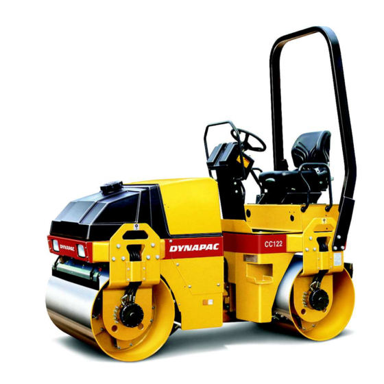
Hide thumbs
Also See for CC102:
- Maintenance manual (36 pages) ,
- Workshop (41 pages) ,
- Diagrams (38 pages)

Subscribe to Our Youtube Channel
Related Manuals for Dynapac CC102


Summary of Contents for Dynapac CC102
- Page 1 DYNAPAC CC102/102C, CC122/122C CC132, CC142/142C OPERATION O102EN3 Box 504, SE-371 23 Karlskrona, Sweden Phone: +46 455 30 60 00, Fax: +46 455 30 60 30 www.dynapac.com...
- Page 2 ILF015WO1...
- Page 3 Vibratory roller CC102/102C, CC122/122C CC132, CC142/142C Operation O102EN3, December 2001 Diesel engine: CC 102/C/122/C/132 Deutz F2L 1011F, Isuzu 3 LD1PW-05 CC 132/142/C Deutz F3L 1011F These instructions apply from: CC 102/C/122/C Deutz PIN (S/N) *60110102* Isuzu (-II) PIN (S/N) *60220102*...
- Page 4 CONTENTS Page Safety instructions (Also read the safety manual) ... 3 Safety when driving ............4, 5 Safety decals, location and description ......6, 7 Machine and engine plates ..........8 Instruments and controls ..........9 Instruments and controls, functional description ..10, 11 Instruments and controls in cab ........
-
Page 5: Safety Instructions (Also Read The Safety Manual)
17. Make no changes or modifications on the roller that could affect safety. Changes may only be made following written consent by Dynapac. 18. Do not use the roller until the hydraulic fluid has reached its normal working temperature. -
Page 6: Safety When Driving
SAFETY WHEN DRIVING Driving near an edge When driving near an edge, at least two thirds of the drum width must be on solid ground. Remember that the machine’s center of gravity is displaced outwards when stee- ring to one side. For example, it moves to the right when steering to the left. -
Page 7: Safety When Driving
SAFETY WHEN DRIVING Sitting position Always remain seated in the operator’s seat for all driving. If the operator rises from his seat the horn will sound, or on some versions the brakes will be applied. Always fasten the seat belt if the machine is equipped with one. -
Page 8: Safety Decals, Location And Description
SAFETY DECALS, LOCATION AND DESCRIPTION (The figure shows the Combo version) CC 102/C/122/C/132/142/C O102EN3... -
Page 9: Safety Decals, Location And Description
SAFETY DECALS, LOCATION AND DESCRIPTION 903459 903422 991658 Crush zone, articulation/ The operator is urgently Diesel fuel drum. Maintain a safe requested to read the safety distance from the crush manual, and the operation zone. and maintenance instructions, before using the machine. -
Page 10: Machine And Engine Plates
MACHINE AND ENGINE PLATES Machine plate The machine type plate (1) is affixed on the front left side of the frame, by the steering joint. The plate shows the manufacturer’s name and address, type of machine, PIN (product identification number/serial number), weight in working order, engine power and year of manufacture. -
Page 11: Instruments And Controls
INSTRUMENTS AND CONTROLS Fig. 7 Operator’s station 1. Horn 13. Driving lights 2. Ignition switch 14. Sprinkler rubber wheel (Combo)/ 3. Manual/Automatic sprinkler vibration front/rear drum 4. Starter button 15. Hazard flashers 16. Direction indicator 5. Manual/Automatic vibration 6. Reserve/parking brake 17. -
Page 12: Instruments And Controls, Functional Description
INSTRUMENTS AND CONTROLS, FUNCTIONAL DESCRIPTION Items Designation Symbol Function in fig. 7 Horn, switch Press to sound the horn. Main power switch In position O the electric circuit is broken. In position I all electric switches and lamps except the starter motor circuit are powered. Sprinkler system, drum Regulates the flow of water to the drum. -
Page 13: Instruments And Controls, Functional Description
INSTRUMENTS AND CONTROLS, FUNCTIONAL DESCRIPTION Hazard flasher, Turn right to switch on the flashing switch (optional) warning lights. Direction indicator, Turn left to switch on the left direction switch (optional) indicator. The flashing indicator is OFF in the middle position. Pocket for manuals Pull up and open the top of the compartment for access to handbooks. -
Page 14: Instruments And Controls In Cab
INSTRUMENTS AND CONTROLS IN CAB 3 4 5 6 7 8 9 10 11 Fig. 8 Cab 1. Heater control 5. Rear wiper 9. Hazard beacon 2. Fuse boxes 6. Front washer 10. Fan 3. Working lights 7. Rear washer 11. -
Page 15: Before Starting
BEFORE STARTING Battery disconnecter – Switching on Remember to perform daily service. See the operation manual. The battery disconnecter is located in the engine compartment. Turn the key (1) to the ON position. The entire roller is now powered. Item (2) is the engine hour meter. The number of hours is counted as long as the engine is running. - Page 16 BEFORE STARTING Operator’s seat – Setting 1. Set the operator’s seat in a comfortable position and so that the controls are easily accessible. 2. The seat has the following adjustment capabilities: – Length adjustment (1) – Backrest slope (2) – Weight adjustment (3) Always ensure that the seat is secure before beginning operation.
-
Page 17: Before Starting
BEFORE STARTING Instruments and lamps – Check Turn the ignition switch (2) to the right position. 8 9 10 Check that the warning lamps 8, 9 and 10 light. Turn the switches (3) and (14) for sprinklers to opera- ting mode and make sure that the system is working. Fig. -
Page 18: Starting
STARTING Starting the engine Set the forward/reverse lever (21) in neutral. The engine cannot be started if the lever is in any other position. On certain versions, the F/R lever is located at the side of the instrument panel, but the function is the same. Fig. -
Page 19: Operation
OPERATION Driving the roller Under no circumstances may the machine be operated from the outside. The operator must remain seated inside the machine during all operation. Turn the rev control (19) and latch it in its working mode. Check that the steering is working by turning the steering wheel once to the right and once to the left, while the roller is stationary. -
Page 20: Operation/Vibration
OPERATION/VIBRATION Manual/Automatic vibration Select manual or automatic switching ON/OFF with switch (5). In manual mode, the operator must activate vibration via the switch (20) on the forward/reverse lever. In automatic mode, the vibration is activated when the pre-set speed is reached. Even switching off is automatic when the lowest speed is reached. -
Page 21: Braking
BRAKING Using the reserve brake Braking is normally done with the forward/reverse lever. The hydrostatic transmission brakes the roller when the lever is moved toward neutral. In addition, each drum motor has a disc brake that acts as a reserve brake when driving, and as a parking brake when stationary. -
Page 22: Braking
BRAKING Switching off Check instruments and warning lamps to see if any faults are indicated, switch off all lights and other electrical functions. Turn the starter switch (2) to mode O. Lower the instru- ment cover (on rollers without cab) and lock it. Fig. -
Page 23: Parking
PARKING Chocking the drum Never leave the roller with the engine running without first pressing the reserve/ parking brake knob. Make sure that the roller is parked in a safe place for traffic. Chock the drum and wheels if the roller is parked on sloping ground. -
Page 24: Instructions For Lifting
INSTRUCTIONS FOR LIFTING Locking the articulation joint Before lifting the roller, the articulation must be locked to prevent inadvertent turning. Turn the steering wheel so that the machine is set for driving straight forward. Push the reserve/parking brake knob. Then pull down the bright galvanized locking bar (1) from its holder (3), and insert it from below into the hole in the lower articulation mount, push the bar through until its upper end is visible in the hole of the upper... -
Page 25: Instructions For Towing
INSTRUCTIONS FOR TOWING Disengaging the brakes (Optional) The following instructions apply to the CC 102/ 102C, CC 122/122C and also the CC 142C rear wheel motors. Press the reserve/parking brake knob and stop the engine. Chock the drum so the roller does not begin to move on disengaging the brakes. -
Page 26: Instructions For Towing
INSTRUCTIONS FOR TOWING Disengaging the brakes The following instructions apply to the CC 132, CC 142 and CC 142C drums. Press the reserve/parking brake knob and stop the engine. Chock the drum so the roller does not begin to move on disengaging the brakes. The disc brake in each drive motor must be disengaged mechanically, according to the following instructions, before the roller can be... -
Page 27: Towing/Salvaging
TOWING/SALVAGING Towing a roller The roller must be counter-braked when towing; use a towbar because the roller will have no braking ability. The roller must be towed slowly (max. 3 km/h / 1.8 mph) and only a short distance (max. 300 m /275 yds). -
Page 28: Transportation
TRANSPORTATION Roller prepared for transportation Interlock the articulation before hoisting and transportation; follow the instructions under the respective heading. Chock the drums (1) and secure the chocks to the transport vehicle. Block up under the drum frame (2), to avoid overload on the rubber suspension of the drum when lashing. -
Page 29: Operating Instructions – Summary
OPERATING INSTRUCTIONS – SUMMARY 1. Follow the SAFETY INSTRUCTIONS in the Safety Manual. 2. Make sure that all instructions in the MAINTENANCE MANUAL are followed. 3. Turn the battery disconnecter to ON. 4. Put the forward/reverse lever in NEUTRAL. 5. Set the vibration selector for Manual/Automatic to position 0. 6.
Need help?
Do you have a question about the CC102 and is the answer not in the manual?
Questions and answers