
Related Manuals for Dynapac CA 251


Summary of Contents for Dynapac CA 251
- Page 1 DYNAPAC CA 251 OPERATION O251-1EN1 Box 504, SE-371 23 Karlskrona, Sweden Telephone +46 455 30 60 00 Telefax +46 455 30 60 30...
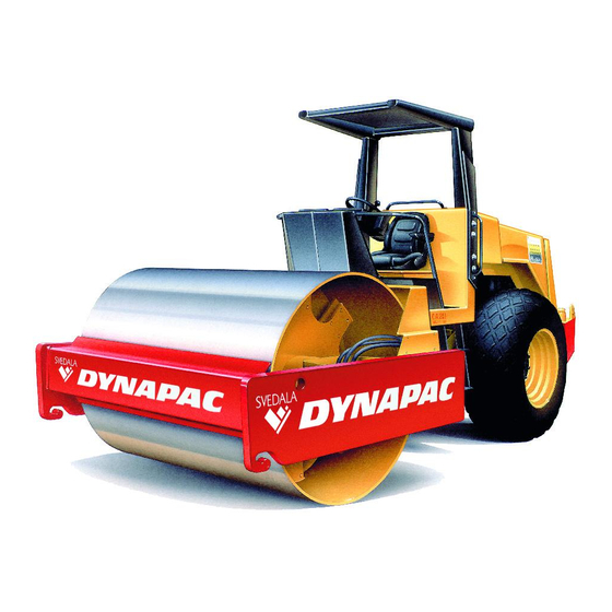
- Page 3 CA 251A PIN (S/N) *58313688* The CA 25-family consists of rollers CA 251, Std, D, PD and CA 251A. These rollers are designed for the compaction of roads, airfields, dams and similar constructions. The CA 251A compacts asphalt, roller concrete, base courses and sub-base courses efficiently and with high capacity.
-
Page 4: Table Of Contents
This manual contains instructions concerning operation and use of the roller. For information regarding care and Diesel engine exhaust and some of its maintenance, see the manual, “MAINTENANCE, CA 251”. constituents are known to the State When starting up and driving a cold machi-... -
Page 5: Safety Instructions
Changes may only be made following written consent by Svedala Dynapac. 18. Do not use the roller until the hydraulic fluid has reached its normal working temperature. Braking distance can be longer than usual if the fluid is cold. See starting instructions in the OPERATION MANUAL. CA 251 O251-1EN1... -
Page 6: Safety Decals, Location And Description
ALWAYS PRESS THE EMERGENCY STOP BUTTON BEFORE LEAVING THE OPERATOR’S PLATFORM WHEN THE ENGINE IS RUNNING Hydraulic fluid (The figure shows accessories.) Crush zone, articulation. Lifting point Lifting point Maintain a safe distance from the crush zone. CA 251 O251-1EN1... -
Page 7: Safety Decals, Location And Description
Warning for rotating engine components. Keep your hands The surface must not be touched. at a safe distance from the danger zone. Diesel fuel Handbooks Crush zone, articulation. Lifting point Lifting point Maintain a safe distance from the crush zone. CA 251 O251-1EN1... -
Page 8: Machine And Engine Plates
This engine conforms to 1999 U.S. EPA and California regulations for heavy duty non-road compression ignition diesel cycle engines as applicable. THIS ENGINE IS CERTIFIED TO OPERATE ON DIESEL FUEL 3935108 Fig. 3 Engine 1. Type plate 2. EPA sign (USA) CA 251 O251-1EN1... - Page 9 34 Handbook compartment 12 Warning lamp – 23 Vibration ON/OFF 35 Lever – Strike-off blade engine oil pressure 24 Forward/reverse lever Up/Down * 13 Voltmeter 25 Speed limiting device * 14 Fuel gauge 26 Speed selector * Optional equipment CA 251 O251-1EN1...
-
Page 10: Instruments And Controls, Functional Description
Fuel gauge Indicates level of the fuel tank. Indicates temperature of the hydraulic fluid. Temperature gauge Normal temperature range 65°C–80°C hydraulic fluid (149°F–176°F). Stop the engine if the meter indicates more than 85°C (185°F) and remedy the cause. CA 251 O251-1EN1... - Page 11 Working speed (Low) In the MAN mode the vibration is switched Vibration setting ON/OFF with (23). (optional equipment) Vibration is OFF in the O mode. The AUT mode gives automatic switching of vibration ON/OFF while driving forward or reverse. CA 251 O251-1EN1...
- Page 12 Manuals for safety, operating and maintenance Handbook compartment that are not to be removed from the machine. Regulates movement of the strike-off blade Lever, strike-off blade Up/Down. Move the lever down to lower, UP/Down and up to raise the blade. (optional equipment) CA 251 O251-1EN1...
-
Page 13: Instruments And Controls In Cab
Press to switch on the front working lights. switch Wiper, front, Press to operate the front screen wiper. switch Screenwash front, Press to operate the front screenwash. switch Ventilation fan, Press to start the cab ventilation fan. switch CA 251 O251-1EN1... - Page 14 Lumbar support (4) • Seat slope (5) • Fig. 8 Operator’s seat 1. Lever - length adjustment 2. Lever - back slope 3. Lever - weight adjustment 4. Knob - lumbar adjustment 5. Knob - seat slope CA 251 O251-1EN1...
-
Page 15: Before Starting
11. Parking brake knob Field of view Before starting, make sure that the field of view is unobstructed, both in front and behind. All cab windows must be clean and rearview mirrors properly adjusted. Abb. 11 Field of view CA 251 O251-1EN1... - Page 16 Always ensure that the strike-off blade is secured by the locking pin (1) when dri- ving with the blade in its raised position. Always lower the blade to the ground before leaving/parking the roller. Fig. 12b Strike-off blade 1. Locking pin CA 251 O251-1EN1...
-
Page 17: Starting
Ensure that ventilation (extraction) is adequate if the engine is run indoors. (Risk of carbon monoxide poisoning). Fig. 13b Instrument panel 24. Forward/reverse lever 27. Amplitude selector CA 251 O251-1EN1... -
Page 18: Operation
If the air cleaner warning lamp (18) should 16. Engine temperature light while driving and at full engine revs then 18 Warning lamp - air cleaner the main filter is to be cleaned or replaced, see maintenance instructions. CA 251 O251-1EN1... -
Page 19: Operation
Move the lever forward to lower, and backward to raise the blade. Lower the blade before leaving/parking the machine. When driving with the blade raised it must always be secured with the safety pin. Fig. 17 Instrument panel 35. Lever, strike-off blade CA 251 O251-1EN1... -
Page 20: Vibrating/Driving
Instead, drive up and Max. 20° down on sloping ground. The machine or 36% will topple on side slopes greater than 20° or 36%, to the right or left. Fig. 20 Tipping angle on side slopes CA 251 O251-1EN1... -
Page 21: Braking/Stopping
(accessory on rollers without cab) 32. Revs control and lock it. When starting up and driving a cold mach- ine, which implies cold hydraulic fluid, the braking distance will be longer than nor- mal until the machine reaches normal working temperature. CA 251 O251-1EN1... -
Page 22: Parking
The brake warning lamp (10) should then light. Fig. 25 Left instrument panel 10. Brake warning lamp 11. Reserve brake knob CA 251 O251-1EN1... -
Page 23: Hoisting
Check weight of the machine by reading the data punched on the hoisting plate (1). Remember to restore the articulation interlock to its open mode before driving again. Fig. 28 Left side of articulation 1. Articulation lock in open mode CA 251 O251-1EN1... -
Page 24: Towing
Remember to re-tighten the brake valve. Unscrew the adjusting screw (4) to its initial position 34 mm (1.34 Fig. 30 Rear axle 3. Lock nut in) from the contact surface, and tighten the lock nut 4. Adjusting screw (3). CA 251 O251-1EN1... -
Page 25: Transportation
1 2 3 4 interlock to its open mode before driving 1 2 3 4 1 2 3 4 1 2 3 4 the roller again. Fig. 33 Transportation 1. Chock 2. Block up 3. Lashing wire CA 251 O251-1EN1... -
Page 26: Operating Instructions - Summary
- Grip the steering wheel firmly. - Be prepared for a sudden stop. Parking: - Stop the engine and chock the drum and wheels. Towing: - See the operation manual. Lifting: - See the operation manual. Transport: - See the operation manual. CA 251 O251-1EN1...
Need help?
Do you have a question about the CA 251 and is the answer not in the manual?
Questions and answers