
Related Manuals for RKI Instruments 72-6ABL-C


Summary of Contents for RKI Instruments 72-6ABL-C
- Page 1 GX-6000 Operator’s Manual Part Number: 71-0362 Revision: L Released: 6/27/19 www.rkiinstruments.com...
- Page 2 WARNING Read and understand this instruction manual before operating instrument. Improper use of the gas monitor could result in bodily harm or death. Periodic calibration and maintenance of the gas monitor is essential for proper operation and correct readings. Please calibrate and maintain this instrument regularly! Frequency of calibration depends upon the type of use you have and the sensor types.
-
Page 3: Table Of Contents
Table of Contents Chapter 1: Introduction ......... . . 10 Overview . - Page 4 Measuring Mode, Normal Operation ........35 Monitoring an Area .
- Page 5 Chapter 5: User Mode ..........92 Overview.
- Page 6 Updating the Auto Zero Setting (AUTO ZERO) ......149 Updating the Demand Zero Setting (DEMAND ZERO) ......149 Zero Follower Setting (ZERO FOLLOWER) .
- Page 7 Bar Hole Testing ............178 Performing a Bar Hole Test .
- Page 8 Benzene Select Mode ........... 211 Viewing Benzene Select Mode Data.
- Page 9 Not tested in oxygen enriched atmospheres (above 21%). NOTE: RKI Instruments, Inc. recommends that you refer to ISA-RP12.13, Part II-1987 or an equivalent international recommended practice for guidance in the use of combustible gas detection instruments.
-
Page 10: Chapter 1: Introduction
Chapter 1: Introduction Overview This chapter briefly describes the GX-6000 gas monitor. This chapter also describes the GX-6000 Operator’s Manual (this document). Table 1 at the end of this chapter lists the specifications for the GX-6000. About the GX-6000 Using an advanced detection system consisting of up to six gas sensors, the GX-6000 sample draw gas monitor is capable of detecting the presence of combustible gas, oxygen ), carbon monoxide (CO), hydrogen sulfide (H S), and various other toxic gases... - Page 11 WARNING: The Model GX-6000 detects oxygen deficiency, elevated levels of oxygen, combustible gases, carbon monoxide, and hydrogen sulfide, all of which can be dangerous or life threatening. When using the GX-6000, you must follow the instructions and warnings in this manual to assure proper and safe operation of the unit and to minimize the risk of personal injury.
-
Page 12: Specifications
Specifications Table 1: Standard Sensor Specifications/Alarm Points Combustible Oxygen (O Hydrogen Carbon VOCs, Isobutylene Calibration Gas, Methane Sulfide Monoxide Standard** (CO) Low Range PID High Range PID Calibration Standard** Detection 0 - 100 %LEL 0 - 40 0 - 100.0 0 - 500 0 - 50000 ppb 0 - 6000 ppm... - Page 13 Indication Combustible Gas (LEL), Catalytic Type Sensor Accuracy ° • -10°C to 40 C: 5% of full scale ° • -20°C to 50 C: 6% of full scale Oxygen • ± 0.5% O Hydrogen Sulfide • ± 5% of reading or ± 2 ppm H S (whichever is greater) Carbon Monoxide •...
-
Page 14: About This Manual
Dimensions Approximately 200(H) x 68(W) x 52(D) mm (7.9”H x 2.7”W x 2.0”D) and Weight Approximately 400 g (14 oz.) About this Manual Although the GX-6000 can support up to 6 sensors, this manual specifically describes an instrument with the four standard sensors and a PID sensor. See the appendices for descriptions of other sensors. -
Page 15: Chapter 2: Description
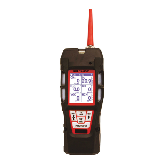
Chapter 2: Description Overview This chapter describes the GX-6000 instrument and accessories. Instrument Description The GX-6000 includes the case, LCD, control buttons, flashlight LED, alarm LEDs, infrared communication port, buzzer, vibrator, printed circuit board, pump, flow chamber, sensors, filters, inlet filter holder, and batteries. Inlet Filter Flashlight LED Holder... -
Page 16: Control Buttons
Control Buttons Five control buttons are located below the LCD. They are, from left to right and top to bottom, DISP/LOCK, AIR, SHIFT (PANIC), POWER/ENTER, and RESET. Table 3: GX-6000 Control Button Functions Button Function(s) DISP/LOCK • activates Display Mode •... -
Page 17: Vibrator
adjustment options. Vibrator A vibrating motor inside the GX-6000 case vibrates for gas alarms, unit malfunctions, and as an indicator during normal use of the various modes of the GX-6000. Printed Circuit Boards (PCBs) The GX-6000 printed circuit boards analyze, record, control, store, and display the information collected. -
Page 18: Filters
Regardless of the calibration gas, the PID channel will still detect and respond to a variety of volatile organic compounds (VOCs). Consult RKI Instruments, Inc. for other available PID configurations and to specify the desired PID configuration when a unit is ordered. -
Page 19: Inlet Filter Holder
The lithium ion battery pack can be recharged by placing the GX-6000 in its battery charging station or by placing the battery pack in the charging station. NOTE: Use of batteries or battery chargers not specified by RKI Instruments, Inc. will compromise the CSA classification and may void the warranty. See “Replacing or Recharging the Batteries”... -
Page 20: Included Accessories
Included Accessories Included accessories consist of the tapered rubber nozzle, belt clip, rubber boot, wrist strap, and the sample hose/probe. Tapered Rubber Nozzle A cone shaped 4 inch long rubber nozzle is included with the GX-6000 as standard. It can be installed on the inlet fitting by pushing the larger end over it. -
Page 21: Screen Protector
Screen Protector The clear screen protector can be installed over the GX-6000’s LCD to prevent it from getting scratched. Remove the GX-6000’s rubber boot. Orient the GX-6000 so that the LCD is as horizontal as possible. Clean the LCD with rubbing alcohol. Place 1 drop of water in the center of the LCD. -
Page 22: External Dilution Fitting
The filter comes with a tubing stub and plug on each end. Both plugs must be removed before using the filter and must be reinstalled for storage. The filter does not have a preferred flow direction. When used with a CO scrubber, the VOC zero filter gets connected to the instrument and the CO scrubber gets connected to the VOC zero filter. - Page 23 Use #10 screws to mount the DIN rail to the wall. Install the charger(s) on the DIN rail. Seat the top of the DIN rail in the top slot on the back of the charger. Press the bottom of the charger toward the DIN rail until it locks into place.
- Page 24 Figure 8: 1-Charger Installation Figure 9: 4-Charger Installation To remove any charger(s) from the DIN rail: a. Remove the clamps by pushing on the bottom of the clamp and pulling on the top of the clamp. b. Slide the charger(s) off the DIN rail. Figure 10: Charger Removal 24 •...
-
Page 25: Chapter 3: Operation
Chapter 3: Operation Overview This chapter explains how to use the GX-6000 to perform confined space entry monitoring or general area monitoring in Normal Mode. There are three operational modes in Normal Mode: Measuring Mode, Display Mode, and Calibration Mode. While in Normal Mode, the unit is normally operating in Measuring Mode. - Page 26 If LUNCH BREAK is turned on (see “Updating the Lunch Break Setting (LUNCH BREAK)” on page 149), the Lunch Break Screen appears. The unit counts down from 5 seconds at the top of the screen. 4:07 LUNCH BREAK 5 SEC YES:ENTER NO:DISP •...
- Page 27 instructions to calibrate the GX-6000. When you are done with the calibration and exit Calibration Mode, the unit will begin the startup sequence. If the calibration was successful, the screen above will not appear again until the unit is due for calibration. If the calibration was not successful, the screen above will again appear in the startup sequence.
- Page 28 • If the unit is due for calibration and CAL EXPRD is set to NO EFFECT, then the following alert screen displays and the buzzer sounds in a double pulsing pattern. 4:07 CAL DATE PAST NO EFFECT CAL MODE : ENTER If you want to enter Calibration Mode, press and release the POWER/ENTER button.
- Page 29 NOTE: If BUMP DISP is set to OFF, the bump test menu item will not appear in Calibration Mode even though the instrument is prompting you to perform a bump test. A bump test can always be performed in Maintenance Mode, if necessary.
- Page 30 • If the unit is due for bump testing and BUMP EXPRD is set to NO EFFECT, then the following alert screen displays and the buzzer sounds in a double pulsing pattern. 4:07 BUMP DATE PAST NO EFFECT CAL MODE : ENTER If you want to enter Calibration Mode, press and release the POWER/ENTER button.
- Page 31 The Battery Voltage Screen appears for a few seconds. 4:07 BATTERY VOLTAGE 4.5V BATTERY TYPE ALKALINE LATCHING The Active Gases Screen appears for a few seconds indicating which channels are active and their target gas. SMART 1 Isobutylene %LEL 10.6 eV GX-6000 Operator’s Manual Chapter 3: Operation •...
- Page 32 The full scale values and the gas alarm setpoints are displayed by five screens in sequence: the Full Scale Screen, the Low Alarm Screen, High Alarm Screen, STEL Alarm Screen, and TWA Alarm Screen. Each screen remains on the LCD for three seconds.
- Page 33 11 . If the GX-6000 experiences a sensor failure during start up, a screen indicating which sensor failed appears and the buzzer sounds a double pulsing tone once per second. In the example below, the CH sensor has failed. SENSOR FAIL %LEL If you wish to continue, press and release the RESET button to acknowledge the...
-
Page 34: Performing A Demand Zero
Performing a Demand Zero Before using the GX-6000, it is recommended to set the fresh air readings for the target gases by performing a demand zero. This will set the CH S, CO, and PID channels to zero and the OXY channel to 20.9%. Find a fresh-air environment. -
Page 35: Measuring Mode, Normal Operation
GX-6000. The maximum sample hose length recommended for the GX-6000 is 50 feet. Consult RKI Instruments, Inc. for longer sample hose lengths. If a gas alarm occurs, take appropriate action. See “Responding to Alarms” on page 43. -
Page 36: Using Optional Sample Hoses
Sample hose lengths of more than 50 feet are not recommended for the GX- 6000 because of flow rate reduction and increased response time. Consult RKI Instruments, Inc. for hose lengths longer than 50 feet. The chart below illustrates how response time is affected by the sample hose length. - Page 37 Table 5: LEL Hydrocarbon Conversions LEL Conversion Factor LEL Conversion Factor Cal.) Cal.) Acetone 1.79 Iso Butane 1.47 Acetylene 1.92 2.27 Benzene 2.00 Methane 1.00 Ethane 1.09 Methanol 1.92 Ethanol 2.50 Pentane 1.56 Ethylene 1.06 Propane 1.35 Heptane 2.50 Propylene 1.32 Hexane 2.08...
-
Page 38: Voc Detection
VOC Detection When monitoring for VOCs using the PID sensor, keep the following in mind: • Regardless of what gas the PID sensor is calibrated to (factory calibration is to isobutylene), the PID sensor will still detect and respond to a variety of volatile organic compounds (VOCs). -
Page 39: Snap Log Mode
Snap Log Mode The snap logging function in Snap Log Mode allows the user to record data at a specific time and have it saved to the data logger. The data is assigned a snap log ID and is saved with the station ID that was in use when the data was taken. - Page 40 You can change the Station ID to be used with the snap log by pressing the SHIFT (PANIC) button and then pressing the DISP/LOCK button. The Station ID Select Screen will appear and the current Station ID will be flashing. 4:07 STATION ID VALVE 3...
-
Page 41: Measuring Mode, Alarms
Measuring Mode, Alarms This section covers alarm indications in Measuring Mode. It also describes how to reset the GX-6000 after an alarm has occurred and how to respond to an alarm condition. NOTE: False alarms may be caused by radio frequency (RF) or electromagnetic (EMI) interference. - Page 42 Table 6: Alarm Types and Indications Alarm Type Visual Indications Other Indications Low Flow • The display indicates FAIL LOW Double pulsing tone once FLOW per second • Alarm LED arrays flash once per second • Backlight turns on Low Battery Warning •...
-
Page 43: Responding To Alarms
Table 6: Alarm Types and Indications Alarm Type Visual Indications Other Indications Panic • Screen unaffected for 5 seconds • Single pulsing tone before alarm starts twice per second for 5 User presses and holds the seconds before alarm • MAN DOWN flashes at top of SHIFT (PANIC) button. - Page 44 If the sensor failure continues, replace the sensor as described in “Replacing a Sensor” on page 113. If the sensor failure condition continues after you have replaced the sensor, contact RKI Instruments, Inc. for further instructions. 44 • Chapter 3: Operation GX-6000 Operator’s Manual...
- Page 45 Attempt to change the date using the DATE menu item in Maintenance Mode. See “Setting the Date and Time (DATE)” on page 137. If the date cannot be set correctly, contact RKI Instruments, Inc. as soon as possible. Responding to System Failure Alarms...
-
Page 46: Display Mode
CAUTION: There will be no datalogging function if you operate the instrument after a 022 system failure. Contact RKI Instruments, Inc. as soon as possible. Responding to a Man Down Warning 1 and Warning 2 The Man Down Warning 1 and Warning 2 alarms occur after the WARNING 1 TIME and WARNING 2 TIME, respectively, has passed since the last movement of the instrument. -
Page 47: Tips For Using Display Mode
Table 9: Display Mode Items Menu Item (page number) Description DATE AND BATTERY (pg.54) View the date/time, battery voltage, and battery type LOG REMAIN (pg.55) View the log time remaining LOG CLEAR (pg.55) Clear the log data PUMP OFF (pg.57) Turn the pump on or off (if the PUMP OFF DISP item in Maintenance Mode is set to ON) USER ID (pg.58) -
Page 48: Pid Gas Name Screen
PID Gas Name Screen The standard PID channel is configured for and calibrated to isobutylene. If calibration to a different gas is required for an application, the PID channel can also be configured for other gases. Regardless of what gas the PID sensor is configured for and calibrated to, the sensor will still detect and respond to a variety of volatile organic compounds (VOCs). - Page 49 Use the AIR and SHIFT (PANIC) buttons to scroll through the letter and list options. To view the gas names behind a letter, User List, or Recent List, press and release the POWER/ENTER button when the cursor is next to the desired letter. DISP I s o b u t a n o l I s o b u t y l a c e t a t...
-
Page 50: Peak Screen
Peak Screen The peak screen displays the highest (lowest for oxygen) concentrations detected since the GX-6000 was turned on. Peak readings are stored in the GX-6000’s memory until a higher level is detected (lower for oxygen), the peak reading is cleared, or the GX-6000 is turned off. -
Page 51: Stel Screen
STEL Screen The STEL Screen displays the short term exposure limit (STEL) readings for H S, CO, and high range VOC only. The STEL reading is the average reading over the last 15 minutes. STEL 10.0 TWA Screen The TWA Screen displays the time weighted average (TWA) readings for H S, CO, and high range VOC only. -
Page 52: View Alarm Settings Screen
View Alarm Settings Screen The View Alarm Settings Screen gives you the option to view the gas alarm settings for all active channels. DISP ALARM POINTS YES :ENTER NO :DISP EXIT :RESET To view the gas alarm settings, do the following: With the View Alarm Settings Screen displayed, press and release the POWER/ ENTER button. - Page 53 F.S. 40.0 %LEL 100.0 6000 19.5 %LEL SHIFT (PANIC) 40.0 400.0 STEL 23.5 %LEL 30.0 60.0 1000 Pressing and releasing the POWER/ENTER button while in a settings screen will cause the instrument to simulate that condition. The buzzer, LED’s, and vibration will activate.
-
Page 54: Time In Operation Screen
Time in Operation Screen The Time In Operation Screen displays the length of time since the GX-6000 was turned on if the lunch break feature is turned off. With LUNCH BREAK set to OFF, the time in operation is reset when the GX-6000 is turned off. See “Updating the Lunch Break Setting (LUNCH BREAK)”... -
Page 55: Log Time Remaining Screen
Log Time Remaining Screen The Data Logging screen displays the time remaining until the data logger memory is full. DISP LOG REMAIN 129 HOUR LOG CLEAR Screen CAUTION: Once you clear the data logger, you cannot retrieve any data previously stored in the data logger. - Page 56 To clear the data logger memory, do the following: With the LOG CLEAR Screen displayed, press and release the POWER/ENTER button. The following screen appears asking you to confirm that you want to clear the data logger memory. DISP LOG CLEAR YES : ENTER NO : DISP CONFIRM ?
-
Page 57: Pump Off Screen
Pump Off Screen WARNING: The GX-6000 is not a gas monitoring device while the pump is off. NOTE: The item appears in Display Mode only if the PUMP OFF DISP menu item in Maintenance Mode is turned ON. The factory setting for PUMP OFF DISP is OFF. -
Page 58: Select User Id Screen
Select User ID Screen This screen only appears in Display Mode if the ID DISPLAY item in Maintenance Mode is set to ON. Use this screen to select a user ID from the user ID list in the GX-6000’s memory. The current user ID is displayed. A user ID can be up to 16 characters long. The GX-6000 can store up to 128 user IDs. -
Page 59: Select Station Id Screen
When the desired user ID is displayed, press and release the POWER/ENTER button. NOTE: To exit the selection screen without saving a change, press and release the DISP/LOCK button. You will return to the Select User ID screen without saving the user ID change. The unit will save the selected user ID as the current one and will return you to the Select User ID Screen. - Page 60 To select a different station ID: With the Select Station ID Screen displayed, press and release the POWER/ENTER button. The current user ID will be displayed and it will be flashing. DISP STATION ID TANK 5 Use the AIR and SHIFT (PANIC) buttons to scroll through the available station IDs.
-
Page 61: Viewing Snap Logger Data
Viewing Snap Logger Data The Snap Logging Screen allows you to view data from previous snap logs. For information on how to use the snap logging feature, see “Snap Log Mode” on page 39. DISP REC. DATA DISP YES :ENTER NO :DISP EXIT :RESET With the snap logging screen displayed, press and release the POWER/ENTER... -
Page 62: Peak Bar Screen
To view the data in a snap log ID, press and release the POWER/ENTER button. REC DATA 20.9 %LEL The gas readings that were taken during the snap log are displayed. You can use the AIR and SHIFT (PANIC) buttons to scroll through the different snap logs. The gas readings will change as you view different snap log data but the snap log ID is not visible from this screen. -
Page 63: Gas Display Screen
Gas Display Screen The Gas Display Screen allows the user to choose how the gas readings are displayed in Measuring Mode. A description of the choices can be found in Table 10 below. If anything other than DISPLAY ALL is selected, the instrument will return to DISPLAY ALL when it is turned off and turned back on. -
Page 64: Lcd Flip Screen
Press and release the POWER/ENTER button to return to the Gas Display Screen. To return to the Gas Display Screen without saving any changes, press and release the DISP/LOCK button. LCD Flip Screen If INVERT SELECT is set to ON, the instrument’s LCD will automatically flip if the instrument is turned upside down. -
Page 65: Combustible Sensor Protection Screen
Combustible Sensor Protection Screen If combustible gas levels greater than 100 %LEL are expected, the catalytic LEL sensor can be disabled to protect it. If the catalytic LEL sensor is disabled, there will be no %LEL alarms in Measuring Mode. DISP CAT (LEL) SENSOR PROTECTION... -
Page 66: Lcd Background Color Flip Screen
LCD Background Color Flip With LCD BACKGROUND set to ON, the LCD colors will flip. The background will be black instead of white and the text will be white instead of black. With LCD BACKGROUND set to OFF (factory setting), the LCD background will be white and the LCD text will be black. -
Page 67: Data Logging
To change the language back to English, do the following: With the Language Screen showing, press and release the POWER/ENTER button. The following screen will appear asking you to confirm that you want to change the language back to English. DISP LANGUAGE CHANGE... - Page 68 Table 11: Data Logging Capacity Interval Data Logging Time Time 10 seconds 10 hours 20 seconds 20 hours 30 seconds 30 hours 1 minute 60 hours 3 minutes 180 hours 5 minutes 300 hours 10 minutes 600 hours For a complete description of the Data Logger Management Program and procedures for downloading data to a computer, see the GX-6000 Data Logger Management Program Operator’s Manual.
-
Page 69: Chapter 4: Calibration Mode
Chapter 4: Calibration Mode Overview This section describes the GX-6000 in Calibration Mode. In Calibration Mode, you can move through a menu of screens to do the following: • Perform a fresh air (zero) adjustment • Perform a span adjustment on all channels simultaneously using auto calibration •... -
Page 70: Calibration Supplies And Equipment
10% - 16% oxygen. • A demand-flow regulator to provide adequate sample gas flow NOTE: RKI Instruments, Inc. recommends that you dedicate a regulator for use with chlorine (Cl ) gas and that you do not use that dedicated regulator for any other gases, particularly hydrogen sulfide (H •... -
Page 71: Calibrating Using The Auto Calibration Method
/CO/H S/isobutylene is a proprietary gas mix developed by RKI Instruments, Inc. for calibrating a PID sensor in the presence of the other gases during an auto calibration. It can also be used for a single calibration of a PID sensor. Do not use a similar gas mix provided by any other manufacturer when calibrating a PID channel. - Page 72 If the unit prompts you for the password, enter it by using the AIR and SHIFT (PANIC) buttons to select each password number and then pressing and releasing POWER/ENTER to enter the number and move on to the next one. NOTE: You will only be prompted to enter a password if the PASSWORD menu item in User Mode is set to ON.
- Page 73 To continue with the fresh air adjustment, press and hold the AIR button. If you do not want to continue, press and release the DISP/LOCK button and the unit will return to the Calibration Mode Screen. The GX-6000 will indicate that it is adjusting the zero reading for a few seconds and then it will prompt you to release the AIR button.
-
Page 74: Performing A Span Adjustment
Performing a Span Adjustment Install the demand flow regulator onto the 4-gas or 5-gas calibration cylinder. Connect the sample tubing to the demand flow regulator. Install the sample hose and probe on the GX-6000 inlet fitting. Make sure the probe’s two halves are tightened firmly together to avoid leaks that can affect the calibration. - Page 75 To check or update the gas concentrations, use the AIR and SHIFT (PANIC) buttons to put the cursor next to CONCENTRATION and press and release the POWER/ENTER button to display the Calibration Gas Values Screen. AUTO CONCENTRATION 50 %LEL 12.0 25.0 ppm 50 ppm 100 ppm...
- Page 76 12 . When you are done adjusting the calibration gas values, move the cursor to ESCAPE. AUTO CONCENTRATION 50 %LEL 12.0 25.0 ppm 50 ppm 100 ppm ESCAPE 13 . Press and release the POWER/ENTER button. The instrument returns to the Auto Cal Menu.
- Page 77 15 . Press and release the POWER/ENTER button. The first of the Gas Select Screens, the standard four sensors screen, will be displayed. In addition to the standard four sensors screen, there is a separate screen for each installed smart sensor, and an ESCAPE screen that will take you back to the Auto Cal menu.
- Page 78 17 . Connect the tubing from the demand flow regulator to the rigid tube on the probe. Allow the GX-6000 to draw gas for one minute. 18 . Press and release the POWER/ENTER button to set the span adjustment for each channel to the programmed values.
- Page 79 22 . If you are using a 5-gas calibration cylinder: a. Leave the tubing connected to the rigid tube on the probe. Continue with Step 23. 23 . Use the AIR and SHIFT (PANIC) buttons to move the cursor next to GAS SELECT.
- Page 80 25 . With the VOC channel’s Gas Select Screen displayed, press and release the POWER/ ENTER button. The target gas selection screen will display. This screen allows you to select the gas you want to use for calibration. Isobutylene will always be displayed on the top line.
-
Page 81: Returning To Measuring Mode
29 . If you are using a 5-gas calibration cylinder: a. Since calibration gas has already been flowing to the PID sensor while the other channels were being calibrated, the PID sensor reading should be stable and ready for adjustment. b. -
Page 82: Calibrating Using The Single Calibration Method
Calibrating Using the Single Calibration Method Single Calibration allows you to calibrate one channel at a time. This is useful if you only want to calibrate one or two channels. Setting the Fresh Air Reading While in the Calibration Mode Screen, move the cursor to the AIR CAL menu item by using the SHIFT (PANIC) button. -
Page 83: Performing A Span Adjustment In Single Calibration
c. Let the instrument draw through the VOC zero filter for 1 minute before continuing. To continue with the fresh air adjustment, press and hold the AIR button. If you do not want to continue, press and release the DISP/LOCK button and the unit will return to the Calibration Mode Screen. - Page 84 Move the cursor next to the SINGLE CAL menu item by using the AIR or SHIFT (PANIC) button. CAL MODE AIR CAL AUTO CAL SINGLE CAL NORMAL MODE Press and release the POWER/ENTER button. The Select Sensor Screen appears. SINGLE SINGLE CAL ESCAPE Move the cursor next to the sensor you want to calibrate with the...
- Page 85 Press and release the POWER/ENTER button. The target gas selection screen will display. This screen allows you to select the gas you want to use for calibration. Isobutylene will always be displayed on the top line. The second line will show the gas that is currently selected in the PID Gas Name Screen in Display Mode.
- Page 86 13 . Press and release the POWER/ENTER button to save the span value. The LCD will indicate that the calibration has ended, then the Select Sensor Screen appears. SINGLE SINGLE SINGLE CAL PASS ESCAPE 14 . Disconnect the tubing from the GX-6000’s probe. 15 .
-
Page 87: Performing A Bump Test
Performing a Bump Test NOTE: The BUMP DISP menu item in Maintenance Mode is factory set to OFF. The BUMP TEST menu item will not appear unless BUMP DISP is set to ON. See “Updating the Bump Display Setting (BUMP DISP)” on page 141 for instructions. - Page 88 Move the cursor next to the BUMP TEST menu item by using the SHIFT (PANIC) button. CAL MODE AIR CAL AUTO CAL SINGLE CAL BUMP TEST NORMAL MODE Press and release the POWER/ENTER button. The first of the Gas Select Screens, the standard four sensors screen, will be displayed.
- Page 89 10 . With the desired sensor screen displayed, connect the tubing from the demand flow regulator to the rigid tube on the probe then quickly press and release the POWER/ ENTER button to proceed to the Bump In Progress Screen. The instrument will count down.
- Page 90 12 . When AUTO CAL in the BUMP PARAMETERS menu item in Maintenance Mode is set to ON: If all channels pass the bump test: a. The results screen appears. You can scroll between the bump test results and the bump test gas readings with the AIR and SHIFT (PANIC) buttons.
- Page 91 b. At the end of the calibration, the instrument displays the results from both the bump test and the calibration. Use the AIR and SHIFT (PANIC) button to scroll between the calibration/bump test results, the bump test gas readings, and the calibration gas readings.
-
Page 92: Chapter 5: User Mode
Chapter 5: User Mode Overview This section describes the GX-6000 in User Mode. See Table 12 below for a list of the items found in User Mode, the page that the menu item’s instructions can be found on, and a short description of the menu item. Table 12: User Mode Menu Items Menu Item (page number) Description... - Page 93 The screen that appears will depend on the setting of User Mode’s PASSWORD item. If PASSWORD is set to OFF (factory setting), continue with Step 4. If PASSWORD is set to ON, continue with Step 6. PASSWORD PASSWORD MODE SELECT USER MODE INPUT MAINTENANCE...
-
Page 94: Setting The Date And Time
Setting the Date and Time NOTE: The example screen shown below assumes a DATE FORMAT setting of MM/ DD/YYYY (factory setting). If your instrument’s DATE FORMAT is set to something else, your screen will appear different. From the main menu, place the cursor next to DATE. Press and release POWER/ENTER. -
Page 95: Configuring The Channels
Configuring the Channels The CONFIGURE CH menu item allows you to rearrange the display order of the active channels. From the main menu, place the cursor next to CONFIGURE CH. Press and release POWER/ENTER. The Configure Channels screen appears with the cursor next to CH1. - Page 96 AIR and SHIFT (PANIC) to move the cursor next to the desired configuration for the selected channel. In the example below, the cursor has been moved next to the H2S (H2S ) selection. USER CHANNEL 1 CH4 (HC ) O2 (OX ) H2S (H2S ) CO (CO ) VOC (SM1)
-
Page 97: Updating The Language Setting
Updating the Language Setting The LANGUAGE menu item allows you to select the language for the GX-6000’s user interface. The available choices are English (factory setting), Japanese, Italian, Spanish, German, French, Portuguese, Russian, and Korean. USER LANGUAGE ENGLISH JAPANESE ITALIAN SPANISH GERMAN FRENCH... -
Page 98: Turning The Password Function On Or Off
The first line displays the ROM number. The ROM number indicates the firmware version number. In the above example, the ROM number is 05017. The bottom line displays the firmware file’s checksum, 62C7 in the above example. Press and release the POWER/ENTER button again to return to the main menu. Turning the Password Function On or Off With PASSWORD set to ON, the GX-6000 prompts you for a password when you enter User Mode and Calibration Mode. -
Page 99: Exiting User Mode
Repeat Step 6 and Step 7 to select the remaining numbers. When you press and release POWER/ENTER to enter the last number, the password is saved and you return to the main menu. Exiting User Mode From the main menu, place the cursor in front of START MEASURE at the bottom of the menu. -
Page 100: Chapter 6: Maintenance
WARNING: RKI Instruments, Inc. recommends that service, calibration, and repair of RKI Instruments be performed by personnel properly trained for this work. Replacing sensors and other parts with original equipment does not affect the intrinsic safety of the instrument. - Page 101 • The sensor for the affected channel(s) may need replacement. • Heart symbol at the • A microprocessor error has • Contact RKI Instruments, Inc. for top of the screen occurred. further instruction. becomes steadily on or disappears •...
-
Page 102: Replacing Or Recharging The Batteries
Replacing Alkaline Batteries NOTE: Use Procell PC 1500 alkaline batteries or RKI Instruments, Inc. lithium-ion battery pack 49-1619 to maintain the CSA classification of the GX-6000. Use of other batteries will void the CSA classification and may void the warranty. - Page 103 Grasp the end of the battery cover that’s closest to the bottom of the instrument and lift it up. Figure 12: Opening Battery Cover Carefully remove the old alkaline batteries. Verify that the battery compartment and electrical contacts are clean. Carefully install the new AA alkaline batteries according to the battery diagram inside the battery compartment.
-
Page 104: Replacing The Lithium Ion Battery Pack
Replacing the Lithium Ion Battery Pack NOTE: Use Procell PC 1500 alkaline batteries or RKI Instruments, Inc. lithium-ion battery pack 49-1619 to maintain the CSA classification of the GX-6000. Use of other batteries will void the CSA classification and may void the warranty. -
Page 105: Recharging The Lithium Ion Battery Pack
Install a new battery pack. If the battery pack release latch moved back into its closed position, slide the latch to the right with one hand and insert a new battery pack with the other. 1. Be Sure Battery Pack Release Push New Battery Pack Down Latch is Pushed to the Right Figure 15: Installing the Battery Pack... - Page 106 If using an AC powered charging station, plug the AC adapter into an electrical outlet. AC Power Supply Power Supply Jack (on bottom of charger) DC12V To AC Outlet AC Powered Charging Station Figure 16: Connecting the Charging Station’s AC Adapter If using a DC powered charging station, plug the 12 VDC vehicle plug adapter into a vehicle’s 12 VDC power socket.
-
Page 107: Recharging The Lithium Ion Battery Pack Out Of The Instrument
Place the GX-6000 into the battery charging station as shown in Figure 18 below so that the metal contacts on the back of the unit come into contact with the metal contacts on the back of the holder in the charging station. When proper contact has been made, the red LED on the charging station will turn on. - Page 108 Make sure the GX-6000 is off. Confirm that the power adapter’s DC output cord is plugged into the charger. If using an AC powered charging station, plug the AC adapter into an electrical outlet. AC Power Supply Power Supply Jack (on bottom of charger) DC12V...
- Page 109 The construction of the charging stations allows them to be chained together but a separate adapter must be used for each charging station. One adapter will not operate more than one charging station. If necessary, remove the battery pack from the instrument as described in Step 1 - Step 6 in “Replacing the Lithium Ion Battery Pack”...
-
Page 110: Replacing The Probe's Particle Filter And Hydrophobic Filter Disk
Replacing the Probe’s Particle Filter and Hydrophobic Filter Disk Inspect the probe’s internal components if you notice that the GX-6000’s pump sounds bogged down or if an unexplained low flow alarm occurs. Replace the particle filter and hydrophobic filter disk if they appear dirty or saturated with liquid. Replace the gasket in the probe if it appears damaged. -
Page 111: Replacing The H S Scrubber Disk And The Charcoal Filter
Remove the white hydrophobic filter disk from the top of the bottom half. The disk sits in a black gasket. Place the new filter disk flat on top of the gasket. Make sure that it sits in the gasket and does not extend over the gasket’s edge. Set the new particle filter on top of the filter disk. - Page 112 To replace the charcoal filter, pull the old one out of its recess in the sensor gasket if it did not already come out and replace it with a new one. You do not have to remove the sensor gasket to do this. The charcoal filter sits in a recess on top of it. H2S Scrubber Disk Charcoal Filter Sensor G asket...
-
Page 113: Replacing A Sensor
Insert the flow chamber back into the instrument. Tighten the flow chamber’s four screws that were loosened in Step 2. To verify that the sensor gasket was inserted properly: a. Turn the GX-6000 on. b. Plug the inlet with your finger. c. - Page 114 LEL Sensor Smart Sensor 1 CO Sensor Position H2S Sensor Smart Sensor 2 Position Oxygen Sensor H 2 S Figure 25: Replacing a Sensor CAUTION: When replacing a sensor, verify that the sensor is properly aligned with its socket before inserting it into the socket. The CO and H S sensors have alignment slots which match up with alignment tabs in the sockets.
- Page 115 Place the sensor gasket and filters back over the sensors ensuring that the sensor gasket seals with the sensors and the flow fittings. The flow fitting connections need to be facing up and cannot be skewed sideways. The gasket must be pushed down in the center and secured under the gasket aligning tabs.
-
Page 116: Replacing The Hydrophobic Filter And Wire Mesh Disk
Replacing the Hydrophobic Filter and Wire Mesh Disk Verify that the GX-6000 is off. Locate the clear plastic filter holder at the top of the GX-6000. Grasp the filter holder and turn it 1/4 turn counterclockwise. 4. Pull the filter holder away from the case. The wire mesh disk and hydrophobic filter are located in the case and are retained by a rubber gasket. -
Page 117: Pid Sensor Maintenance
Reinstall the filter holder. Align the two wide tabs on the bottom of the filter holder with the two wide slots in the case where the filter holder fits. Push the filter holder into the case and turn it 1/4 turn clockwise until it snaps into place. PID Sensor Maintenance The PID sensor includes user serviceable parts. - Page 118 Hold the PID sensor steady on the working surface with one hand and using the other hand, locate the tabs on the electrode stack removal tool and insert them into the slots on the side of the PID sensor near the face. Figure 28: Using Removal Tool Squeeze the removal tool to push the tabs into the sensor slots until the electrode stack and lamp are released.
- Page 119 14 . Use this cotton swab to polish the PID lamp window. Use a circular motion, applying light pressure to clean the lamp window. Do not touch the lamp window with your fingers. Figure 30: Polishing the Electrode Lamp Window 15 .
- Page 120 19 . Twisting the lamp slightly during insertion will help to ensure the lamp window is snug against the stack's front electrode. The lamp should be supported by the O-ring. 20 . Continuing to hold the electrode stack between your forefinger and thumb, carefully insert the lamp into the lamp cavity in the sensor ensuring that the lamp remains in position.
-
Page 121: Replacing The Pid Sensor's Lamp
29 . To verify that the sensor gasket was inserted properly: a. Plug the inlet with your finger. b. Verify that the GX-6000 goes into low flow alarm. If the GX-6000 does not go into low flow alarm, turn the instrument off and attempt to seat the sensor gasket again. - Page 122 Hold the PID sensor steady on the working surface with one hand and using the other hand, locate the tabs on the electrode stack removal tool and insert them into the slots on the side of the PID sensor near the face. Figure 33: Using Removal Tool Squeeze the removal tool to push the tabs into the sensor slots until the electrode stack and lamp are released.
- Page 123 13 . Hold the electrode stack between the thumb and forefinger of one hand and place the window end of the new lamp inside the O-ring seal in the electrode stack with the other hand as shown below. Take care not to touch the lamp window. Figure 34: Reinstalling the Electrode Lamp 14 .
- Page 124 20 . Place the sensor gasket and filters back over the sensors ensuring that it seals with the sensors and the flow fittings. The flow fitting connections need to be facing up and cannot be skewed sideways. The gasket must be pushed down in the center and secured under the gasket aligning tabs.
-
Page 125: Replacing The Pid Sensor's Electrode Stack
Replacing the PID Sensor’s Electrode Stack The electrode stack can last for the life of the PID sensor if the GX-6000 is used in a very clean, controlled environment. When used in a heavily contaminated or dirty environment, the electrode stack may only last a month. A contaminated electrode stack will cause a drop in sensitivity which can cause problems calibrating the PID channel. - Page 126 Squeeze the removal tool to push the tabs into the sensor slots until the electrode stack and lamp are released. 10 . Carefully lift the PID sensor body away from the electrode stack and lamp. If the lamp remains lodged in the sensor body, carefully remove it with tweezers. 11 .
- Page 127 20 . Place the sensor gasket and filters back over the sensors ensuring that it seals with the sensors and the flow fittings. The flow fitting connections need to be facing up and cannot be skewed sideways. The gasket must be pushed down in the center and secured under the gasket aligning tabs.
-
Page 128: Chapter 7: General Parts List
Chapter 7: General Parts List Table 16 lists part numbers for the GX-6000’s replacement parts and accessories. Table 16: General Parts List Part Number Description 06-1248RK-03 Calibration kit tubing, 3 foot length 10-1093RK Screw, for flow chamber 13-0112RK Wrist strap 13-0123 Belt clip 13-6022... - Page 129 Table 16: General Parts List (cont.) Part Number Description 49-1120RK AA size alkaline battery 49-1619 Li-ion battery pack 49-1620 Alkaline battery pack 49-2182-01 Battery charger, BC-6000, with 100 - 240 VAC adapter 49-2183 Battery charger, BC-6000, with 12 VDC adapter 51-1500RK PID sensor replacement lamp, 0 - 50,000 ppb, for PID-001 sensor 51-1502...
- Page 130 Table 16: General Parts List (cont.) Part Number Description 81-1055RK Regulator, demand-flow type (for 17- and 34-liter steel cylinder) 81-6AAX-DLV Calibration kit: 34 liter four-gas (CH S/CO) cylinder, 34 liter 10 ppm IBL in air cylinder, demand flow regulator, calibration tubing 81-6ABI-DLV Calibration kit: 34 liter five-gas (IBL/CH S/CO) cylinder, 34 liter 5 ppm SO...
-
Page 131: Appendix A: Maintenance Mode
Appendix A: Maintenance Mode Overview This appendix describes the GX-6000 in Maintenance Mode. The GX-6000 is factory-set to suit most applications. Update settings in Maintenance Mode only if required for your specific application. Maintenance Mode items and their factory settings are listed in Table 17 below. - Page 132 Table 17: Maintenance Mode Menu Items Menu Item (Page # of Description) Choices or Action Factory Setting BUMP BUMP ESCAPE return to BUMP SETTING PARAMETERS PARAMETERS menu (cont’d) (cont’d) BUMP REMINDER (pg.143) • ON • OFF BUMP INTERVAL (pg.143) 0-30 DAYS 30 DAYS BUMP EXPRD (pg.144) •...
- Page 133 Table 17: Maintenance Mode Menu Items Menu Item (Page # of Description) Choices or Action Factory Setting ZERO FOLLOWER (pg.150) For each channel: • ON • OFF ZERO SUPPRESS (pg.150) 0 - 3% of full scale 2% of full scale* IR AUTO RANGE (pg.150) •...
-
Page 134: Entering Maintenance Mode
Table 17: Maintenance Mode Menu Items Menu Item (Page # of Description) Choices or Action Factory Setting LOG SETTING LOG INTERVAL (pg.155) • 10 SEC 300 SEC (pg.155) • 20 SEC • 30 SEC • 60 SEC • 120 SEC •... - Page 135 The screen that appears will depend on the setting of User Mode’s PASSWORD item. If User Mode’s PASSWORD is set to OFF (factory setting), continue with Step 4. If User Mode’s PASSWORD is set to ON, continue with Step 6. PASSWORD 4:07 PASSWORD...
- Page 136 If Maintenance Mode’s PASSWORD is set to ON (factory setting), enter the password by using the AIR and SHIFT (PANIC) buttons to select each password number and then pressing and releasing the POWER/ENTER button to enter it and move on to the next number until all of the numbers are entered. The password is 0006.
-
Page 137: Using Maintenance Mode
Tips for Using Maintenance Mode • When in the main menu, the cursor (>) indicates which menu item will be selected if the POWER/ENTER button is pressed and released. • Use the SHIFT (PANIC) button to move the cursor down through the main menu and submenu items, and to lower values or change the setting in a specific option. -
Page 138: Performing A Calibration (Gas Calibration)
AIR or SHIFT (PANIC) to display the desired setting. Press and release POWER/ENTER to save the setting and return to the main menu. Performing a Calibration (GAS CALIBRATION) From the main menu, place the cursor next to GAS CALIBRATION. Press and release POWER/ENTER. The Gas Calibration Screen appears. MAINTE GAS CALIBRATION AIR CAL... -
Page 139: Updating Calibration Settings (Cal Setting)
Updating Calibration Settings (CAL SETTING) The CAL SETTING menu item in Maintenance Mode has a sub menu with 5 menu items: CAL REMINDER, CAL INTERVAL, CAL EXPRD, CAL CHECK GAS, and ESCAPE. MAINTE CAL SETTING CAL REMINDER CAL INTERVAL CAL EXPRD CAL CHECK GAS ESCAPE From the main menu, place the cursor next to CAL SETTING. - Page 140 Updating the Calibration Expired Setting (CAL EXPRD) This item defines what indication is given during start up when calibration is due and CAL REMINDER is set to ON. With CAL EXPRD set to CONFIRM TO USE (factory setting), the GX-6000 will give an indication at start up if calibration is past due and will require the user to decide whether to perform a calibration or continue and use the GX-6000 without calibrating.
-
Page 141: Updating Bump Test Settings (Bump Setting)
Updating Bump Test Settings (BUMP SETTING) The BUMP SETTING menu item in Maintenance Mode has a sub menu with 7 menu items: BUMP DISP, BUMP PARAMETERS, BUMP REMINDER, BUMP INTERVAL, BUMP EXPRD, BUMP CHECK GAS, and ESCAPE. MAINTE BUMP SETTING BUMP DISP BUMP PARAMETERS BUMP REMINDER... - Page 142 Updating the Bump Parameters (BUMP PARAMETERS) The BUMP PARAMETERS menu item in the Bump Test Settings sub-menu has its own sub-menu with 5 menu items: GAS TIME, CHECK, CAL TIME, AUTO CAL, and ESCAPE. MAINTE BUMP PARAMETERS GAS TIME CHECK CAL TIME AUTO CAL ESCAPE...
- Page 143 Press and release POWER/ENTER. The current Cal Time value will begin to flash. AIR or SHIFT (PANIC) to display the desired setting. Press and release POWER/ENTER to save the setting. The value will stop flashing. Updating the AUTO CAL Setting With AUTO CAL set to ON (factory setting), if a bump test fails, the unit will automatically begin a calibration.
- Page 144 Updating the Bump Expired Setting (BUMP EXPRD) This item defines what indication is given during start up when a bump test is due and BUMP REMINDER is set to ON. With BUMP EXPRD set to CONFIRM TO USE (factory setting), the GX-6000 will give an indication at start up if a bump test is past due and will require the user to decide whether to perform a bump test or continue and use the GX-6000 without bump testing.
-
Page 145: Updating Alarm Parameters (Alarm Setting)
Returning to the Maintenance Mode Menu (ESCAPE) From the BUMP SETTING screen, place the cursor next to ESCAPE. Press and release POWER/ENTER. The instrument will return to the main menu. Updating Alarm Parameters (ALARM SETTING) The ALARM SETTING menu item in Maintenance Mode has a sub menu with 4 menu items: ALARM POINTS, ALARM LATCHING, ALARM SILENCE, and ESCAPE. - Page 146 Move the cursor next to the channel of the alarm point you want to update. Press and release POWER/ENTER. The channel’s alarm points and alarm operation (oxygen only) are displayed. ALARM - P ALARM - P ALARM - P L - H AL 1 10 %LEL AL 1...
-
Page 147: Turning The Pump On/Off Display On Or Off (Pump Off Disp)
11 . When you are done making changes to all channels, use SHIFT (PANIC) to move the cursor next to ESCAPE. 12 . Press and release POWER/ENTER to return to the ALARM SETTING menu. Updating the Alarm Latching Setting (ALARM LATCHING) With ALARM LATCHING set to LATCHING (factory setting), the GX-6000 remains in alarm condition until the alarm condition passes and the RESET button is pressed. -
Page 148: Turning The User/Station Id Function On Or Off (Id Display)
AIR or SHIFT (PANIC) to display the desired setting. Press and release POWER/ENTER to save the setting and return to the main menu. Turning the User/Station ID Function On or Off (ID DISPLAY) With ID DISPLAY set to ON, the User ID and Station ID Screens display during start up and in Display Mode. -
Page 149: Updating The Lunch Break Setting (Lunch Break)
Updating the Lunch Break Setting (LUNCH BREAK) With LUNCH BREAK set to OFF (factory setting), the GX-6000 automatically starts new TWA and PEAK reading collection and resets the time in operation at startup. With LUNCH BREAK set to ON, the Lunch Break Screen displays during startup. From this screen, you can choose to continue accumulating TWA and PEAK readings and the time in operation from the last time the GX-6000 was used or start collecting new readings and reset the time in operation. -
Page 150: Zero Follower Setting (Zero Follower)
Zero Follower Settings (ZERO FOLLOWER) The ZERO FOLLOWER setting is not intended for field adjustment. The default setting for most target gases is ON. The default setting for carbon dioxide channels and some configurations of non-standard toxic gas channels is OFF. The oxygen channel does not support this feature. -
Page 151: Turning The Key Tone Noise On Or Off (Key Tone)
If you set CONFIRMATION to ON, the interval screen will appear MAINTE CONFIRMATION AIR or SHIFT (PANIC) to display the desired setting. Press and release POWER/ENTER to save the setting and return to the main menu. Turning the Key Tone Noise On or Off (KEY TONE) With KEY TONE set to ON (factory setting), the instrument will beep every time a button is pressed. -
Page 152: Updating The Leak Check/Bar Hole Mode Setting (L./B. Mode)
Updating the Leak Check/Bar Hole Mode Setting (L./B. MODE) With L./B. MODE set to LEAK CHECK MODE/BAR HOLE MODE, the Mode Select Screen appears when the unit is turned on. You are able to select from Normal Mode, Leak Check Mode, and Bar Hole Mode. With L./B. -
Page 153: Updating The Man Down Settings (Man Down)
From the main menu, place the cursor next to CO DISPLAY. Press and release POWER/ENTER. The CO Display Screen appears. AIR or SHIFT (PANIC) to display the desired setting. Press and release POWER/ENTER to save the setting and return to the main menu. Updating the Man Down Settings (MAN DOWN) The MAN DOWN menu item in Maintenance Mode has a sub menu with 6 menu items: MAN DOWN, PANIC, WARNING 1 TIME, WARNING 2 TIME, ALARM TIME,... - Page 154 AIR or SHIFT (PANIC) to display the desired setting. Press and release POWER/ENTER to save the setting and return to the MAN DOWN MENU screen. Updating the WARNING 1 TIME Setting The WARNING 1 TIME is the amount of time that has to pass between a Man Down detection and the first preliminary alarm.
-
Page 155: Updating The Datalogging Parameters (Log Setting)
Updating Datalogging Parameters (LOG SETTING) The LOG SETTING menu item in Maintenance Mode has a sub menu with 4 menu items: LOG INTERVAL, LOG CLEAR DISP, LOG OVER WRITE, and ESCAPE. MAINTE LOG SETTING LOG INTERVAL LOG CLEAR DISP LOG OVER WRITE ESCAPE From the main menu, place the cursor next to LOG SETTING. -
Page 156: Adjusting The Low Flow Setpoint (Flow Adjust)
Press and release POWER/ENTER. The Log Over Write Screen appears. AIR or SHIFT (PANIC) to display the desired setting. Press and release POWER/ENTER to save the setting and return to the LOG SETTING screen. Returning to the Maintenance Mode Menu (ESCAPE) From the LOG SETTING screen, place the cursor next to ESCAPE. -
Page 157: Viewing The Rom/Sum Of The Instrument (Rom/Sum)
Connect a flow meter with a valve to the inlet of the instrument and adjust it to 0.2 LPM ± 0.1 LPM. This will be the low flow setpoint. You do not need to adjust anything at the instrument. Press and release the POWER/ENTER button to save the changes and return to the main menu. -
Page 158: Restoring The Default Settings (Restore Default)
GX-6000 to its original configuration as shipped from the factory. There are some special GX-6000 configurations that may have a different default configuration than the standard. Consult RKI Instruments, Inc. for information regarding non-standard default configurations. WARNING: When the GX-6000 is restored to its default configuration, the zero and span values for each channel are reset. -
Page 159: Exiting Maintenance Mode (Start Measure)
Press and release POWER/ENTER. The Restore All? Screen appears asking if you want to restore the default configuration. MAINTE RESTORE DEFAULT RESTORE ALL ? YES : ENTER NO : DISP If you do not want to restore the default configuration, press and release DISP/LOCK to return to the main menu. -
Page 160: Appendix B: Maintenance Mode 2
Appendix B: Maintenance Mode 2 Overview This appendix describes the GX-6000 in Maintenance Mode 2. The GX-6000 is factory- set to suit most applications. Update settings in Maintenance Mode 2 only if required for your specific application. A description of the Maintenance Mode 2 items is shown in Table 18 below. - Page 161 If User Mode’s PASSWORD has been set to OFF, the Mode Select screen will appear, prompting you to choose the mode you’d like to enter. Use the AIR and SHIFT (PANIC) buttons to put the cursor in front of MAINTENANCE and press and release the POWER/ENTER button. A password screen will appear.
-
Page 162: Tips For Using Maintenance Mode 2
10 . The main menu displays. MAINTE 2 MAINTENANCE 2 GAS COMB HC SELECT START MEASURE 11 . Use the AIR or SHIFT (PANIC) button to move the cursor up and down through the menu items. Tips for Using Maintenance Mode 2 •... -
Page 163: Changing The Catalytic Lel Channel's Target Gas (Hc Select)
Press and release POWER/ENTER. The Gas Combination Screen appears and all channels are displayed. FLASH GAS COMB H2S ON SM1 ON SM2 OFF ESCAPE Move the cursor next to the channel you want to update. Press and release POWER/ ENTER. The channel’s current on/off setting will begin to flash. AIR and SHIFT (PANIC) to change the on/off setting. -
Page 164: Changing The Streaming Setting (Streaming Mode)
Changing the Streaming Setting (STREAMING MODE) With STREAMING MODE set to ON, the GX-6000 streams real-time data from the IrDA port. Contact RKI Instruments, Inc. to obtain document 71-0486 and to get more information about Streaming Mode. With STREAMING MODE set to OFF (factory setting), the GX-6000 does not stream real-time data from the IrDA port. -
Page 165: Appendix C: Using The Gx-6000 In Leak Check Mode
Appendix C: Using the GX-6000 in Leak Check Mode Overview This chapter explains how to operate the GX-6000 in Leak Check Mode. Leak Check Mode is used to pinpoint small leaks of combustible gas from valves, flanges, connections, and other potential leak points. When the GX-6000 is in Leak Check Mode, only the catalytic combustible sensor and potentially the CO sensor, depending on the setting of the CO DISPLAY parameter in Maintenance Mode, will be active. - Page 166 Press and briefly hold down the POWER/ENTER button. Release the button when you hear a beep. The Normal Mode Select Screen displays. 4:07 MODE SELECT NORMAL MODE 100 %LEL 40.0 100.0 6000 Use the AIR or SHIFT (PANIC) button to scroll to the Leak Check Mode Select Screen.
-
Page 167: Performing A Demand Zero, Leak Check Mode
The GX-6000 is now monitoring for gas in Leak Check Mode. The pump is on and one of the following screens appears depending on the setting of the CO DISPLAY parameter in Maintenance Mode. 4:07 4:07 5000 5000 F . S . F . -
Page 168: Setting The Display Range Value
Setting the Display Range Value The GX-6000’s Leak Check Mode has 4 display range ppm values to choose from: 500 ppm, 1000 ppm, 2000 ppm, and 5000 ppm. NOTE: The GX-6000 is always detecting combustible gas up to 5000 ppm. The display range value is only adjusting what part of the detection range is displayed on the LCD. -
Page 169: Overscale Conditions
Overscale Conditions If the gas level goes over the display range, the gas reading will be replaced with “OVER” and the LEDs and buzzer will pulse continuously until the overscale condition has cleared. Once the gas level gets low enough, the instrument will start showing ppm readings again. 4:07 OVER 5000... -
Page 170: Snap Log Mode, Leak Check Mode Operation
Snap Log Mode, Leak Check Mode Operation The snap logging function in Snap Log Mode allows the user to record data at a specific time and have it saved to the data logger. The data is assigned a snap log ID and is saved with the station ID that was selected when the data was taken. - Page 171 To return to the Station ID Select Screen without taking a base reading, press and release the RESET button. To exit Snap Log Mode completely and return to Leak Check Mode, press and release the DISP/LOCK button. In order to get a base, or background, reading, take the instrument a few feet away from where you intend to test.
-
Page 172: Viewing Snap Log Data In Leak Check Mode
11 . The unit will display SAVED before returning to the Station ID Select Screen. 12. Repeat Step 5 through Step 11 to take additional snap log data. 13. To exit Snap Log Mode at any time without taking a snap log or when you are finished recording snap logs, press and release the DISP/LOCK button. - Page 173 ID Screen Data Screen REC DATA 4:07 DATE 1000 5/20/2015 Leak Check POWER/ MM/DD/YYYY Mode Peak PEAK 3:47 Data ENTER 5000 NUMBER F . S . TANK 5 SHIFT SHIFT REC DATA 4:07 DATE 5/20/2015 Leak Check MM/DD/YYYY POWER/ Mode Base BASE 3:45 Data...
-
Page 174: Turning Off The Gx-6000, Leak Check Mode
Snap log data that was taken in Leak Check Mode operation will have 2 sequential screens that are part of one data set. One screen is for the base reading and the other screen is for the peak reading. “BASE” and “PEAK” will appear in the gas reading screen for each type of reading, respectively. -
Page 175: Appendix D: Using The Gx-6000 In Bar Hole Mode
Appendix D: Using the GX-6000 in Bar Hole Mode Overview This chapter explains how to operate the GX-6000 in Bar Hole Mode. Bar Hole Mode is used to perform consistent checks of bar holes when tracking down underground gas leaks. When the GX-6000 is in Bar Hole Mode, only the IR combustible and oxygen (if installed and active) channels are displayed. -
Page 176: Start Up, Bar Hole Mode
Start Up, Bar Hole Mode This section explains how to start up the GX-6000 in Bar Hole Mode and get it ready for operation. Turning On the GX-6000, Bar Hole Mode WARNING: Gas alarms are not active when the GX-6000 is in Bar Hole Mode. CAUTION: If any sensors other than an IR CH /IR HC or oxygen sensor is installed, these sensors will not be active while the GX-6000 is in Bar Hole Mode. -
Page 177: Performing A Fresh Air Adjustment, Bar Hole Mode
With the Bar Hole Mode Select Screen displayed, press and release the POWER/ ENTER button to begin the Bar Hole Mode startup sequence. NOTE: If no button is pressed for 20 seconds, the unit will proceed into whichever mode is displayed. See “Turning On the GX-6000”... -
Page 178: Bar Hole Testing
Press and hold the AIR button. The pump will start and the display will prompt you to hold the AIR button. Continue to hold the AIR button until the display prompts you to release the button. The GX-6000 will set the fresh air reading for the combustible gas and oxygen channels as it counts down from 8. - Page 179 Use the AIR and SHIFT (PANIC) buttons to scroll to the desired station ID and press and release POWER/ENTER. The unit will return to the Bar Hole Measuring Screen. 4:07 %LEL 20.9 VALVE 3 Take the GX-6000 to the bar hole that will be tested. Insert the probe into the bar hole and press and release the POWER/ENTER button.
- Page 180 At the end of the sample period, the pump will shut off and the buzzer will sound, then the peak combustible gas reading and the minimum oxygen reading for the sample period will be displayed. The peak combustible gas reading will also be visually displayed on the graph along the bottom of the screen.
-
Page 181: Turning Off The Gx-6000, Bar Hole Mode
• When the purge is complete, the screen will return to the initial Bar Hole Mode screen. 4:07 %LEL 20.9 VALVE 3 If other bar holes will be tested, proceed to the next bar hole and repeat steps Step 5 - Step 7. -
Page 182: Appendix E: Using The Gx-6000 In Inert Mode
Appendix E: Using the GX-6000 in Inert Mode Inert Mode is used to measure the combustible gas and/or oxygen level in a purged environment. In order for the instrument to operate in Inert Mode, the oxygen alarm must be set to H-HH operation meaning that both alarms are increasing. The oxygen Low Alarm High Alarm points are factory set at 5.0% and 10.0%. -
Page 183: Start Up And Operation
Start Up and Operation Connect the tapered rubber nozzle or the sample hose and probe to the GX-6000’s quick connect inlet fitting. Press and briefly hold down the POWER/ENTER button. Release the button when you hear a beep. The Normal Mode Select Screen displays. Use the AIR or SHIFT (PANIC) button to scroll to the Inert Mode Select Screen. -
Page 184: Appendix F: Ess-03 Toxic Sensors
Appendix F: ESS-03 Toxic Sensors Overview The ESS-03 sensors are used to monitor levels of a variety of toxic gases. This appendix describes the GX-6000’s ESS-03 sensors. It also includes instructions to replace an ESS- 03 sensor. Table 19 below lists the available ESS-03 sensors. Table 19: ESS-03 Sensor Specifications Target Gas Detection... -
Page 185: Interference
Interference Although the GX-6000 can support up to two ESS-03 sensors, many combinations are impractical for various reasons including sensor cross sensitivity to other gases. The table below indicators some of the gases that will cause an increased gas reading for the affected sensor. -
Page 186: Start Up And Normal Operation
Start Up and Normal Operation For instructions to startup and use a GX-6000 that includes an ESS-03 sensor, reference “Start Up” on page 25, “Measuring Mode, Normal Operation” on page 35, and “Measuring Mode, Alarms” on page 41. Follow these instructions keeping the following special considerations in mind: •... - Page 187 NOTE: RKI Instruments, Inc. recommends that you dedicate a regulator for use with chlorine (Cl ) gas and that you do not use that dedicated regulator for any other gases, particularly hydrogen sulfide (H To calibrate the standard 4 sensors and/or the high range PID sensor, follow the instructions outlined in “Calibrating Using the Auto Calibration Method”...
- Page 188 After you have completed Step 30 on page 81, the Auto Cal Menu will be displayed. Continue with Step 4 below. AUTO AUTO CAL CONCENTRATION GAS SELECT ESCAPE If you were using a 5-gas (standard 4-gas + ESS-03) calibration cylinder to calibrate the standard 4 sensors, continue to Step 5.
- Page 189 Press and release the POWER/ENTER button. The first of the Gas Select Screens, the standard four sensors screen, will be displayed. In addition to the standard four sensors screen, there is a separate screen for each installed smart sensor, and an ESCAPE screen that will take you back to the Auto Cal menu.
- Page 190 10 . If you are calibrating an HCN sensor, an Alternative Gas screen will appear. The HCN sensor can be calibrated using HCN or PH . This screen allows you to select which gas you want to use. AUTO ALTERNATIVE GAS ESCAPE 11 .
- Page 191 14 . If you are using a 5-gas (standard 4-gas + ESS-03) calibration cylinder: a. Since calibration gas was flowing to the ESS-03 sensor while the standard 4 channels were being calibrated, the ESS-03 sensor reading should be stable and ready for adjustment.
-
Page 192: Calibrating The Ess-03 Sensor Using Single Calibration
See “Performing a Span Adjustment” on page 74 for instructions to calibrate the ESS-03 using single calibration. NOTE: RKI Instruments, Inc. recommends that you dedicate a regulator for use with chlorine (Cl ) gas and that you do not use that dedicated regulator for any other... - Page 193 smart sensor 1 position and a dummy sensor should be installed in the smart sensor 2 position. See the figure below for the location of the smart sensor 1 and 2 positions. Smart Sensor 1 Position Smart Sensor 2 Position H 2 S Figure 40: Smart Sensor Positions Replacing the SO...
- Page 194 Gently pull up the edges of the sensor gasket to loosen it from its connections. Be sure not to lose any of the filters that are in it. The sensors will be exposed. Remove the SO sensor from its socket. Use tweezers to remove the Teflon filter and H S scrubber from the SO sensor’s...
- Page 195 Flow Fitting Connections Gasket Aligning Tabs Figure 42: Sensor Gasket Seating 14 . Insert the flow chamber back into the instrument. 15 . Tighten the flow chamber’s four screws that were loosened in Step 2. 16 . Start up the GX-6000 by pressing and briefly holding the POWER/ENTER button. 17 .
-
Page 196: Parts List
Parts List Table 23: ESS-03 GX-6000 Parts List Part Number Description 33-0176 Teflon filter for SO sensor (need to replace 33-0176 and 33-7135 at the same time) 33-7135 S scrubber disk for SO sensor (need to replace 33-0176 and 33-7135 at the same time) 33-7135-05 S scrubber disk for SO... - Page 197 Part Number Description ESS-B332-NH3 Ammonia sensor, 0 - 400 ppm ESS-B335-CL2 Chlorine sensor, 0 - 10.0 ppm GX-6000 Operator’s Manual Appendix F: ESS-03 Toxic Sensors • 197...
-
Page 198: Appendix G: Ir Sensors
There are also gases that the methane sensor will not detect or respond to. Lists of the gases falling in each of these respective categories can be found below. Consult RKI Instruments, Inc. for combustible gases not listed below. -
Page 199: Description
• • isobutane • • methanol • propane • styrene • toluene The infrared methane sensor is known to not or to poorly respond to the following combustible gases: • acetylene • benzene • hydrogen Description IR Sensor The IR sensor is a smart sensor that stores sensor parameters including the target gas, detection range, alarm points, and calibration settings in its memory. -
Page 200: Co2 Scrubber
Scrubber A carbon dioxide scrubber is factory-shipped with GX-6000s that have an IR CO sensor installed. The scrubber is for use when setting the carbon dioxide sensor’s zero reading only. A single piece of tubing connects both ends of the scrubber when not in use. To prolong the life of the scrubber, be sure the tubing is connected to both ends of the scrubber while the scrubber is not in use or while it is being stored. -
Page 201: Ir Hc Start Up And Normal Operation
IR HC Start Up and Normal Operation For instructions to startup and use a GX-6000 that includes an infrared hydrocarbon sensor, reference “Start Up” on page 25, “Measuring Mode, Normal Operation” on page 35, and “Measuring Mode, Alarms” on page 41. 0-100 %LEL/2.0-30.0 %vol Autoranging The infrared hydrocarbon sensor can be factory set to detect gas in a 0-100 %LEL configuration or an autoranging configuration. -
Page 202: Ir Co2 Start Up And Normal Operation
IR CO Start Up and Normal Operation For instructions to startup and use a GX-6000 that includes an infrared CO sensor, reference “Start Up” on page 25, “Measuring Mode, Normal Operation” on page 35, and “Measuring Mode, Alarms” on page 41. Follow these instructions keeping the following special considerations in mind: •... - Page 203 Reattach the tubing to the open end of the scrubber. Performing a Demand Zero for Instruments with a Carbon Dioxide Sensor and a PID Sensor If your instrument has both an IR CO sensor and a PID sensor, you will need to use both the carbon dioxide scrubber and the VOC zero filter to perform a demand zero.
-
Page 204: Ir Calibration
IR Calibration See “Calibrating Using the Auto Calibration Method” on page 71 or “Calibrating Using the Single Calibration Method” on page 82 for instructions to perform a calibration. NOTE: If you are using the IR HC or IR CH sensors in their autoranging configuration, be sure to calibrate the range you’d like the most accuracy in (either %LEL or %vol). -
Page 205: Parts List
Smart Sensor 1 Position Smart Sensor 2 Position H 2 S Figure 47: Smart Sensor Positions Parts List Table 27: Infrared Sensors Parts List Part Number Description 33-6015RK scrubber 33-6092 VOC zero filter, charcoal, with tubing stubs and plugs (for instruments that include an IR CO sensor and a PID sensor) 81-0012RK-01... - Page 206 Part Number Description 81-0072RK-01 Calibration cylinder, 2.5 %vol CO in nitrogen, 34 liter 81-0072RK-03 Calibration cylinder, 2.5 %vol CO in nitrogen, 103 liter DES-3311-1 Infrared CO sensor, 0 - 10 %vol DES-3311-2 Infrared HC sensor, 0 - 100 %LEL/2.0 - 30.0 %vol autoranging DES-3311-3 Infrared CH sensor, 0 - 100 %LEL/5.0 - 100 %vol autoranging...
-
Page 207: Appendix H: 10.0 Ev/Benzene Pid Sensor
Mode. Even though the 10.0 eV/benzene sensor can be used for general VOC detection, if your application is for general VOC detection and is not related to monitoring for benzene specifically, RKI Instruments, Inc. recommends that the low range or high range 10.6 eV PID sensor be used instead. -
Page 208: Tube And Tube Holder
Tube and Tube Holder Benzene detection typically requires the use of a filter tube. The filter tube will scrub out most VOCs other than benzene but will not scrub out nitrobenzene, cyclohexane, n- octane, or n-pentane. The filter tube is installed in a tube holder and needs to be replaced regularly. -
Page 209: Start Up
Start Up The instructions for starting up a GX-6000 with a 10.0 eV/benzene PID sensor installed are the same as described in “Start Up” on page 25 with the exception of the screens shown in Step 8. Those screens appear as shown below. SMART 1 Benzene %LEL... -
Page 210: Measuring Mode
• The PID Gas Name Screen operates as described in “PID Gas Name Screen” on page 48 but is factory set up for and calibrated to benzene and appears as shown below. If there are 2 PID sensors installed in your GX-6000, the PID Gas Name Screens will appear in Display Mode in the following order regardless of their position in the flow system: 10.0 eV/benzene, 10.6 eV, 11.7 eV. -
Page 211: Benzene Select Mode
Benzene Select Mode Benzene Select Mode allows the user to monitor for benzene in the 0-50.00 ppm range. Readings taken in Benzene Select Mode are saved to the instrument’s memory. See “Viewing Benzene Select Mode Data” on page 217 for a description of viewing data. NOTE: A PID-003L 10.0 eV/benzene sensor must be installed in order for the Benzene Select Mode screen to appear. - Page 212 The pump will stop and the instrument will prompt you to install the filter tube and tube holder. TUBE INSTALL TUBE AND HOLDER YES :ENTER NO :DISP Be sure a filter tube is installed in the tube holder and then attach the tube holder to the instrument’s inlet fitting.
- Page 213 To cancel the measurement, press and release the RESET button. TUBE 0.00 CANCEL ? YES :ENTER NO :DISP 43SEC • Press the POWER/ENTER button to confirm the measurement cancel. • Press the DISP/LOCK button to return to the measuring screen without canceling the measurement.
- Page 214 11 . To start another measurement, press and release the POWER/ENTER button. WARNING: If you take the GX-6000 to an area that is 10 or 15 degrees different than the previous area, allow the instrument 45 minutes to acclimate before taking any readings. Failure to do so may cause the reading to be inaccurate.
- Page 215 13 . To proceed with taking a STEL measurement, press and release the RESET button. TUBE START STEL MEASUREMENT YES :ENTER NO :DISP a. Press and release the POWER/ENTER button to start a STEL measurement. b. The STEL measurement takes 15 minutes and a countdown displays at the bottom of the screen.
- Page 216 d. At the end of the STEL countdown, the STEL reading displays. TUBE BNZ STEL 0.00 REPEAT ? YES :ENTER NO :DISP e. To repeat the STEL measurement, press and release POWER/ENTER. f. To return to Measuring Mode, press and release the DISP/LOCK button. You will be prompted to remove the tube holder from the instrument’s inlet fitting.
-
Page 217: Viewing Benzene Select Mode Data
Viewing Benzene Select Mode Data Readings taken in Benzene Select Mode are saved to the snap logger. To view Benzene Select Mode readings, do the following: From Measuring Mode, press and release the DISP/LOCK button to enter Display Mode. Continue pressing the DISP/LOCK button until the snap logging screen appears. DISP REC. - Page 218 To view the data in a snap log ID, press and release the POWER/ENTER button. ID Screen Data Screen REC DATA REC DATA DATE 5.30 5/20/2015 Benzene POWER/ MM/DD/YYYY Select Mode 3:47 STEL Data ENTER BENZENE SELECT NUMBER TANK 5 STEL SHIFT SHIFT...
-
Page 219: Calibrating The 10.0 Ev/Benzene Pid Sensor
The instrument saves data from a Benzene Select Mode standard measurement and from a Benzene Select Mode STEL measurement (if performed). Data from a Benzene Select Mode standard measurement will say “BENZENE SELECT” below the reading. Data from a Benzene Select Mode STEL measurement will say “BENZENE SELECT”... -
Page 220: Performing An Auto Cal
Setting the Fresh Air Reading See “Setting the Fresh Air Reading” on page 71 for instructions to set the fresh air reading. Performing an AUTO CAL See “Calibrating Using the Auto Calibration Method” on page 71 for instructions to perform an automatic calibration while keeping the following in mind: •... -
Page 221: Performing A Tube Cal
Failure to do so may cause the calibration to be inaccurate. To calibrate the 10.0 eV/benzene sensor in TUBE CAL, you will need: • A benzene calibration cylinder. RKI Instruments, Inc. recommends a concentration of 5 ppm. • A demand-flow regulator to provide adequate sample gas flow. - Page 222 Automatic TUBE CAL To enter Calibration Mode, while in Measuring Mode, press and hold the SHIFT (PANIC) button, then press the DISP/LOCK button and release both buttons. CAL MODE AIR CAL AUTO CAL SINGLE CAL TUBE CAL CAL CODE NORMAL MODE Use the SHIFT (PANIC) button to scroll to TUBE CAL and then press and release the POWER/ENTER button.
- Page 223 Press and release the POWER/ENTER button to enter the TUBE CAL Auto Calibration Menu. TUBE CAL GAS CALIBRATION CONCENTRATION START CAL ESCAPE To view or change the benzene concentration to be used for the TUBE CAL: a. Use the SHIFT (PANIC) button to place the cursor next to CONCENTRATION.
- Page 224 13 . Press and release the POWER/ENTER button to start a calibration. An automatically-determined, temperature-based countdown is displayed at the bottom of the screen. The number to the left of the countdown (“5” in the example below) is the temperature code. APPLYGAS 0.00 45SEC...
- Page 225 17 . Use the SHIFT (PANIC) button to place the cursor next to ESCAPE, then press and release the POWER/ENTER button. You will be prompted to remove the filter tube and tube holder. TUBE CAL REMOVE HOLDER YES :ENTER NO :DISP 18 .
- Page 226 The pump will stop and the instrument will prompt you to install the filter tube and tube holder. INSTALL TUBE AND HOLDER YES :ENTER NO :DISP Be sure a filter tube is installed in the tube holder and then attach the tube holder to the instrument’s inlet fitting.
- Page 227 11 . An automatically-determined, temperature-based countdown is displayed at the bottom of the screen. The number to the left of the countdown (“5” in the example below) is the temperature code. APPLYGAS 0.00 45SEC 12 . At the end of the countdown, use the AIR or SHIFT (PANIC) button to adjust the reading to match the concentration listed on the calibration cylinder.
-
Page 228: Entering A Cal Code
Entering a CAL CODE NOTE: A PID-003L 10.0 eV/benzene sensor must be installed in order for the CAL CODE menu item to appear in Calibration Mode. NOTE: If you begin to use filter tubes from a new box and if the calibration code shown on the new box is different than the calibration code shown on the old box, you must enter the new calibration code before using the new filter tubes. -
Page 229: Maintenance
“3/4” line (into the side without the text and arrow), the tube needs to be replaced. Even though discoloration can be a measure of when to replace the tube, not all gases cause the filter material to discolor which is why RKI Instruments, Inc. recommends GX-6000 Operator’s Manual... - Page 230 that the tube be replaced before starting a new measurement in Benzene Select Mode. If the tubes are being stored in a refrigerator, take them out of the refrigerator and let them sit overnight before using them. Instructions to Replace Tube Remove the front of the tube holder by pushing on the locking mechanism and pulling the front half away from the back half, shown below.
-
Page 231: Parts List
If you are replacing your old tube with a tube from a new box, compare the calibration code listed on the old box to the calibration code listed on the new box. a. If the calibration codes match, there is no need to do anything else. b. -
Page 232: Appendix I: 11.7 Ev Pid Sensor
The PID-004 11.7 eV PID sensor’s lamp (RKI P/N 51-1504) is susceptible to humidity and its service life is not as long as lamps in other PID sensors sold by RKI Instruments, Inc. For this reason, the PID-004 11.7 eV sensor’s lamp is warranted for 2 months from the date of shipment. -
Page 233: Description
The 11.7 eV PID sensor’s lamp is susceptible to humidity. “Turning Off a GX-6000 with an 11.7 eV PID Sensor” on page 235 outlines RKI Instruments, Inc.’s recommendations for prolonging the life of the sensor’s lamp. -
Page 234: Start Up
Start Up The instructions for starting up a GX-6000 with a 11.7 eV PID sensor installed are the same as described in “Start Up” on page 25 with the following exceptions: • Remove the black cap from the inlet fitting before turning on the instrument. •... -
Page 235: Measuring Mode
Measuring Mode The 11.7 eV PID sensor detects VOCs in the 0-1000 ppm range. In the 0-100 ppm range, the reading increment is 0.1 ppm. In the 100-1000 ppm range, the reading increment is 1 ppm. See “Measuring Mode, Normal Operation” on page 35 for a complete description of Measuring Mode. -
Page 236: Calibrating The 11.7 Ev Pid Sensor
Reconnect the tubing to the open end of the dehumidifier filter to help preserve its life. If the filter begins to appear wet, it needs to be replaced. Calibrating the 11.7 eV PID Sensor Setting the Fresh Air Reading See “Setting the Fresh Air Reading” on page 71 for instructions to set the fresh air reading. -
Page 237: Performing A Single Cal
See “Replacing a Sensor” on page 113 for sensor replacement instructions. Replacing the PID Sensor’s Lamp and Electrode Stack RKI Instruments, Inc. recommends that you replace the electrode stack every time you replace the lamp. However, if you replace only the lamp and notice that the instrument is operating properly, it is not necessary to change the electrode stack. -
Page 238: Cleaning The 11.7 Ev Pid Sensor's Lamp
Cleaning the 11.7 eV PID Sensor’s Lamp Since the life of the 11.7 eV lamp is typically only 3 months, cleaning the lamp is not normally needed. However, if the sensor is exposed to high-molecular-weight VOCs, silicones, or amines, the lamp should be cleaned. See “Cleaning the PID Sensor’s Lamp, 10.0 eV and 10.6 eV Lamps”... -
Page 239: Parts List For 11.7 Ev Pid Instruments
Parts List for 11.7 eV PID Instruments The table below lists spare parts for a 11.7 eV PID instrument. Table 31: Spare Parts List for 11.7 eV PID Instruments Part Number Description 07-0220 Rubber cap, black, for dehumidifier filter and GX-6000 inlet fitting 33-0564 PID sensor electrode stack, 11.7 eV sensor 33-2125-01... -
Page 240: Appendix J: Creating A Pid User List
Appendix J: Creating a PID User List Overview This appendix explains how to set up a User List for the GX-6000’s PID sensor(s). This User List appears in the PID Gas Name Screen in the GX-6000’s Display Mode. The PID User List is not related to the GX-6000’s User ID list. -
Page 241: Editing The User List
Editing the User List There are separate PID User Lists for each PID sensor type (10.6 eV, 10.0 eV, 11.7 eV). Be sure that the selected sensor type is the type you would like to edit. The example below shows the 10.6 eV sensor type selected. Select the Show User List box. - Page 242 To reorder the gases in the PID User List: a. Select a gas in the PID User List. b. Click Up and Down to move the selected gas up or down. The gas order shown in the PID User List is how the gases will appear when you access the User List in the GX-6000’s PID Gas List Screen.
- Page 243 Warranty RKI Instruments, Inc. warrants the GX-6000 sold by us to be free from defects in materials, workmanship, and performance for a period of two years from the date of shipment from RKI Instruments, Inc. This includes the instrument and the original sensors.
Need help?
Do you have a question about the 72-6ABL-C and is the answer not in the manual?
Questions and answers