
Subscribe to Our Youtube Channel
Related Manuals for RKI Instruments AirLink 7032


Summary of Contents for RKI Instruments AirLink 7032
- Page 1 AirLink 7032 Gas Monitor Operator’s Manual Part Number: 71-0560 Revision: P2 Released: 9/26/22 RKI Instruments, Inc. www.rkiinstruments.com...
- Page 2 Product Warranty RKI Instruments, Inc. (Manufacturer) warrants its products to be free of defects in workmanship and materials—under normal use and service—for one year from the date of purchase from the manufacturer or from the product's authorized reseller. The manufacturer is not liable (under this warranty) if its testing and examination disclose that the alleged defect in the product does not exist or was caused by the purchaser's (or any third party's) misuse, neglect, or improper installation, testing or calibrations.
-
Page 3: Table Of Contents
Mounting the AirLink 7032 Gas Monitor........ - Page 4 Register Map............. . 51 4 • AirLink 7032 Gas Monitor Operator’s Manual...
-
Page 5: Chapter 1: Introduction
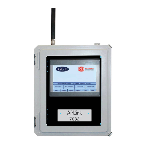
AirLink 7032. About the AirLink 7032 Gas Monitor The AirLink 7032 is a hybrid monitor and data logger that supports either 32 AirLink sensor units or 64 AirLink sensor units depending on the configuration ordered. Either configuration can also be set up for 4, wired 4-20 mA input sensors in place of 4 AirLink sensors. -
Page 6: About This Manual
About this Manual The AirLink 7032 Gas Monitor Operator’s Manual uses the following conventions for notes, cautions, and warnings: NOTE: Describes additional or critical information. CAUTION: Describes potential damage to equipment. WARNING: Describes potential danger that can result in injury or death. -
Page 7: Specifications
Specifications Table 1 lists specifications for the AirLink 7032. Table 1: AirLink 7032 Specifications 120/240V ~ Input Power 22 - 26 V 300 mA max at 24 VDC (monitor without sensor Current Draw assemblies) 3A max (with sensor assemblies) Operating Temperature -20°F to 122°F (-28.9°C to 50°C) - Page 8 Table 1: AirLink 7032 Specifications • Operator’s manual (this document) Standard Accessory • SD card with USB adapter • Strobe Optional Accessories • Horn 8 • Chapter 1: Introduction AirLink 7032 Gas Monitor Operator’s Manual...
-
Page 9: Chapter 2: Internal Components
Chapter 2: Internal Components The inside of the AirLink 7032 contains the terminal board for wiring connections and the AC power supply (for AC versions). The back of the touchscreen module is visible and has an SD card with USB adapter installed on the back for datalogging. - Page 10 Figure 2: Terminal Board 10 • Chapter 2: Internal Components AirLink 7032 Gas Monitor Operator’s Manual...
-
Page 11: Chapter 3: Installation
2. Close and latch the housing door. 3. Prepare the selected mounting site as required to mount the AirLink 7032. It should be mounted at eye level (4 1/2 to 5 feet from the floor). Refer to Figure 3 for the outline and mounting dimensions. - Page 12 Ø .31 x . 19, 4X 29.4 22.2 27.6 20.4 14.4 12.2 Figure 3: Outline and Mounting Dimensions 12 • Chapter 3: Installation AirLink 7032 Gas Monitor Operator’s Manual...
-
Page 13: Wiring The Airlink 7032 Gas Monitor
CAUTION: The internal components can be static sensitive. Use caution when opening the enclosure and handling internal components. WARNING: Make all connections to the AirLink 7032 before you plug in or turn on the AC or DC power source. Before you make any wiring adjustments, always verify that all power sources are not live. - Page 14 Connecting a DC Power Source NOTE: The AirLink 7032 is configured for AC or DC operation, depending on how it is ordered. If you are using AC power as the primary power source, go to the next section, “Connecting an AC Power Source”.
- Page 15 10. Clamp down the enclosure latches. Connecting an AC Power Source NOTE: The AirLink 7032 is configured for AC or DC operation, depending on how it is ordered. If you are using DC power as the primary power source, go to the previous section, “Connecting a DC Power Source”.
- Page 16 • Connect a ground wire from the AC power source to the power supply’s “EG” terminal. NOTE: If the AirLink 7032 was not ordered with any housing holes, at least one hole will have to be drilled to bring in AC power.
- Page 17 7. Connect a black wire from a PLC’s RS-485 B(-) terminal to the terminal labeled “B” on the Modbus Out Terminal Block. Figure 7: Modbus Out Wiring 8. Close the Front Panel. 9. Screw in the thumb-screws. 10. Close the enclosure box. AirLink 7032 Gas Monitor Operator’s Manual Chapter 3: Installation • 17...
- Page 18 4. Locate the Fault Terminal Block on the terminal board. 5. Connect a positive (red) wire to the terminal labeled “+”. 6. Connect a negative (black) wire to the terminal labeled “-”. Figure 8: Fault Indicator Wiring 18 • Chapter 3: Installation AirLink 7032 Gas Monitor Operator’s Manual...
- Page 19 Connecting Sensors The AirLink 7032 allows up to 32 AirLink sensor assemblies or up to 28 AirLink sensor assemblies and 4 wired 4-20 mA type sensor assemblies to be monitored (depending on the configuration ordered). 1. Open the enclosure box to expose the Front Panel.
- Page 20 Relay Wiring The AirLink 7032 has four relays. Each of the four relays may be setup as Normally Open (NO) or Normally Closed (NC). See page 47 for more explanation about relay actuation. NOTE: If installed, the strobe is factory wired to the Relay 1 terminals and the horn is factory wired to the Relay 2 terminals.
- Page 21 Figure 10: Relay Wiring AirLink 7032 Gas Monitor Operator’s Manual Chapter 3: Installation • 21...
-
Page 22: Chapter 4: Startup And Operation
To cycle the Terminal Board power, flip the Power Switch (located on the lower right side of the Terminal Board) to the OFF (and then ON) position. Figure 11: Power Switch Location 22 • Chapter 4: Startup and Operation AirLink 7032 Gas Monitor Operator’s Manual... -
Page 23: Home Screen
Home button. Figure 12: Home Screen After 20 seconds of no button presses in the Home screen, the AirLink 7032 automatically starts scrolling through real-time values for all active channels. Trend Chart Depending on the configuration, the AirLink 7032 can either monitor up to 32 or 64 AirLink sensor assemblies. - Page 24 2. From the Home screen, press and release the Trend Chart button. 3. Select the bank of channels you want to view. 4. Select the full scale range for the chart. 24 • Chapter 4: Startup and Operation AirLink 7032 Gas Monitor Operator’s Manual...
-
Page 25: Real-Time Values
6. Use the buttons at the bottom of the chart to view available data. Real-Time Values Depending on the configuration, the AirLink 7032 can either monitor up to 32 or 64 AirLink sensor assemblies. Alternatively, the AirLink 7032 can monitor 4 wired sensor assemblies with either 28 or 60 AirLink sensor assemblies (depending on the configuration ordered). -
Page 26: View Days Since Last Zero And Cal
View Days Since Last Zero and Cal 1. If necessary, press the Home button to return to the Home screen. 2. From the Home screen, press and release the Real-Time Values button. 26 • Chapter 4: Startup and Operation AirLink 7032 Gas Monitor Operator’s Manual... -
Page 27: Relay Indicators
4. The number of days since the last zero and calibration display for each channel. Alarms Relay indicators appear at the bottom of every screen in the AirLink 7032. The indicators turn either solid red or flash, as described below, to indicate an alarm condition. - Page 28 Gas Alarm The Real-Time Values screen has a column for relay status. If the reading on a particular channel has activated one of the AirLink 7032’s relays, the relay number on that channel’s Real-Time Values screen gets a yellow background.
-
Page 29: Chapter 5: Channel Configuration Menu
NOTE: To save any changes and return to the Home screen at any time, press the Home button. The AirLink 7032 automatically saves any changes and returns to the Home screen 15 minutes after the last button press. -
Page 30: Editing Channel Settings
2. Select the channel bank for the channel you want to set up. 3. Select the channel you want to set up. 4. The channel settings screen appears. AirLink channel Wired channel 30 • Chapter 5: Channel Configuration Menu AirLink 7032 Gas Monitor Operator’s Manual... - Page 31 AirLink: Detector is communicating with the AirLink 7032 on the configuration wirelessly. ordered) Any 4-20 mA type detectors wired directly to the AirLink 7032 must be set up on the following channels: • For 32-channel versions: Channels 29-32 • For 64-channel versions: Channels 61-64 Relay On/Off On: Relay will activate when the selected channels’...
-
Page 32: Changing The Date, Time, And Location
1. Enter the Channel Configuration Menu as described on page 29. 2. Press and release Set Monitor Time Date and Location. 3. Type in the AirLink 7032’s location and the current date and time. 4. Press the Home button to save the settings and return to the Home screen. -
Page 33: Chapter 6: Advanced Configuration Menu
1. Open the enclosure box to expose the Front Panel. 2. Tap the AirLink logo then press and hold the RKI logo for 5 seconds. 3. The base layer of the Advanced Configuration Menu appears. AirLink 7032 Gas Monitor Operator’s Manual Chapter 6: Advanced Configuration Menu • 33... - Page 34 8. Edit the desired parameters. They are described below. Parameter Description Reset AirLink 7032 to Sets the AirLink 7032 back to factory defaults, listed below. Factory Defaults? • Channels 1-28 or 1-60 set to AirLink (depending on the configuration ordered) •...
- Page 35 No: Relay 4 does not act as a fault relay and can be assigned to a gas alarm. 9. After 30 seconds, the AirLink 7032 automatically saves any changes and returns to the Home screen. If you need to change additional settings, repeat Step 2 - Step 8.
-
Page 36: Chapter 7: Maintenance
1. Open the enclosure box to expose the Front Panel. 2. Tap the AirLink logo then press and hold the RKI logo for 5 seconds to enter the Advanced Configuration Menu. 3. Press Enter Calibration Mode. 36 • Chapter 7: Maintenance AirLink 7032 Gas Monitor Operator’s Manual... -
Page 37: Relay Test Mode
Calibration Mode for two hours and then it will start autoscrolling through the Real-Time Values for active channels. 6. Press the Home button to return to the Home screen. NOTE: The AirLink 7032 automatically returns to the Home screen 15 minutes after the last button press. 7. Close the enclosure box. - Page 38 5. 5 seconds after the 4th relay is activated, all relays return to their normal state and Test Relays is no longer selected. 6. Press the Home button to return to the Home screen. NOTE: The AirLink 7032 automatically returns to the Home screen 15 minutes after the last button press. 7. Close the enclosure box.
-
Page 39: Troubleshooting
Table 2 describes symptoms, probable causes, and recommended actions for the most common problems you may encounter with the AirLink 7032. NOTE: This troubleshooting guide describes AirLink 7032 problems only. See the detector head operator’s manuals for preventive maintenance procedures that apply to the detector heads installed on your AirLink 7032. - Page 40 Table 2: Troubleshooting the AirLink 7032 (Continued) Condition Probable Causes Recommended Action • The top card is losing communication to 1. Check the orientation of the the analog sensor board analog sensor board and/or try a new analog sensor board.
- Page 41 Table 2: Troubleshooting the AirLink 7032 (Continued) Condition Probable Causes Recommended Action 1. Since it is 4-20mA, the monitor When using a monitor with a 4-20mA does not know the exact fault (4-20 mA wired connection, F13 may appear when condition.
-
Page 42: Chapter 8: Viewing Usb Log Files
1. Download and install the EZWare-5000 converter software, found here: https://www.maplesystems.com/General/DownloadFile?s=sw&n=EZware- 5000%20v4.65.16&f=ez5000setup.zip 2. Remove the SD card with USB adapter from the AirLink 7032. 3. Plug the SD card with USB adapter into an available port. 4. Use Windows Explorer to view the contents of the SD card. - Page 43 Open Maple Systems\Easy Converter from the Start menu. b. Click the Open button. c. Click Add File. d. Navigate to the .dtl file you want to convert. AirLink 7032 Gas Monitor Operator’s Manual Chapter 8: Viewing Log Files • 43...
- Page 44 Click OK. f. The program indicates that the conversion was successful. 44 • Chapter 8: Viewing Log Files AirLink 7032 Gas Monitor Operator’s Manual...
- Page 45 8. Open converted .xls files in Excel or another spreadsheet software to view the data. 9. Reinstall the SD card with USB adapter into the AirLink 7032’s USB slot. 10. Press Cancel on the message that appears on the display.
-
Page 46: Chapter 9: Parts List
Part No. Description 18-0107RK Conduit hub (3/4 in.) 51-0040-RED Strobe/horn, 20 - 28 VDC, Cl. I Div. 1 Zone 1 71-0560 AirLink 7032 Gas Monitor Operator’s Manual (this document) 46 • Chapter 9: Parts List AirLink 7032 Gas Monitor Operator’s Manual... -
Page 47: Appendix A: Relay Operation
When using a Wet Contact Relay, power should run through the “COMM” terminal to the end equipment. Figure 13: “Dry” Contact Relay Configured as a “Wet” Contact AirLink 7032 Gas Monitor Operator’s Manual Appendix A: Relay Operation • 47... - Page 48 The NC (normally closed) relay contacts are open during non-alarm operation and close when the appropriate alarm condition occurs. Figure 14: Relay Circuit Schematic 48 • Appendix A: Relay Operation AirLink 7032 Gas Monitor Operator’s Manual...
-
Page 49: Appendix B: Introduction To 4-20 Ma Current Loop Signals
4 mA representing the lowest end of the range and 20 mA the highest. The relationship between the current loop and the gas value is linear. In addition, the AirLink 7032 uses values below 4 mA to indicate special status conditions, as shown below:... - Page 50 (DMM), or current meter, may be used in conjunction with the controller and/or to test the 4-20 mA current loop signal. To measure the current, place the meter probes in line with the current loop. 50 • Appendix B: Introduction to 4-20 mA Current AirLink 7032 Gas Monitor Operator’s Manual...
-
Page 51: Appendix C: Rs-485 Modbus Output
The Modbus register maps for 32 and 64-channel versions (applicable to RS-232, RS-485, and USB outputs) of the AirLink 7010 are accessible from the following URLs: • 32-channel version: https://www.rkiinstruments.com/pdf/airlink_7032-32-regmap.pdf • 64-channel version: https://www.rkiinstruments.com/pdf/airlink_7032-64-regmap.pdf AirLink 7032 Gas Monitor Operator’s Manual Appendix C: RS-485 Modbus Output • 51...
Need help?
Do you have a question about the AirLink 7032 and is the answer not in the manual?
Questions and answers