Sign In
Upload
Manuals
Brands
RKI Instruments Manuals
Gas Detectors
72-6ABL-B
RKI Instruments 72-6ABL-B Manuals
Manuals and User Guides for RKI Instruments 72-6ABL-B. We have
1
RKI Instruments 72-6ABL-B manual available for free PDF download: Operator's Manual
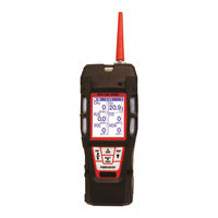
RKI Instruments 72-6ABL-B Operator's Manual (243 pages)
Brand:
RKI Instruments
| Category:
Gas Detectors
| Size: 2 MB
Table of Contents
Table of Contents
3
Chapter 1: Introduction
10
Overview
10
About the GX-6000
10
Specifications
12
About this Manual
14
Chapter 2: Description
15
Overview
15
Instrument Description
15
Case
15
Lcd
15
Control Buttons
16
Flashlight LED
16
Alarm Leds
16
Infrared Communications Port
16
Buzzer
16
Vibrator
17
Printed Circuit Boards (Pcbs)
17
Pump
17
Flow Chamber
17
Sensors
17
Filters
18
Inlet Filter Holder
19
Batteries
19
Included Accessories
20
Tapered Rubber Nozzle
20
Belt Clip
20
Rubber Boot
20
Wrist Strap
20
Sample Hose and Probe
20
Screen Protector
21
Other Accessories
21
VOC Zero Filter
21
External Dilution Fitting
22
DIN Rail Mounting Assembly
22
Chapter 3: Operation
25
Overview
25
Start up
25
Turning on the GX-6000
25
Performing a Demand Zero
34
Turning off the GX-6000
34
Measuring Mode, Normal Operation
35
Monitoring an Area
35
Using Optional Sample Hoses
36
Combustible Gas Detection
36
VOC Detection
38
Oxygen Detection
38
Snap Log Mode
39
Measuring Mode, Alarms
41
Alarm Indications
41
Responding to Alarms
43
Display Mode
46
Tips for Using Display Mode
47
PID Gas Name Screen
48
Peak Screen
50
STEL Screen
51
TWA Screen
51
View Alarm Settings Screen
52
Time in Operation Screen
54
Date/Time, Battery Voltage Screen
54
Log Time Remaining Screen
55
Clear Data Logging Screen
55
Pump off Screen
57
Select User ID Screen
58
Select Station ID Screen
59
Viewing Snap Logger Data
61
Peak Bar Screen
62
Gas Display Screen
63
LCD Flip Screen
64
Combustible Sensor Protection Screen
65
LCD Background Color Flip Screen
66
Language Screen
66
Data Logging
67
Chapter 4: Calibration Mode
69
Overview
69
Calibration Supplies and Equipment
70
Entering Calibration Mode
70
Calibrating Using the Auto Calibration Method
71
Setting the Fresh Air Reading
71
Performing a Span Adjustment
74
Returning to Measuring Mode
81
Calibrating Using the Single Calibration Method
82
Setting the Fresh Air Reading
82
Performing a Span Adjustment in Single Calibration
83
Performing a Bump Test
87
Chapter 5: User Mode
92
Overview
92
Tips for Using User Mode
92
Entering User Mode
92
Setting the Date and Time
94
Setting the Date Format
94
Configuring the Channels
95
Updating the Language Setting
97
Viewing the ROM/SUM of the Instrument
97
Turning the Password Function on or off
98
Exiting User Mode
99
Chapter 6: Maintenance
100
Overview
100
Troubleshooting
100
Replacing or Recharging the Batteries
102
Replacing the Alkaline Batteries
102
Replacing the Lithium Ion Battery Pack
104
Recharging the Lithium Ion Battery Pack
105
Recharging the Lithium Ion Battery Pack out of the Instrument
107
Replacing the Probe's Particle Filter and Hydrophobic Filter Disk
110
Replacing the H S Scrubber Disk and the Charcoal Filter
111
Replacing a Sensor
113
Replacing the Hydrophobic Filter and Wire Mesh Disk
116
PID Sensor Maintenance
117
Cleaning the PID Sensor's Lamp
117
Replacing the PID Sensor's Lamp
121
Replacing the PID Sensor's Electrode Stack
125
Chapter 7: General Parts List
128
Appendix A: Maintenance Mode
131
Overview
131
Entering Maintenance Mode
134
Using Maintenance Mode
137
Setting the Date and Time (DATE)
137
Setting the Date Format (DATE FORMAT)
137
Performing a Calibration (GAS CALIBRATION)
138
Performing a Bump Test (BUMP TEST)
138
Updating Calibration Settings (CAL SETTING)
139
Updating Bump Test Settings (BUMP SETTING)
141
Updating Alarm Parameters (ALARM SETTING)
145
Turning the Pump On/Off Display on or off (PUMP off DISP)
147
Turning the User/Station ID Function on or off (ID DISPLAY)
148
Updating the Backlight Time Setting (BACK LIGHT TIME)
148
Updating the Language Setting (LANGUAGE)
148
Updating the Lunch Break Setting (LUNCH BREAK)
149
Updating the Auto Zero Setting (AUTO ZERO)
149
Updating the Demand Zero Setting (DEMAND ZERO)
149
Zero Follower Setting (ZERO FOLLOWER)
150
Zero Suppression Settings (ZERO SUPPRESS)
150
Updating the Autoranging Setting (IR AUTO RANGE)
150
Updating the Confirmation Alert Setting (CONFIRMATION)
150
Turning the Key Tone Noise on or off (KEY TONE)
151
Turning Inert Mode on or off (INERT MODE)
151
Updating the Leak Check/Bar Hole Mode Setting (L./B. MODE)
152
Setting the Bar Hole Measurement Time (BAR HOLE TIME)
152
Updating the CO Display Setting (CO DISPLAY)
152
Updating the man down Settings (man DOWN)
153
Updating the Datalogging Parameters (LOG SETTING)
155
Adjusting the Low Flow Setpoint (FLOW ADJUST)
156
Viewing the ROM/SUM of the Instrument (ROM/SUM)
157
Turning the Password Function on or off (PASSWORD)
157
Restoring the Default Settings (RESTORE DEFAULT)
158
Exiting Maintenance Mode (START MEASURE)
159
Appendix B: Maintenance Mode 2
160
Overview
160
Entering Maintenance Mode 2
160
Tips for Using Maintenance Mode 2
162
Changing the Gas Combination (GAS COMB)
162
Changing the Catalytic LEL Channel's Target Gas (HC SELECT)
163
Changing the Streaming Setting (STREAMING MODE)
164
Exiting Maintenance Mode 2 (ESCAPE)
164
Appendix C: Using the GX-6000 in Leak Check Mode
165
Overview
165
Start Up, Leak Check Mode
165
Turning on the GX-6000, Leak Check Mode
165
Performing a Demand Zero, Leak Check Mode
167
Leak Testing
167
Setting the Display Range Value
168
Turning the Alarm on and off
168
Locating a Leak
168
Overscale Conditions
169
Peak Hold Mode
169
Snap Log Mode, Leak Check Mode Operation
170
Viewing Snap Log Data in Leak Check Mode
172
Turning off the GX-6000, Leak Check Mode
174
Appendix D: Using the GX-6000 in Bar Hole Mode
175
Overview
175
Start Up, Bar Hole Mode
176
Turning on the GX-6000, Bar Hole Mode
176
Performing a Fresh Air Adjustment, Bar Hole Mode
177
Bar Hole Testing
178
Performing a Bar Hole Test
178
Turning off the GX-6000, Bar Hole Mode
181
Appendix E: Using the GX-6000 in Inert Mode
182
Alarms
182
Start up and Operation
183
Appendix F: ESS-03 Toxic Sensors
184
Overview
184
Description
184
Interference
185
Start up and Normal Operation
186
ESS-03 Calibration
186
Calibrating the ESS-03 Sensor Using Auto Calibration
186
Calibrating the ESS-03 Sensor Using Single Calibration
192
ESS-03 Bump Testing
192
Replacing the ESS-03 Sensor or Changing Sensor Type
192
Parts List
196
Appendix G: IR Sensors
198
Overview
198
IR HC Target Gases
198
IR CH4 Target Gases
198
Description
199
IR Sensor
199
CO2 Scrubber
200
IR HC Start up and Normal Operation
201
0-100 %LEL/2.0-30.0 %Vol Autoranging
201
IR CH4 Start up and Normal Operation
201
0 - 100 %LEL/5.0 - 100.0 %Vol Autoranging
201
IR CO2 Start up and Normal Operation
202
Performing a Demand Zero for Carbon Dioxide Sensors
202
IR Calibration
204
IR Bump Testing
204
Replacing an IR Sensor
204
Parts List
205
Appendix H: 10.0 Ev/Benzene PID Sensor
207
Overview
207
Sensor Description
207
Tube and Tube Holder
208
Tube
208
Tube Holder
208
Start up
209
Display Mode
209
Measuring Mode
210
Benzene Select Mode
211
Viewing Benzene Select Mode Data
217
Calibrating the 10.0 Ev/Benzene PID Sensor
219
Important Calibration Information
219
Performing an AUTO CAL
220
Performing a SINGLE CAL
220
Performing a TUBE CAL
221
Entering a CAL CODE
228
Maintenance
229
Replacing a Sensor
229
PID Sensor Maintenance
229
Replacing a Tube
229
Parts List
231
Appendix I: 11.7 Ev PID Sensor
232
Overview
232
11.7 Ev PID Lamp Warranty
232
Description
233
Instrument
233
Sensor
233
Dehumidifier Filter
233
Start up
234
Display Mode
234
Measuring Mode
235
Turning off a GX-6000 with an 11.7 Ev Sensor
235
Calibrating the 11.7 Ev PID Sensor
236
Setting the Fresh Air Reading
236
Performing an AUTO CAL
236
Performing a SINGLE CAL
237
Maintenance
237
Replacing the Dehumidifier Filter
237
Replacing a Sensor
237
Replacing the PID Sensor's Lamp and Electrode Stack
237
Cleaning the 11.7 Ev PID Sensor's Lamp
238
Parts List for 11.7 Ev PID Instruments
239
Appendix J: Creating a PID User List
240
Overview
240
Materials
240
Procedure
240
Installing the PID Gas List Editor Program
240
Connecting a GX-6000
240
Editing the User List
241
Advertisement
Advertisement
Related Products
RKI Instruments 72-6ABL-C
RKI Instruments 72-6AAX-C
RKI Instruments 725-101-P2-50
RKI Instruments 724-101-P1
RKI Instruments 724-041
RKI Instruments 72-5298RK
RKI Instruments 72-5278RK
RKI Instruments 72-5309RK
RKI Instruments 72-5269RK
RKI Instruments 72-5313RK
RKI Instruments Categories
Transmitter
Security Sensors
Gas Detectors
Measuring Instruments
Monitor
More RKI Instruments Manuals
Login
Sign In
OR
Sign in with Facebook
Sign in with Google
Upload manual
Upload from disk
Upload from URL