RKI Instruments GX-6000 Operator's Manual
Hide thumbs
Also See for GX-6000:
- Operator's manual (178 pages) ,
- User manual (2 pages) ,
- Operator's manual (86 pages)

Related Manuals for RKI Instruments GX-6000


Summary of Contents for RKI Instruments GX-6000
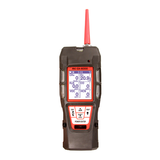
- Page 1 GX-6000 Operator’s Manual Part Number: 71-0362 Revision: F Released: 11/6/17 www.rkiinstruments.com...
- Page 2 Typical calibration frequencies for most applications are between 1 and 3 months, but can be required more often or less often based on your usage. GX-6000 Operator’s Manual...
-
Page 3: Table Of Contents
About the GX-6000 ........ - Page 4 Start Up ........... . 19 Turning On the GX-6000 ....... . . 19 Performing a Demand Zero .
- Page 5 Replacing the Probe’s Particle Filter and Hydrophobic Filter Disk ..115 Replacing the H S Scrubber Disk and the Charcoal Filter ... . 117 GX-6000 Operator’s Manual Table of Contents...
- Page 6 Updating the Datalogging Parameters ..... . 168 Adjusting the Low Flow Setpoint ......170 Table of Contents GX-6000 Operator’s Manual...
- Page 7 IR CO2 Start Up and Normal Operation ......197 Performing a Demand Zero for Carbon Dioxide Sensors ..197 GX-6000 Operator’s Manual Table of Contents...
- Page 8 Start Up, Bar Hole Mode ........216 Turning on the GX-6000, Bar Hole Mode ....216 Performing a Fresh Air Adjustment, Bar Hole Mode .
- Page 9 Not tested in oxygen enriched atmospheres (above 21%). NOTE: RKI Instruments, Inc. recommends that you refer to ISA-RP12.13, Part II-1987 or an equivalent international recommended practice for guidance in the use of combustible gas detection instruments.
-
Page 10: Chapter 1: Introduction
The GX-6000 offers a full range of features including: • Simultaneous monitoring of one to six gases. - Page 11 • CSA “C/US” classification for Class I, Division I, Groups A, B, C, and D hazardous atmospheres WARNING: The Model GX-6000 detects oxygen deficiency, elevated levels of oxygen, combustible gases, carbon monoxide, and hydrogen sulfide, all of which can be dangerous or life threatening.
-
Page 12: Specifications
42.0 ppm * When calibrating the GX-6000 with the Auto Calibration or the Single Calibration method, the calibration gas value must be equal to or higher than the alarm 1 setting. See “Updating the Alarm Point Settings” on page 157 for instructions to change the alarm points if necessary for the desired calibration gas value. - Page 13 • Tapered nozzle • Screen protector • 3 foot hose and probe • VOC zero filter (included for instruments with a low range PID sensor, a 10.0 eV/benzene PID sensor, or any PID/IR CO combination) GX-6000 Operator’s Manual Specifications • 4...
- Page 14 • IrDA/USB Cable for connecting to a computer when using the Data Logger Management Program (not needed if computer has an infrared port) Dimensions Approximately 200(H) x 68(W) x 52(D) mm (7.9”H x 2.7”W x 2.0”D) and Weight Approximately 400 g (14 oz.) 5 • Specifications GX-6000 Operator’s Manual...
-
Page 15: About This Manual
• Appendix C describes the ESS-03 sensors and the operation of the GX- 6000 with an ESS-03 sensor installed. • Appendix D describes the IR sensors and the operation of the GX-6000 with an IR sensor installed. • Appendix E describes the operation of the GX-6000 in Leak Check Mode. -
Page 16: Chapter 2: Description
The case is dust proof and water resistant. A clear plastic window is located on the front of the case. The battery pack and flow chamber are located on the back of the GX-6000. The inlet filter holder is located on the top of the GX-6000 case. -
Page 17: Lcd
• allows you to exit a menu without saving changes • locks screen orientation in any mode if INVERSION SELECT is set to ON • activates the demand zero function (adjusts the GX-6000’s fresh air reading) • enters instructions into the GX-6000’s microprocessor •... -
Page 18: Alarm Leds
GX-6000 because of flow rate reduction. Flow Chamber The flow chamber is on the back of the GX-6000 and is held in place by four phillips screws. The flow chamber seals to the rubber sensor gasket which seals to the sensor faces inside the GX-6000 and routes flow from the pump to the sensors and to the exhaust port (on the top of the GX-6000 case). -
Page 19: Sensors
6000’s circuitry, converted to a measurement of gas concentration, and displayed on the LCD. PID Sensor Two types of PID sensors can be used with the GX-6000, a low range (higher sensitivity) sensor and a high range (lower sensitivity) sensor (see Table 1 for specifications). -
Page 20: Filters
The filter holder is a clear plastic dome shaped piece on the top of the case. A male quick connect fitting is located on the inlet filter holder. This is the GX-6000’s inlet fitting. The filter holder may be removed by turning it counterclockwise and pulling it away from the case. One flat membrane disk hydrophobic filter, a wire mesh disk, and a rubber filter retaining gasket are 11 •... -
Page 21: Batteries
The lithium ion battery pack can be recharged by placing the GX-6000 in its battery charging station or by placing the battery pack in the charging station. -
Page 22: Included Accessories
A protective rubber boot can be installed over the GX-6000. Wrist Strap A wrist strap is included with the GX-6000 and can be attached to the right or left wrist strap installation feature on the GX-6000 case. Sample Hose and Probe A 3 foot sample hose with an attached probe is standard with the GX-6000. -
Page 23: Screen Protector
6 . Use needle-nose pliers or tweezers to handle the screen protector. 7 . Align the top of the screen protector with the top of the “RKI GX-6000” logo. 8 . Press down on the center of the screen protector. Water should spread out along the entire surface of the screen protector between the screen protector and the LCD. -
Page 24: Other Accessories
12 . Reinstall the rubber boot. Other Accessories Several other accessories are available for the GX-6000. This section describes the VOC zero filter, the dilution fitting, and the DIN rail. Detailed instructions regarding the use of the dilution fitting are included in other parts of this manual. -
Page 25: External Dilution Fitting
External Dilution Fitting A 1:1 external dilution fitting is available for the GX-6000. It is designed to mate with the inlet fitting and accept the sample hose and probe. The fitting is made with brass and nickel plated brass and is appropriate for use with the four standard gases. - Page 26 3 . Slide the charger(s) along the DIN rail into the desired position. 4 . Install the end clamps on the left and right side of the charger or bank of chargers to prevent sliding. DIN Rail Clamp Figure 7: Clamp Installation 17 • Other Accessories GX-6000 Operator’s Manual...
- Page 27 5 . To remove any charger(s) from the DIN rail: a. Remove the clamps by pushing on the bottom of the clamp and pulling on the top of the clamp. b. Slide the charger(s) off the DIN rail. Figure 10: Charger Removal GX-6000 Operator’s Manual Other Accessories • 18...
-
Page 28: Chapter 3: Operation
REMINDER, and ID DISPLAY. If any of these items are turned off, then the corresponding screens will not appear. The GX-6000 may be used with a sample hose and probe or with the tapered rubber nozzle. Determine which configuration works best for your application. - Page 29 • To continue accumulating peak and time-weighted average (TWA) readings from the last time the GX-6000 was used, press and release the POWER/ENTER button before the countdown reaches 0 or allow the countdown to reach 0. If you do not press the POWER/ENTER button within the 5 second countdown, the GX-6000 automatically resumes accumulating the peak and TWA readings.
- Page 30 NO : RESET To perform a calibration, press and release the POWER/ENTER button. The GX-6000 will enter Calibration Mode and the LCD will show the Calibration Mode main menu. See “Chapter 4: Calibration Mode” on page 68 for instructions to calibrate the GX-6000. When you are done with the calibration and exit Calibration Mode, the unit will begin the startup sequence.
- Page 31 The GX-6000 cannot be used until a successful calibration has been performed. Press and release the POWER/ENTER button to enter Calibration Mode. See “Chapter 4: Calibration Mode” on page 68 for instructions to calibrate the GX-6000. NOTE: In this situation, even if the User password function has been turned on, no password is required to perform a calibration.
- Page 32 The GX-6000 will enter Calibration Mode and the LCD will show the Calibration Mode main menu. See “Chapter 4: Calibration Mode” on page 68 for instructions to bump test the GX-6000. When you are done with the bump test and exit Calibration Mode, the unit will begin the startup sequence.
- Page 33 BUMP DATE PAST CANNOT USE CAL MODE : ENTER The GX-6000 cannot be used until a successful bump test has been performed. Press and release the POWER/ENTER button to enter Calibration Mode. See “Chapter 4: Calibration Mode” on page 68 for instructions to bump test the GX-6000.
- Page 34 NOTE: If CAL REMINDER or BUMP REMINDER or both are set to OFF, a WARM-UP screen will display before the warm up sequence continues. 6 . The Date/Time Screen appears for a few seconds. 4:07 DATE 4/ 1/15 DD/MM/YYYY 4:07 25 • Start Up GX-6000 Operator’s Manual...
- Page 35 BATTERY VOLTAGE 4.5V BATTERY TYPE ALKALINE LATCHING 8 . The Active Gases Screen appears for a few seconds indicating which channels are active and their target gas. SMART 1 Isobutylene %LEL 10.6 eV GX-6000 Operator’s Manual Start Up • 26...
- Page 36 On or Off” on page 160), the User ID Screen appears for a few seconds, followed by the Station ID Screen. 4:07 4:07 USER ID STATION ID KIMBERLY TANK 5 If ID DISPLAY is set to OFF, these screens will not appear. 27 • Start Up GX-6000 Operator’s Manual...
-
Page 37: Performing A Demand Zero
11 . If the GX-6000 experiences a sensor failure during start up, a screen indicating which sensor failed appears and the buzzer sounds a double pulsing tone once per second. In the example below, the CH sensor has failed. SENSOR... -
Page 38: Turning Off The Gx-6000
5 . Continue to hold the AIR button until the LCD prompts you to release it. The GX-6000 will set the fresh air reading for all channels. Start up is complete and the unit is now ready for monitoring. 6 . If the VOC zero filter was used, remove the filter from the GX-6000’s inlet fitting or probe. -
Page 39: Monitoring An Area
Monitoring an Area 1 . Start up the GX-6000 as described above in “Start Up” on page 19. It is now in Measuring Mode. 4:07 20.9 %LEL 2 . Take the GX-6000 to the monitoring area. Put the probe tip in the area to be monitored. -
Page 40: Using Optional Sample Hoses
Using Optional Sample Hoses The standard sample hose for the GX-6000 is 3 feet long. Optional samples hoses and probes with longer hoses are available from 5 - 50 feet in 5 foot increments (see “General Parts List” on page 137). If you are considering using a hose and probe with a longer hose, keep in mind that a longer hose will increase the GX-6000’s response time and the flowrate may decrease... - Page 41 Xylene 4.27 2.78 • The GX-6000 provides the catalytic combustible sensor with some protection against exposure to high levels of combustible gas which can damage the sensor. It does this by turning off the combustible sensor power temporarily when it determines that an over scale (more than 100 %LEL) concentration of combustible gas is present that may damage the sensor.
-
Page 42: Voc Detection
Minimize the sensor’s exposure to these gases as much as possible. If exposure occurs, allow the instrument to draw fresh air and confirm that the readings return to fresh air values. 33 • Measuring Mode, Normal Operation GX-6000 Operator’s Manual... -
Page 43: Snap Log Mode
DISP/LOCK button to exit Snap Log Mode without saving a set of snap log data. The third screen displays the year, month, day, and time of the snap log. The fourth screen displays the current gas readings. GX-6000 Operator’s Manual Measuring Mode, Normal Operation • 34... - Page 44 NOTE: If the GX-6000 detects an alarm condition while in Snap Log Mode, it will automatically exit Snap Log Mode and return to Measuring Mode. You may then reenter Snap Log Mode and take snap logs while the instrument is still in alarm.
-
Page 45: Measuring Mode, Alarms
Measuring Mode, Alarms This section covers alarm indications in Measuring Mode. It also describes how to reset the GX-6000 after an alarm has occurred and how to respond to an alarm condition. NOTE: False alarms may be caused by radio frequency (RF) or electromagnetic (EMI) interference. - Page 46 • Alarm LED arrays flash once per second Clock Failure • FAIL CLOCK appears at the Double pulsing tone top of the screen once per second • Alarm LED arrays flash once per second 37 • Measuring Mode, Alarms GX-6000 Operator’s Manual...
-
Page 47: Responding To Alarms
Responding to Gas Alarms 1 . Determine which gas alarm has been activated. 2 . Follow your established procedure for an increasing gas condition or a decreasing oxygen condition. GX-6000 Operator’s Manual Measuring Mode, Alarms • 38... - Page 48 Responding to Over Range Alarms WARNING: An over range condition may indicate an extreme combustible gas, toxic gas, or oxygen concentration. Confirm a normal condition with a different GX-6000 or with another gas detecting device. CAUTION: High off-scale readings may indicate an explosive concentration.
- Page 49 3 . Reset the alarm using the RESET button once the alarm condition has cleared. 4 . Calibrate the GX-6000 as described in “Chapter 4: Calibration Mode” on page 68. 5 . If the over range condition continues or if you are not able to successfully calibrate the unit, you may need to replace the sensor that has triggered the over range alarm.
- Page 50 2 . Attempt to change the date using the DATE menu item in Maintenance Mode. See “Setting the Date and Time” on page 147. 3 . If the date cannot be set correctly, contact RKI Instruments, Inc. as soon as possible.
- Page 51 3 . If the error code is anything but 022 as shown above, the instrument cannot be used. Contact RKI Instruments, Inc. as soon as possible. If the error code is 022, you may press and release the RESET button to continue into Measuring Mode if the instrument must be used temporarily.
-
Page 52: Display Mode
Two other operating modes are accessible when the GX-6000 is in Measuring Mode. They are Display Mode and Calibration Mode. This section describes using the GX-6000 in Display Mode. See Table 9 below for a list of Display Mode’s menu items, a short description of each item, and the page number for further description. -
Page 53: Tips For Using Display Mode
20 seconds. If you do not press a button within 20 seconds, the GX- 6000 automatically returns to Measuring Mode. If the Pump Off Screen is used to turn the instrument’s pump off, the Pump Off Screen will display until you turn the pump back on. GX-6000 Operator’s Manual Display Mode • 44... -
Page 54: Pid Gas Name Screen
At the top of the letter list, there is a User List item and a Recent List item. The User List can hold 30 gas names and the GX-6000 Data Logger Management Program is required to configure this list. The Recent List can hold up to 8 gas names and is made up of the 8 most recently used gas names. - Page 55 POWER/ENTER button when the cursor is next to the desired gas name. The number in the upper left corner is the gas’s number in relation to all other gas names that are stored in the GX-6000. The chemical formula is displayed next to the gas number. The response factor relative to isobutylene is listed on the second line.
-
Page 56: Peak Screen
Peak Screen The peak screen displays the highest (lowest for oxygen) concentrations detected since the GX-6000 was turned on. Peak readings are stored in the GX-6000’s memory until a higher level is detected (lower for oxygen), the peak reading is cleared, or the GX-6000 is turned off. -
Page 57: Stel Screen
If LUNCH BREAK is set to OFF, the TWA is cleared when the GX-6000 is turned off. If LUNCH BREAK is set to ON, the GX-6000 will remember TWA readings when it is turned off so it can continue them when it is turned on again. -
Page 58: View Alarm Settings Screen
POWER/ENTER button. The Full Scale Settings screen will appear showing full scale settings for each channel. Use the AIR and SHIFT (PANIC) buttons to scroll through the Warning, Alarm, STEL, and TWA settings. 49 • Display Mode GX-6000 Operator’s Manual... - Page 59 LED’s, and vibration will activate. Press and release the POWER/ ENTER button again to stop the simulated alarm. 3 . Press and release the DISP/LOCK button to return to the View Alarm Settings Screen. GX-6000 Operator’s Manual Display Mode • 50...
-
Page 60: Time In Operation Screen
With LUNCH BREAK set to OFF, the time in operation is reset when the GX-6000 is turned off. See “Updating the Lunch Break Setting” on page 161 for a description of the lunch break feature. -
Page 61: Log Time Remaining Screen
The LOG CLEAR screen asks if you want to clear the data logger memory. DISP LOG CLEAR YES :ENTER NO :DISP EXIT :RESET To continue through Display Mode without clearing the log data, press and release the DISP/LOCK button. GX-6000 Operator’s Manual Display Mode • 52... - Page 62 POWER/ENTER button. The unit will display the following screen as it clears the data. DISP LOG CLEAR CLEAR 4 . When the instrument has cleared the data, it will return to the LOG CLEAR screen in Display Mode. 53 • Display Mode GX-6000 Operator’s Manual...
-
Page 63: Pump Off Screen
Pump Off Screen WARNING: The GX-6000 is not a gas monitoring device while the pump is off. NOTE: The item appears in Display Mode only if the PUMP OFF DISP menu item in Maintenance Mode is turned ON. The factory setting for PUMP OFF DISP is OFF. -
Page 64: Select User Id Screen
Maintenance Mode is set to ON. Use this screen to select a user ID from the user ID list in the GX-6000’s memory. The current user ID is displayed. A user ID can be up to 16 characters long. The GX-6000 can store up to 128 user IDs. - Page 65 DISP/LOCK button. You will return to the Select User ID screen without saving the user ID change. 4 . The unit will save the selected user ID as the current one and will return you to the Select User ID Screen. GX-6000 Operator’s Manual Display Mode • 56...
-
Page 66: Select Station Id Screen
Maintenance Mode is set to ON. Use this screen to select a station ID from the station ID list in the GX-6000’s memory. The current station ID is displayed. A station ID can be up to 16 characters long. The GX-6000 can store up to 128 station IDs. - Page 67 DISP/LOCK button. You will return to the Select Station ID screen without saving the station ID change. 4 . The unit will save the selected station ID as the current one and return you to the Select Station ID Screen. GX-6000 Operator’s Manual Display Mode • 58...
-
Page 68: Viewing Snap Logger Data
The last line of the screen indicates the Station ID that was used for the snap log. 3 . Use the AIR and SHIFT (PANIC) buttons to scroll through different snap log IDs. 59 • Display Mode GX-6000 Operator’s Manual... -
Page 69: Peak Bar Screen
1 . With the Peak Bar Screen displayed, press and release the POWER/ ENTER button. The current setting will be displayed. 2 . Use the AIR and SHIFT (PANIC) buttons to display the desired setting. GX-6000 Operator’s Manual Display Mode • 60... -
Page 70: Gas Display Screen
POWER/ENTER button to scroll through all active channels. If the POWER/ENTER button is not pressed and released, the instrument will display the same channel’s readings for the duration of the operating session. 61 • Display Mode GX-6000 Operator’s Manual... -
Page 71: Lcd Flip Screen
LOCK button until the LOCK symbol disappears. NOTE: Even if INVERT SELECT is set to ON, the screens in Calibration Mode, User Mode, and Maintenance Mode will not flip if the instrument is turned upside down. GX-6000 Operator’s Manual Display Mode • 62... -
Page 72: Combustible Sensor Protection Screen
If combustible gas levels greater than 100 %LEL are expected, the catalytic LEL sensor can be disabled to protect it. If the catalytic LEL sensor is disabled, there will be no %LEL alarms in Measuring Mode. DISP CAT (LEL) SENSOR PROTECTION 63 • Display Mode GX-6000 Operator’s Manual... -
Page 73: Lcd Background Color Flip Screen
LCD text will be black. DISP LCD BACKGROUND YES :ENTER NO :DISP EXIT :RESET 1 . With the LCD Background Flip Screen showing, press and release the POWER/ENTER button. The current setting will be displayed. GX-6000 Operator’s Manual Display Mode • 64... -
Page 74: Language Screen
CONFIRM ? 2 . Press and release the POWER/ENTER button again to confirm the change. To return to the Language Screen without changing the instrument’s language to English, press and release the DISP/LOCK button. 65 • Display Mode GX-6000 Operator’s Manual... -
Page 75: Data Logging
RKI Instruments, Inc. The data logging capacity depends on how often the GX-6000 stores data, how many channels are active, and how often the GX-6000 is turned on and off. The table below illustrates how much data logging time is available for the various interval times. - Page 76 300 hours 10 minutes 600 hours For a complete description of the Data Logger Management Program and procedures for downloading data to a computer, see the GX-6000 Data Logger Management Program Operator’s Manual. 67 • Data Logging GX-6000 Operator’s Manual...
-
Page 77: Chapter 4: Calibration Mode
• Perform a span adjustment on one channel at a time using single calibration • Perform a bump test NOTE: You can set up the GX-6000 to alert you during the startup sequence when calibration is due. See “Updating the Calibration Reminder Setting” on page 149. -
Page 78: Calibration Supplies And Equipment
100% nitrogen is recommended for setting the oxygen zero. CAUTION: When using auto calibration, although the GX-6000 can be calibrated with an oxygen concentration of up to 19.5%, RKI Instruments, Inc. recommends that the multi-gas cylinder have an oxygen concentration in the range of 10% - 16% oxygen. -
Page 79: Entering Calibration Mode
AIR CAL AUTO CAL SINGLE CAL NORMAL MODE NOTE: The following screens illustrate a five-gas GX-6000 for detection of (%LEL using catalytic sensor), oxygen, H S, CO, and VOCs (PID sensor). Your GX-6000 may display slightly different screens. GX-6000 Operator’s Manual... -
Page 80: Calibrating Using The Auto Calibration Method
RKI 5-gas calibration cylinder (high range PID only) or an RKI 4-gas cylinder and an RKI PID cylinder and is the quickest and easiest method to calibrate the GX-6000. See Table 16 on page 137 for available cylinders. Make sure your calibration cylinder is appropriate for the PID detection range. - Page 81 7 . To continue with the fresh air adjustment, press and hold the button. If you do not want to continue, press and release the DISP/LOCK button and the unit will return to the Calibration Mode Screen. GX-6000 Operator’s Manual Calibrating Using the Auto Calibration Method • 72...
- Page 82 8 . The GX-6000 will indicate that it is adjusting the zero reading for a few seconds and then it will prompt you to release the AIR button. AIR CAL AIR CAL AIR CAL HOLD AIR KEY HOLD AIR KEY...
-
Page 83: Performing A Span Adjustment
2 . Connect the sample tubing to the demand flow regulator. 3 . Install the sample hose and probe on the GX-6000 inlet fitting. Make sure the probe’s two halves are tightened firmly together to avoid leaks that can affect the calibration. See Figure 22, “Replacing the Particle Filter and Hydrophobic Filter Disk”... - Page 84 Settings” on page 157 for instructions. If you need to change the alarm point setting only to perform a calibration, make sure that you change the alarm point setting back to its original value once the calibration has been performed. 75 • Calibrating Using the Auto Calibration Method GX-6000 Operator’s Manual...
- Page 85 13 . Press and release the POWER/ENTER button. The instrument returns to the Auto Cal Menu. 14 . Use the AIR and SHIFT (PANIC) buttons to move the cursor next to GAS SELECT. AUTO AUTO CAL CONCENTRATION GAS SELECT ESCAPE GX-6000 Operator’s Manual Calibrating Using the Auto Calibration Method • 76...
- Page 86 16 . With the standard four sensors screen displayed, press and release the POWER/ENTER button to proceed to the Calibration In Process Screen with APPLYGAS and the gas readings flashing. APPLYGAS 20.9 %LEL 77 • Calibrating Using the Auto Calibration Method GX-6000 Operator’s Manual...
- Page 87 If you do want to continue with the calibration, proceed to the next step. 17 . Connect the tubing from the demand flow regulator to the rigid tube on the probe. Allow the GX-6000 to draw gas for one minute. 18 . Press and release the POWER/ENTER button to set the span adjustment for each channel to the programmed values.
- Page 88 Leave the tubing connected to the rigid tube on the probe. Continue with Step 23. 23 . Use the AIR and SHIFT (PANIC) buttons to move the cursor next to GAS SELECT. AUTO AUTO CAL CONCENTRATION GAS SELECT ESCAPE 79 • Calibrating Using the Auto Calibration Method GX-6000 Operator’s Manual...
- Page 89 AUTO AUTO GAS SELECT GAS SELECT 50 %LEL AIR or 12.0 SHIFT (PANIC) 25.0 AUTO GAS SELECT AIR or AIR or SHIFT (PANIC) SHIFT (PANIC) ESCAPE GX-6000 Operator’s Manual Calibrating Using the Auto Calibration Method • 80...
- Page 90 If you do not want to proceed with the calibration, press and release the DISP/LOCK button to return to the Gas Select Screen. If you do want to continue with the calibration, proceed to the next step. 81 • Calibrating Using the Auto Calibration Method GX-6000 Operator’s Manual...
- Page 91 If you are using a PID only calibration cylinder: a. Connect the tubing from the regulator to the rigid tube on the probe. Allow the GX-6000 to draw gas for one minute. b. Press and release the POWER/ENTER button to set the span adjustment for the PID channel to the programmed value.
-
Page 92: Returning To Measuring Mode
4 . Use the SHIFT (PANIC) button to place the cursor next to the NORMAL MODE menu option, then press and release the POWER/ ENTER button to return to Measuring Mode. 83 • Calibrating Using the Auto Calibration Method GX-6000 Operator’s Manual... -
Page 93: Calibrating Using The Single Calibration Method
(PANIC) button. CAL MODE AIR CAL AUTO CAL SINGLE CAL NORMAL MODE 2 . Press and release the POWER/ENTER button. The Fresh Air Reading Screen will be displayed. 20.9 %LEL GX-6000 Operator’s Manual Calibrating Using the Single Calibration Method • 84... - Page 94 If you do not want to continue, press and release the DISP/LOCK button and the unit will return to the Calibration Mode Screen. 5 . The GX-6000 will indicate that it is adjusting the zero reading for a few seconds and then it will prompt you to release the AIR button.
-
Page 95: Performing A Span Adjustment In Single Calibration
SINGLE CAL NORMAL MODE ZERO ADJUSTED 7 . If the VOC zero filter was used, remove the filter from the GX-6000’s inlet fitting or probe. Reinstall the plugs on each end of the filter. Performing a Span Adjustment in Single Calibration 1 . - Page 96 Gas Name Screen in Display Mode. In the example below, acetone is the currently selected gas. If isobutylene is the selected gas, then isobutylene will appear twice in this list. SINGLE GAS SELECT Isobutylene Acetone ESCAPE 87 • Calibrating Using the Single Calibration Method GX-6000 Operator’s Manual...
- Page 97 %LEL 11 . Connect the tubing from the demand flow regulator to the rigid tube on the probe. Allow the GX-6000 to draw gas for one minute. 12 . If necessary, adjust the reading to match the cylinder concentration with AIR and SHIFT (PANIC) buttons.
- Page 98 19 . Use the SHIFT (PANIC) button to place the cursor next to the NORMAL MODE menu item, then press and release the POWER/ ENTER button to return to Measuring Mode. 89 • Calibrating Using the Single Calibration Method GX-6000 Operator’s Manual...
-
Page 99: Performing A Bump Test
1 . Install the demand flow regulator onto the calibration cylinder. 2 . Connect the sample tubing to the demand flow regulator. 3 . Install the sample hose and probe on the GX-6000 inlet fitting. Make sure the probe’s two halves are tightened firmly together to avoid leaks that can affect the calibration. - Page 100 NORMAL MODE 7 . Move the cursor next to the BUMP TEST menu item by using the SHIFT (PANIC) button. CAL MODE AIR CAL AUTO CAL SINGLE CAL BUMP TEST NORMAL MODE 91 • Performing a Bump Test GX-6000 Operator’s Manual...
- Page 101 If they are not, adjust the bump test gas value(s) be entering the AUTO CAL menu item in Calibration Mode, changing the value(s) there, and reentering the BUMP TEST menu item. GX-6000 Operator’s Manual Performing a Bump Test • 92...
- Page 102 ENTER button. If one or more sensors fail the bump test, see “Troubleshooting” on page 104 to investigate the cause of the failure and replace the failed sensor or sensors if necessary. 93 • Performing a Bump Test GX-6000 Operator’s Manual...
- Page 103 BUMP SETTING menu item in Maintenance Mode. 60CAL 19.0 %LEL 23.0 GX-6000 Operator’s Manual Performing a Bump Test • 94...
- Page 104 16 . Use the SHIFT (PANIC) button to place the cursor next to the NORMAL MODE menu option, then press and release the POWER/ ENTER button to return to Measuring Mode. 95 • Performing a Bump Test GX-6000 Operator’s Manual...
-
Page 105: Chapter 5: User Mode
Chapter 5: User Mode Overview This section describes the GX-6000 in User Mode. See Table 12 below for a list of the items found in User Mode, the page that the menu item’s instructions can be found on, and a short description of the menu item. -
Page 106: Entering User Mode
WARNING: The GX-6000 is not in operation as a gas detector while in User Mode. 1 . Take the GX-6000 to a non-hazardous location and turn it off if it is on. 2 . Press and hold the AIR and SHIFT (PANIC) buttons, then press and hold the POWER/ENTER button. -
Page 107: Setting The Date And Time
4 . Press and release POWER/ENTER to save the setting. The month setting flashes. 5 . Repeat Step 3 and Step 4 to enter the month, day, hours, and minutes settings. The main menu displays after you enter the seconds setting. GX-6000 Operator’s Manual Setting the Date and Time • 98... -
Page 108: Setting The Date Format
3 : H2S (H2S ) 4 : CO (CO ) 5 : VOC (SM1) ESCAPE 3 . Use AIR or SHIFT (PANIC) to move the cursor next to the channel you want to configure. 99 • Setting the Date Format GX-6000 Operator’s Manual... - Page 109 8 . Use SHIFT (PANIC) to move the cursor next to the ESCAPE menu item. NOTE: If you want to exit to the main menu without saving any channel configuration changes, press and release DISP/LOCK. GX-6000 Operator’s Manual Configuring the Channels • 100...
-
Page 110: Updating The Language Setting
LOCK. The unit will return to the main menu. 4 . Press and release POWER/ENTER to save the new language setting and return to the main menu. The GX-6000’s user interface will now be in the newly selected language. Viewing the ROM/SUM of the Instrument The ROM/SUM screen shows the firmware version that is loaded in the instrument and the firmware checksum. -
Page 111: Turning The Password Function On Or Off
Turning the Password Function On or Off With PASSWORD set to ON, the GX-6000 prompts you for a password when you enter User Mode and Calibration Mode. With PASSWORD set to OFF (factory setting), no password is required to enter User Mode or Calibration Mode. -
Page 112: Exiting User Mode
1 . From the main menu, place the cursor in front of START MEASURE at the bottom of the menu. 2 . Press and release POWER/ENTER. 3 . The unit will begin its start-up sequence. 103 • Exiting User Mode GX-6000 Operator’s Manual... -
Page 113: Chapter 6: Maintenance
Chapter 6: Maintenance Overview This chapter describes troubleshooting procedures for the GX-6000. It also includes procedures for replacing and recharging the batteries and replacing various consumable parts. WARNING: RKI Instruments, Inc. recommends that service, calibration, and repair of RKI Instruments be performed by personnel properly trained for this work. - Page 114 • The auto calibration 1. Check all calibration tubing for leaks or for any bad connections. single calibration values may not match the 2. Make sure the GX-6000 has fails. cylinder gas been properly set up for concentrations (auto calibration.
-
Page 115: Replacing Or Recharging The Batteries
1 . Turn off the GX-6000. WARNING: Do not remove the batteries while the GX-6000 is on. 2 . Turn the GX-6000 over so that the flow chamber and battery cover are facing up and the LCD is facing down. - Page 116 4 . Grasp the end of the battery cover that’s closest to the bottom of the instrument and lift it up. Figure 12: Opening Battery Cover 5 . Carefully remove the old alkaline batteries. Verify that the battery compartment and electrical contacts are clean. 107 • Replacing or Recharging the Batteries GX-6000 Operator’s Manual...
-
Page 117: Replacing The Lithium Ion Battery Pack
WARNING: Do not remove the battery pack while the GX-6000 is on. 2 . Remove the rubber boot, if installed. 3 . Turn the GX-6000 over so that the flow chamber and battery cover are facing up and the LCD is facing down. - Page 118 9 . Reinstall the rubber boot, if desired. 109 • Replacing or Recharging the Batteries GX-6000 Operator’s Manual...
-
Page 119: Recharging The Lithium Ion Battery Pack
RKI charger model BC-6000DC, p/n 49-2183. Use of other rechargeable batteries or chargers or charging of other rechargeable batteries in the GX-6000 will void the warranty. PRUDENCE:Pour être utilisé uniquement avec une batterie au lithium-ion p/n 49-1619. Charge uniquement en fonction du modèle de chargeur RKI BC-6000, p/n 49-2182, ou modèle de chargeur... - Page 120 One adapter will not operate more than one charging station. 4 . Place the GX-6000 into the battery charging station as shown in Figure 18 below so that the metal contacts on the back of the unit come into contact with the metal contacts on the back of the holder in the charging station.
-
Page 121: Recharging The Lithium Ion Battery Pack Out Of The Instrument
The lithium ion battery pack may be charged using the charging station while it is out of the GX-6000. This is useful if spare battery packs are kept in case the pack in the GX-6000 needs to be charged, but the unit must be used immediately. - Page 122 3 . If using an AC powered charging station, plug the AC adapter into an electrical outlet. AC Power Supply Power Supply Jack (on bottom of charger) DC12V To AC Outlet AC Powered Charging Station Figure 19: Connecting the Charging Station’s AC Adapter 113 • Replacing or Recharging the Batteries GX-6000 Operator’s Manual...
- Page 123 One adapter will not operate more than one charging station. 4 . If necessary, remove the battery pack from the instrument as described in Step 1 - Step 6 in “Replacing the Lithium Ion Battery Pack” on page 108. GX-6000 Operator’s Manual Replacing or Recharging the Batteries • 114...
-
Page 124: Replacing The Probe's Particle Filter And Hydrophobic Filter Disk
Replacing the Probe’s Particle Filter and Hydrophobic Filter Disk Inspect the probe’s internal components if you notice that the GX-6000’s pump sounds bogged down or if an unexplained low flow alarm occurs. Replace the particle filter and hydrophobic filter disk if they appear dirty or saturated with liquid. - Page 125 7 . Set the new particle filter on top of the filter disk. The bigger end should be facing down. GX-6000 Operator’s Manual Replacing the Probe’s Particle Filter and Hydrophobic Filter...
-
Page 126: Replacing The H 2 S Scrubber Disk And The Charcoal Filter
2 . Use a small Phillips screwdriver to unscrew the four screws holding the flow chamber to the rest of the GX-6000’s case. 3 . Grasp the sides of the flow chamber and lift it away from the rest of the case. - Page 127 H2S Scrubber Disk Charcoal Filter Sensor G asket Figure 23: Replacing the H S Scrubber Disk and Charcoal Filter GX-6000 Operator’s ManualReplacing the H S Scrubber Disk and the Charcoal Filter • 118...
- Page 128 Turn the GX-6000 on. b. Plug the inlet with your finger. c. Verify that the GX-6000 goes into low flow alarm. If the GX-6000 does not go into low flow alarm, turn the instrument off and attempt to seat the sensor gasket again.
-
Page 129: Replacing A Sensor
2 . Use a small Phillips screwdriver to unscrew the four screws holding the flow chamber to the rest of the GX-6000’s case. 3 . Grasp the sides of the flow chamber and lift it away from the rest of the case. - Page 130 Make sure that the flat side is up and the hollow side is down. 8 . Place the sensor gasket and filters back over the sensors ensuring that the sensor gasket seals with the sensors and the flow fittings. The flow 121 • Replacing a Sensor GX-6000 Operator’s Manual...
- Page 131 9 . Insert the flow chamber back into the instrument. 10 . Tighten the flow chamber’s four screws that were loosened in Step 2. 11 . Start up the GX-6000 by pressing and briefly holding the POWER/ ENTER button. 12 . To verify that the sensor gasket was inserted properly: a.
-
Page 132: Replacing The Hydrophobic Filter And Wire Mesh Disk
Wire Mesh Disk 1. Verify that the GX-6000 is off. 2. Locate the clear plastic filter holder at the top of the GX-6000. 3. Grasp the filter holder and turn it 1/4 turn counterclockwise. 4. Pull the filter holder away from the case. -
Page 133: Pid Sensor Maintenance
2 . Use a small Phillips screwdriver to unscrew the four screws holding the flow chamber to the rest of the GX-6000’s case. 3 . Grasp the sides of the flow chamber and lift it away from the rest of the case. - Page 134 Take care not to touch the lamp window, the flat end of the lamp, with your fingers. If the lamp remains lodged in the sensor body, carefully remove it with tweezers. Lamp Window Figure 29: Lamp Window Location 125 • PID Sensor Maintenance GX-6000 Operator’s Manual...
- Page 135 Take care not to touch the tip of the cotton swab that is used to clean the lamp as this may contaminate it with finger oil. 17 . Ensure the lamp is completely dry and any visible signs of contamination are removed before reinstalling. GX-6000 Operator’s Manual PID Sensor Maintenance • 126...
- Page 136 25 . Place the sensor gasket and filters back over the sensors ensuring that it seals with the sensors and the flow fittings. The flow fitting connections need to be facing up and cannot be skewed sideways. The gasket must be 127 • PID Sensor Maintenance GX-6000 Operator’s Manual...
- Page 137 26 . Insert the flow chamber back into the instrument. 27 . Tighten the flow chamber’s four screws that were loosened in Step 2. 28 . Start up the GX-6000 by pressing and briefly holding the POWER/ ENTER button. 29 . To verify that the sensor gasket was inserted properly: a.
-
Page 138: Replacing The Pid Sensor's Lamp
2 . Use a small Phillips screwdriver to unscrew the four screws holding the flow chamber to the rest of the GX-6000’s case. 3 . Grasp the sides of the flow chamber and lift it away from the rest of the case. - Page 139 12 . Discard the old PID lamp. NOTE: At this point it is recommended that the finger cots be used on the fingers handling the lamp. Finger cots are included with the lamp cleaning kit. GX-6000 Operator’s Manual PID Sensor Maintenance • 130...
- Page 140 20 . Place the sensor gasket and filters back over the sensors ensuring that it seals with the sensors and the flow fittings. The flow fitting connections need to be facing up and cannot be skewed sideways. The gasket must be 131 • PID Sensor Maintenance GX-6000 Operator’s Manual...
- Page 141 21 . Insert the flow chamber back into the instrument. 22 . Tighten the flow chamber’s four screws that were loosened in Step 2. 23 . Start up the GX-6000 by pressing and briefly holding the POWER/ ENTER button. 24 . To verify that the sensor gasket was inserted properly: a.
-
Page 142: Replacing The Pid Sensor's Electrode Stack
Replacing the PID Sensor’s Electrode Stack The electrode stack can last for the life of the PID sensor if the GX-6000 is used in a very clean, controlled environment. When used in a heavily contaminated or dirty environment, the electrode stack may only last a month. - Page 143 O-ring seal in the new electrode stack with the other hand as shown below. Take care not to touch the lamp window. GX-6000 Operator’s Manual PID Sensor Maintenance • 134...
- Page 144 19 . Push the sensor into the socket until it bottoms out. 135 • PID Sensor Maintenance GX-6000 Operator’s Manual...
- Page 145 21 . Insert the flow chamber back into the instrument. 22 . Tighten the flow chamber’s four screws that were loosened in Step 2. 23 . Start up the GX-6000 by pressing and briefly holding the POWER/ ENTER button. 24 . To verify that the sensor gasket was inserted properly: a.
-
Page 146: General Parts List
General Parts List Table 16 lists part numbers for the GX-6000’s replacement parts and accessories. Table 16: General Parts List Part Number Description 06-1248RK-03 Calibration kit tubing, 3 foot length 13-0112RK Wrist strap 13-6022 DIN rail, 4” long 13-6022-01 DIN rail mounting kit for 1 charger, includes 4” DIN rail and 2 end... - Page 147 Sample hose with integral probe, with hydrophobic filter and particle filter, no scrubber section. Replace “XX” with length in feet. 3 foot hose is standard. Available lengths for the GX-6000 are 3, 5, 10, 15, 20, 25, 30, 35, 40, 45, and 50 feet.
- Page 148 ES-1827i Hydrogen sulfide (H S) sensor NC-6264A LEL combustible sensor, catalytic OS-BM2 Oxygen sensor PID-001L PID sensor, 0 - 50,000 ppb VOC, improved type PID-002 PID sensor, 0 - 6,000 ppm VOC 139 • General Parts List GX-6000 Operator’s Manual...
-
Page 149: Appendix A: Maintenance Mode
Appendix A: Maintenance Mode Overview This appendix describes the GX-6000 in Maintenance Mode. The GX-6000 is factory-set to suit most applications. Update settings in Maintenance Mode only if required for your specific application. Maintenance Mode items and their factory settings are listed in Table 17 below. - Page 150 • ON • OFF • ESCAPE return to main menu PUMP OFF DISP (pg.159) • ON • OFF ID DISPLAY (pg.160) • ON • OFF BACK LIGHT TIME (pg.160) OFF - 255 SEC 30 SEC 141 • Overview GX-6000 Operator’s Manual...
- Page 151 KEY TONE (pg.164) • ON • OFF INERT MODE (pg.164) • ON • OFF L. /B. MODE (pg.164) • OFF • LEAK CHECK MODE BAR HOLE MODE • BAR HOLE MODE • LEAK CHECK MODE GX-6000 Operator’s Manual Overview • 142...
- Page 152 • ESCAPE return to main menu FLOW ADJUST (pg.170) set the low flow alarm ROM/SUM (pg.171) view the ROM number and checksum PASSWORD (pg.171) • ON (0006) • OFF RESTORE DEFAULT (pg.172) restore default settings 143 • Overview GX-6000 Operator’s Manual...
-
Page 153: Tips For Using Maintenance Mode
WARNING: The GX-6000 is not in operation as a gas detector while in Maintenance Mode. 1 . Take the GX-6000 to a non-hazardous location and turn it off if it is on. 2 . Press and hold the AIR and SHIFT (PANIC) buttons, then press and hold the POWER/ENTER button. - Page 154 MAINTENANCE and press and release the POWER/ENTER button. A password screen will appear. Continue to Step 7. 6 . If User Mode’s PASSWORD has been set to ON, a password screen will appear. 145 • Using Maintenance Mode GX-6000 Operator’s Manual...
- Page 155 POWER/ENTER button to enter Maintenance Mode. There is no need to enter a password. The password screen appears even if PASSWORD is set to OFF so that a special factory mode can be accessed, if necessary. GX-6000 Operator’s Manual Using Maintenance Mode • 146...
-
Page 156: Setting The Date And Time
4 . Press and release POWER/ENTER to save the setting. The month setting flashes. 5 . Repeat Step 3 and Step 4 to enter the month, day, hours, and minutes settings. The main menu displays after you enter the seconds setting. 147 • Using Maintenance Mode GX-6000 Operator’s Manual... -
Page 157: Setting The Date Format
152 for instructions. Entering the BUMP TEST menu item brings you to the first of the Gas Select Screens. See “Performing a Bump Test” on page 90 for instructions, starting at Step 8. GX-6000 Operator’s Manual Using Maintenance Mode • 148... -
Page 158: Updating Calibration Settings
2 . Press and release POWER/ENTER. The CAL SETTING menu appears. Updating the Calibration Reminder Setting With CAL REMINDER set to ON (factory setting), the GX-6000 will give an indication at start up if it is due for calibration. The type of indication will depend on the CAL EXPRD setting (see “Updating the Calibration Expired... - Page 159 With CAL EXPRD set to CANNOT USE, if the unit is due for calibration, the GX-6000 will give an indication at start up that calibration is past due and will prompt you to press and release POWER/ENTER to enter Calibration Mode and perform a calibration.
-
Page 160: Updating Bump Test Settings
BUMP INTERVAL BUMP EXPRD BUMP CHECK GAS ESCAPE 1 . From the main menu, place the cursor next to BUMP SETTING. 2 . Press and release POWER/ENTER. The BUMP SETTING menu appears. 151 • Using Maintenance Mode GX-6000 Operator’s Manual... - Page 161 60 seconds, and 90 seconds. 1 . From the BUMP PARAMETERS screen, place the cursor next to GAS TIME. 2 . Press and release POWER/ENTER. The current Gas Time value will begin to flash. GX-6000 Operator’s Manual Using Maintenance Mode • 152...
- Page 162 90 seconds and the GAS TIME is set to 30 seconds, if the bump test fails, the GX-6000 will only be exposed to gas for an additional 60 seconds. The available values are 90 seconds (factory setting), and 120 seconds.
- Page 163 BUMP SETTING screen. Updating the Bump Reminder Setting With BUMP REMINDER set to ON, the GX-6000 will give an indication at start up if it is due for bump testing. The type of indication will depend on the BUMP EXPRD setting (see “Updating the Bump Expired Setting” on page 155).
- Page 164 With BUMP EXPRD set to CANNOT USE, if the unit is due for bump testing, the GX-6000 will give an indication at start up that a bump test is past due and will prompt you to press and release POWER/ENTER to enter Calibration Mode and perform a bump test.
-
Page 165: Updating Alarm Parameters
ALARM SETTING ALARM POINTS ALARM LATCHING ALARM SILENCE ESCAPE 1 . From the main menu, place the cursor next to ALARM SETTING. 2 . Press and release POWER/ENTER. The ALARM SETTING menu appears. GX-6000 Operator’s Manual Using Maintenance Mode • 156... - Page 166 Updating the Alarm Point Settings This menu item allows you to update one or more alarm points (the reading at which the GX-6000 recognizes the alarm condition). See Table 1 on page 3 for alarm point factory settings. 1 . From the ALARM SETTING menu, place the cursor next to ALARM POINTS.
- Page 167 With ALARM LATCHING set to LATCHING (factory setting), the GX- 6000 remains in alarm condition until the alarm condition passes and the RESET button is pressed. With ALARM LATCHING set to SELF RESET, the GX-6000 automatically resets an alarm when the alarm condition passes. GX-6000 Operator’s Manual...
-
Page 168: Turning The Pump On/Off Display On Or Off
Updating the Alarm Silence Setting With ALARM SILENCE set to ON (factory setting), pressing and releasing the RESET button silences the buzzer when the GX-6000 is in alarm. The LEDs continue to flash, the vibrator continues to pulse, and the display continues to show the alarm. -
Page 169: Turning The User/Station Id Function On Or Off
4 . Press and release POWER/ENTER to save the setting and return to the main menu. Updating the Language Setting This setting allows you to select the language for the GX-6000’s user interface. The available choices are English (factory setting), Japanese, Italian, Spanish, German, French, Portuguese, Russian, and Korean. -
Page 170: Updating The Lunch Break Setting
With LUNCH BREAK set to ON, the Lunch Break Screen displays during startup. From this screen, you can choose to continue accumulating TWA and PEAK readings and the time in operation from the last time the GX-6000 was used or start collecting new readings and reset the time in operation. -
Page 171: Updating The Demand Zero Setting
%LEL, it is displayed in %vol. Alarm points exist for the %LEL range but do not exist for the %vol range. If IR AUTO RANGE is set to LOW ONLY, the IR channel’s gas reading will only be displayed in %LEL up to 100 %LEL. GX-6000 Operator’s Manual Using Maintenance Mode • 162... -
Page 172: Updating The Confirmation Alert Setting
CONFIRMATION to ON. The interval can be 1 - 60 minutes. The factory setting is 5 minutes. With CONFIRMATION set to OFF (factory setting), the GX-6000 does not provide a confirmation alert. 1 . From the main menu, place the cursor next to CONFIRMATION. -
Page 173: Turning The Key Tone Noise On Or Off
With INERT MODE set to ON, Inert Mode becomes an option in the Mode Select Screen when the instrument turns on. Normal Mode is still an option. See “Appendix G: Using the GX-6000 in Inert Mode” on page 223 for a description of Inert Mode. -
Page 174: Setting The Bar Hole Measurement Time
This setting is factory set to OFF when a unit is shipped unless the instrument is ordered for bar hole measurement or leak checking use. See and “Appendix E: Using the GX-6000 in Leak Check Mode” for a discussion of Leak Check Mode. See “Appendix F: Using the GX-6000 in Bar Hole Mode”... -
Page 175: Updating The Man Down Settings
2 . Press and release POWER/ENTER. The Man Down Screen appears. 3 . Use AIR or SHIFT (PANIC) to display the desired setting. 4 . Press and release POWER/ENTER to save the setting and return to the MAN DOWN MENU screen. GX-6000 Operator’s Manual Using Maintenance Mode • 166... - Page 176 1 . From the MAN DOWN MENU screen, place the cursor next to WARNING 2 TIME. 2 . Press and release POWER/ENTER. The Warning 2 Time Screen appears. 3 . Use AIR or SHIFT (PANIC) to display the desired setting. 167 • Using Maintenance Mode GX-6000 Operator’s Manual...
-
Page 177: Updating The Datalogging Parameters
LOG INTERVAL LOG CLEAR DISP LOG OVER WRITE ESCAPE 1 . From the main menu, place the cursor next to LOG SETTING. 2 . Press and release POWER/ENTER. The LOG SETTING menu appears. GX-6000 Operator’s Manual Using Maintenance Mode • 168... - Page 178 With LOG OVER WRITE set to ON (factory setting), the GX-6000 writes over the oldest data with new data when the data logger memory is full. With LOG OVER WRITE set to OFF, the GX-6000 stops saving data to the data logger when the data logger memory is full.
-
Page 179: Adjusting The Low Flow Setpoint
4 . The pump will turn on and two new values will be displayed. The top will be a reference value and the bottom will reflect the pump’s current draw. MAINTE FLOW ADJUST 1500 2500 GX-6000 Operator’s Manual Using Maintenance Mode • 170... -
Page 180: Viewing The Rom/Sum Of The Instrument
4 . Press and release the POWER/ENTER button again to return to the main menu. Turning the Password Function On or Off With PASSWORD set to ON (factory setting), the GX-6000 prompts you for a password when you enter Maintenance Mode. The factory set password is 0006. -
Page 181: Restoring The Default Settings
For the items in Maintenance Mode, the default settings are the same as the standard factory settings. If you want to return the GX-6000 to its default configuration, it is possible to do so by using the Default Settings menu item in Maintenance Mode. - Page 182 WARNING: When the GX-6000 is restored to its default configuration, the zero and span values for each channel are reset. You must recalibrate all active channels if you restore the GX-6000 to its default configuration. 1 . From the main menu, place the cursor in front of RESTORE DEFAULT.
-
Page 183: Exiting Maintenance Mode
1 . From the main menu, place the cursor in front of START MEASURE at the bottom of the menu. 2 . Press and release POWER/ENTER. 3 . The unit will begin its start-up sequence. GX-6000 Operator’s Manual Using Maintenance Mode • 174... -
Page 184: Appendix B: Maintenance Mode 2
Appendix B: Maintenance Mode 2 Overview This appendix describes the GX-6000 in Maintenance Mode 2. The GX-6000 is factory-set to suit most applications. Update settings in Maintenance Mode 2 only if required for your specific application. A description of the Maintenance Mode 2 items is shown in Table 18 below. -
Page 185: Using Maintenance Mode 2
WARNING: The GX-6000 is not in operation as a gas detector while in Maintenance Mode 2. 1 . Take the GX-6000 to a non-hazardous location and turn it off if it is on. 2 . Press and hold the AIR and SHIFT (PANIC) buttons, then press and hold the POWER/ENTER button. - Page 186 9 . If you enter an incorrect password, an error screen will appear. PASSWORD PASSWORD ERROR You must turn the unit off and reenter Maintenance Mode 2 using the correct password. 177 • Using Maintenance Mode 2 GX-6000 Operator’s Manual...
-
Page 187: Changing The Gas Combination
3 . Move the cursor next to the channel you want to update. Press and release POWER/ENTER. The channel’s current on/off setting will begin to flash. 4 . Use AIR and SHIFT (PANIC) to change the on/off setting. GX-6000 Operator’s Manual Using Maintenance Mode 2 • 178... -
Page 188: Changing The Catalytic Lel Channel's Target Gas
1 . From the main menu, place the cursor in front of START MEASURE at the bottom of the menu. 2 . Press and release POWER/ENTER. 3 . The unit will begin its start-up sequence. 179 • Using Maintenance Mode 2 GX-6000 Operator’s Manual... -
Page 189: Appendix C: Ess-03 Toxic Sensors
Appendix C: ESS-03 Toxic Sensors Overview The ESS-03 sensors are used to monitor levels of a variety of toxic gases. This appendix describes the GX-6000’s ESS-03 sensors. It also includes instructions to replace an ESS-03 sensor. Table 19 below lists the available ESS-03 sensors. -
Page 190: Interference
ESS-03 sensor to another and the GX-6000 will automatically load all the sensor parameters and configure the ESS-03 channel for the new sensor. See “Replacing the ESS-03 Sensor or Changing Sensor Type” on page 190 for instructions to replace or change an ESS-03 sensor. -
Page 191: Start Up And Normal Operation
• If you are attempting to detect chlorine, be sure the hose/probe does not have a particle filter installed. • If your GX-6000 has more than one ESS-03 sensor installed, it is possible that both sensors will respond to some of the same gases at varying levels. -
Page 192: Ess-03 Calibration
See Table 23 on page 191 for available cylinders. Make sure your calibration cylinder is appropriate for the ESS-03 detection range. NOTE: RKI Instruments, Inc. recommends that you dedicate a regulator for use with chlorine (Cl ) gas and that you do not use that dedicated regulator for any other gases, particularly hydrogen sulfide (H 1 . - Page 193 3 . After you have completed Step 30 on page 82, the Auto Cal Menu will be displayed. Continue with Step 4 below. AUTO AUTO CAL CONCENTRATION GAS SELECT ESCAPE GX-6000 Operator’s Manual ESS-03 Calibration • 184...
- Page 194 Leave the tubing connected to the rigid tube on the probe. Continue with Step 6. 6 . Use the AIR and SHIFT (PANIC) buttons to move the cursor next to GAS SELECT. AUTO AUTO CAL CONCENTRATION GAS SELECT ESCAPE 185 • ESS-03 Calibration GX-6000 Operator’s Manual...
- Page 195 ESCAPE 8 . With the ESS-03 channel’s Gas Select Screen displayed, press and release the POWER/ENTER button. 9 . If you are calibrating anything other than an HCN sensor, continue to Step 12. GX-6000 Operator’s Manual ESS-03 Calibration • 186...
- Page 196 If you do not want to proceed with the calibration, press and release the DISP/LOCK button to return to the Gas Select Screen. If you do want to continue with the calibration, proceed to the next step. 187 • ESS-03 Calibration GX-6000 Operator’s Manual...
- Page 197 If you are using an ESS-03 only calibration cylinder: a. Connect the tubing from the regulator to the rigid tube on the probe. Allow the GX-6000 to draw gas for one minute. b. Press and release the POWER/ENTER button to set the span adjustment for the ESS-03 channel to the programmed value.
-
Page 198: Calibrating The Ess-03 Sensor Using Single Calibration
See “Performing a Span Adjustment” on page 74 for instructions to calibrate the ESS-03 using single calibration. NOTE: RKI Instruments, Inc. recommends that you dedicate a regulator for use with chlorine (Cl ) gas and that you do not use that dedicated regulator for any other gases, particularly hydrogen sulfide (H 189 •... -
Page 199: Ess-03 Bump Testing
When replacing a sensor, you may either replace it with another of the same sensor or you may install a different ESS-03 sensor. If a different one is installed, the GX-6000 will load the sensor parameters and configure the ESS-03 channel for the new sensor. -
Page 200: Parts List
, HCN, NO , and SO sensors. Replace “XX” with length in feet. 3 foot hose is standard. Available lengths for the GX-6000 are 3, 5, 10, 15, 20, 25, 30, 35, 40, 45, and 50 feet. 191 • Parts List... - Page 201 Sample hose with integral probe, no particle filter, no scrubber section. For use with Cl sensor. Replace “XX” with length in feet. 3 foot hose is standard. Available lengths for the GX-6000 are 3, 5, 10, 15, 20, 25, and 30 feet. 80-0172 Probe, with hydrophobic filter and particle filter, no scrubber section.
-
Page 202: Appendix D: Ir Sensors
The infrared sensors are used to monitor levels of methane, combustible gas, and carbon dioxide. This appendix describes the GX-6000’s infrared sensors and includes instructions to use a GX-6000 that has one or more infrared sensors installed. It also includes instructions to replace an infrared sensor. -
Page 203: Description
6 months. In addition, you can change an existing IR channel from one type of IR sensor to another and the GX-6000 will automatically load all the sensor parameters and configure the IR channel for the new sensor. -
Page 204: Co2 Scrubber
The filter does not have a preferred flow direction. Filter Tubing Stub Tubing Stub Plug Plug To GX-6000 Figure 41: VOC Zero Filter 195 • Description GX-6000 Operator’s Manual... -
Page 205: Ir Hc Start Up And Normal Operation
IR HC Start Up and Normal Operation For instructions to startup and use a GX-6000 that includes an infrared hydrocarbon sensor, reference “Start Up” on page 19, “Measuring Mode, Normal Operation” on page 29, and “Measuring Mode, Alarms” on page 36. -
Page 206: Ir Co2 Start Up And Normal Operation
IR CO Start Up and Normal Operation For instructions to startup and use a GX-6000 that includes an infrared CO sensor, reference “Start Up” on page 19, “Measuring Mode, Normal Operation” on page 29, and “Measuring Mode, Alarms” on page 36. Follow these instructions keeping the following special considerations in mind: •... - Page 207 2 . Connect the tubing to the GX-6000’s inlet fitting. Be sure the arrow on the filter is pointing toward the inlet fitting. CO2 Scrubber To GX-6000 Figure 42: CO2 Scrubber Connected to GX-6000 3 . Wait one minute for the fresh air sample to flow through the carbon...
-
Page 208: Ir Calibration
8 . Reattach the CO scrubber’s tubing to the open end of the scrubber. 9 . Remove the VOC zero filter from the GX-6000’s inlet fitting. 10 . Reinstall the plugs on each end of the VOC zero filter. NOTE: Do not store the CO scrubber and VOC zero filter connected together. -
Page 209: Replacing An Ir Sensor
When replacing a sensor, you may either replace it with another of the same sensor or you may install a different IR sensor. If a different one is installed, the GX-6000 will load the sensor parameters and configure the IR channel for the new sensor. -
Page 210: Parts List
81-0012RK-03 Calibration cylinder, 50 %LEL CH in air, 103 liter steel 81-0013RK-01 Calibration cylinder, 50 %vol CH in nitrogen, 34 liter steel 81-0013RK-05 Calibration cylinder, 50 %vol CH in nitrogen, 58 liter steel 201 • Parts List GX-6000 Operator’s Manual... - Page 211 0 - 10 %vol DES-3311-2 Infrared HC sensor, 0 - 100 %LEL/2.0 - 30.0 %vol autoranging DES-3311-3 Infrared CH sensor, 0 - 100 %LEL/5.0 - 100 %vol autoranging DES-3311-4 Infrared CO sensor, 0 - 10,000 ppm GX-6000 Operator’s Manual Parts List • 202...
-
Page 212: Appendix E: Using The Gx-6000 In Leak Check Mode
CO channel. If your instrument’s CO DISPLAY is set to ON, your screens may appear different. If a GX-6000 is intended for tracking down leaks, it is shipped with Leak Check Mode or both Leak Check Mode and Bar Hole Mode enabled so that the operator must choose which operational mode to use when the unit is turned on (see “Updating the Leak Check/Bar Hole Mode Setting”... - Page 213 NOTE: If no button is pressed for 20 seconds, the unit will proceed into whichever mode is displayed. 5 . See “Turning On the GX-6000” on page 19 for a description of the remainder of the warm-up sequence keeping the following in mind: a.
-
Page 214: Performing A Demand Zero, Leak Check Mode
1 . Find a fresh-air environment. This is an environment free of toxic or combustible gases and of normal oxygen content (20.9%). 2 . Turn on the unit as described above in “Turning On the GX-6000, Leak Check Mode”. 205 • Start Up, Leak Check Mode... -
Page 215: Leak Testing
4 . Continue to hold the AIR button until the display prompts you to release it. The GX-6000 will set the fresh air reading for the CH channel. Start up is complete and the unit is now ready for monitoring. -
Page 216: Locating A Leak
2 . Release the buttons when NO ALARM appears at the top of the screen. Locating a Leak Start up the GX-6000 as described above in “Turning On the GX-6000, Leak Check Mode” on page 203. Move the probe tip or tapered nozzle tip back and forth along the area where a leak is suspected. -
Page 217: Peak Hold Mode
To enter Peak Hold Mode: Turn the GX-6000 on as described in “Turning On the GX-6000, Leak Check Mode” on page 203. Select the desired display range. In the example below, 5000 ppm has been selected. - Page 218 Reading Screen, or while viewing snap log data at the instrument. However, the saved CO reading(s) can be viewed using the GX-6000 Datalogging Program. To return to the Station ID Select Screen without taking a base reading, press and release the RESET button. To exit Snap Log Mode completely and return to Leak Check Mode, press and release the DISP/LOCK 209 •...
- Page 219 To return to the Station ID Select Screen without taking a peak reading, press and release the RESET button. To save the peak reading, press and release the POWER/ENTER button. The reading on the screen (the highest concentration encountered) will be saved. GX-6000 Operator’s Manual Leak Testing • 210...
-
Page 220: Viewing Snap Log Data In Leak Check Mode
Snap log data can be viewed while in Leak Check Mode. If snap log data was taken while in Measuring Mode, that data will also appear. Turn the GX-6000 on as described in “Turning On the GX-6000, Leak Check Mode” on page 203. - Page 221 One number is for the gas reading and the other is for the peak reading. To view the data in a snap log ID, press and release the POWER/ENTER button. The gas readings that were taken during the snap log are displayed. GX-6000 Operator’s Manual Leak Testing • 212...
- Page 222 Mode Base BASE 3:45 Data ENTER 5000 NUMBER F . S . TANK 5 SHIFT SHIFT REC DATA REC DATA DATE 20.9 5/20/2015 %LEL MM/DD/YYYY Normal POWER/ 3:40 Mode ENTER Data NUMBER TANK 5 213 • Leak Testing GX-6000 Operator’s Manual...
-
Page 223: Turning Off The Gx-6000, Leak Check Mode
NOTE: Even if CO DISPLAY was set to ON when the Leak Check snap logs were taken, the CO reading will not be displayed. The CO readings can be viewed using the GX-6000 Datalogging Program. 7 . Use the AIR and SHIFT (PANIC) buttons to scroll through the different snap log data screens. -
Page 224: Appendix F: Using The Gx-6000 In Bar Hole Mode
IR combustible and oxygen (if installed and active) channels are displayed. If a GX-6000 is intended for bar hole testing, it is shipped with Bar Hole Mode enabled so that the operator must choose which operational mode to use when the unit is turned on. -
Page 225: Start Up, Bar Hole Mode
Start Up, Bar Hole Mode This section explains how to start up the GX-6000 in Bar Hole Mode and get it ready for operation. Turning On the GX-6000, Bar Hole Mode WARNING: Gas alarms are not active when the GX-6000 is in Bar Hole Mode. - Page 226 NOTE: If no button is pressed for 20 seconds, the unit will proceed into whichever mode is displayed. 5 . See “Turning On the GX-6000” on page 19 for a description of the remainder of the warm-up sequence keeping the following in mind: a.
-
Page 227: Performing A Fresh Air Adjustment, Bar Hole Mode
6 . The GX-6000 is now operating in Bar Hole Mode. The pump is off and the following screen appears. 4:07 %LEL 20.9 VALVE 3 The combustible gas and oxygen channels are displayed along with the battery charge level and station ID. -
Page 228: Bar Hole Testing
Bar Hole Mode also allows you to initiate an air purge cycle to purge gas from the GX-6000 after a sample is taken. - Page 229 20.9 VALVE 3 4 . Take the GX-6000 to the bar hole that will be tested. 5 . Insert the probe into the bar hole and press and release the POWER/ ENTER button. The pump will turn on and the sample period will begin with the sample period counting down in seconds in the lower middle portion of the display.
- Page 230 7 . If a high concentration of combustible gas is encountered, a fresh air purge can be performed to purge the hose, probe and GX-6000 of gas before the next bar hole test. To perform a purge, do the following: •...
-
Page 231: Turning Off The Gx-6000, Bar Hole Mode
AIR and DISP/LOCK buttons for 5 seconds to access the Mode Select Screen. Turning Off the GX-6000, Bar Hole Mode 1 . Press and hold the POWER/ENTER button. 2 . The unit will initiate a bar hole measurement. Keep holding the POWER/ENTER button. -
Page 232: Appendix G: Using The Gx-6000 In Inert Mode
Appendix G: Using the GX-6000 in Inert Mode Inert Mode is used to measure the combustible gas and/or oxygen level in a purged environment. In order for the instrument to operate in Inert Mode, the oxygen alarm must be set to H-HH operation meaning that both alarms are increasing. -
Page 233: Start Up And Operation
Start Up and Operation 1 . Connect the tapered rubber nozzle or the sample hose and probe to the GX-6000’s quick connect inlet fitting. 2 . Press and briefly hold down the POWER/ENTER button. Release the button when you hear a beep. - Page 234 NOTE: If no button is pressed for 20 seconds, the unit will proceed into whichever mode is displayed. 5 . The warm-up will proceed as described in “Turning On the GX-6000” on page 19. 6 . Once the warm-up sequence has finished, the instrument will be operating in Inert Mode.
-
Page 235: Appendix H: 10.0 Ev/Benzene Pid Sensor
Appendix H: 10.0 eV/Benzene PID Sensor Overview This appendix describes the GX-6000’s 10.0 eV/benzene sensor (RKI part number PID-003L). The 10.0 eV/benzene PID sensor detects VOCs in the 0-100.00 ppm range when used in Measuring Mode. It is optimized for benzene detection. The standard calibration for the 10.0 eV/benzene PID sensor is to benzene but it... -
Page 236: Sensor Description
3 pins on the back. It is installed in a white housing that has three sockets on the bottom that mate with the GX-6000 instrument. The PID sensor must always be installed in the first smart sensor position which is located in the top left corner of the sensor block. -
Page 237: Tube Holder
Tube Holder The tube holder attaches to the GX-6000’s inlet fitting. It has a breakaway feature ensuring that the GX-6000 will not be damaged by hitting the tube holder on something when it is installed. The tube holder should only be used in Benzene Select Mode or when performing a calibration in TUBE CAL. -
Page 238: Display Mode
Screen” on page 45 but is factory set up for and calibrated to benzene and appears as shown below. DISP SELECT PID LIST PID SET TO Benzene 10.0 eV CHANGE :ENTER KEEP :DISP EXIT :RESET 229 • Display Mode GX-6000 Operator’s Manual... -
Page 239: Measuring Mode
Be sure to perform an appropriate calibration for Benzene Select Mode use as described in “Important Calibration Information” on page 239 before continuing. WARNING: There are no alarm indications in Benzene Select Mode. GX-6000 Operator’s Manual Measuring Mode • 230... - Page 240 See “Replacing a Tube” on page 250 for instructions. 5 . Press and release the POWER/ENTER button to confirm the tube and holder have been installed. 231 • Benzene Select Mode GX-6000 Operator’s Manual...
- Page 241 45SEC 9 . To cancel the measurement, press and release the RESET button. TUBE 0.00 CANCEL ? YES :ENTER NO :DISP 43SEC • Press the POWER/ENTER button to confirm the measurement cancel. GX-6000 Operator’s Manual Benzene Select Mode • 232...
- Page 242 “Replacing a Tube” on page 250 for instructions. TUBE CHANGE TUBE YES :ENTER NO :DISP EXIT :RESET b. Once the tube is changed, press and release the POWER/ENTER button to start the measurement. Return to Step 8. 233 • Benzene Select Mode GX-6000 Operator’s Manual...
- Page 243 TUBE REMOVE HOLDER YES :ENTER NO :DISP b. Remove the tube holder from the GX-6000’s inlet fitting. c. Press and release the POWER/ENTER button. 13 . To proceed with taking a STEL measurement, press and release the RESET button. TUBE...
- Page 244 At the end of the STEL countdown, the STEL reading displays. TUBE BNZ STEL 0.00 REPEAT ? YES :ENTER NO :DISP e. To repeat the STEL measurement, press and release POWER/ ENTER. 235 • Benzene Select Mode GX-6000 Operator’s Manual...
-
Page 245: Viewing Benzene Select Mode Data
REMOVE HOLDER YES :ENTER NO :DISP g. Remove the tube holder from the GX-6000’s inlet fitting. h. Press and release the POWER/ENTER button. Viewing Benzene Select Mode Data Readings taken in Benzene Select Mode are saved to the snap logger. To view Benzene Select Mode readings, do the following: 1 . - Page 246 5 . Use the AIR and SHIFT (PANIC) buttons to scroll through different snap log IDs. 6 . To view the data in a snap log ID, press and release the POWER/ENTER button. 237 • Viewing Benzene Select Mode Data GX-6000 Operator’s Manual...
- Page 247 Select Mode 3:45 Standard Data ENTER BENZENE SELECT NUMBER TANK 5 SHIFT SHIFT REC DATA REC DATA DATE 20.9 5/20/2015 %LEL MM/DD/YYYY Measuring POWER/ 3:40 Mode ENTER Data NUMBER TANK 5 GX-6000 Operator’s Manual Viewing Benzene Select Mode Data • 238...
-
Page 248: Calibrating The 10.0 Ev/Benzene Pid Sensor
1. AUTO CAL or SINGLE CAL with isobutylene (or other target gas)** 2. enter CAL CODE Measuring Mode, AUTO CAL with benzene (no TUBE CAL or CAL CODE required) benzene detection 239 • Calibrating the 10.0 eV/Benzene PID Sensor GX-6000 Operator’s Manual... -
Page 249: Performing An Auto Cal
* Even though it is possible to use the 10.0 eV/benzene PID sensor for general VOC detection, RKI Instruments, Inc. recommends using the low range or high range 10.6 eV sensor instead. ** In order to calibrate to a gas other than benzene or isobutylene, you must select that other gas for the 10.0 eV/ benzene sensor in the PID Gas Name Screen in Display Mode as described in “PID Gas Name Screen”... -
Page 250: Performing A Single Cal
To calibrate the 10.0 eV/benzene sensor in TUBE CAL, you will need: • A benzene calibration cylinder. RKI Instruments, Inc. recommends a concentration of 5 ppm. • A demand-flow regulator to provide adequate sample gas flow. - Page 251 4 . Be sure a filter tube is installed in the tube holder and then attach the tube holder to the instrument’s inlet fitting. See “Replacing a Tube” on page 250 for instructions. GX-6000 Operator’s Manual Calibrating the 10.0 eV/Benzene PID Sensor • 242...
- Page 252 8 . To view or change the benzene concentration to be used for the TUBE CAL: a. Use the SHIFT (PANIC) button to place the cursor next to CONCENTRATION. 243 • Calibrating the 10.0 eV/Benzene PID Sensor GX-6000 Operator’s Manual...
- Page 253 APPLYGAS 0.00 45SEC 14 . If the calibration passes, the screen will indicate PASS and will return you to the TUBE CAL Auto Calibration Menu. GX-6000 Operator’s Manual Calibrating the 10.0 eV/Benzene PID Sensor • 244...
- Page 254 TUBE CAL REMOVE HOLDER YES :ENTER NO :DISP 18 . Remove the tube holder from the GX-6000’s inlet fitting. 19 . Press and release the POWER/ENTER button. You will return to the Calibration Mode Menu. 20 . Use the SHIFT...
- Page 255 4 . Be sure a filter tube is installed in the tube holder and then attach the tube holder to the instrument’s inlet fitting. See “Replacing a Tube” on page 250 for instructions. GX-6000 Operator’s Manual Calibrating the 10.0 eV/Benzene PID Sensor • 246...
- Page 256 12 . At the end of the countdown, use the AIR or SHIFT (PANIC) button to adjust the reading to match the concentration listed on the calibration cylinder. 13 . Press and release the POWER/ENTER button. 247 • Calibrating the 10.0 eV/Benzene PID Sensor GX-6000 Operator’s Manual...
-
Page 257: Entering A Cal Code
TUBE CAL REMOVE HOLDER YES :ENTER NO :DISP 16 . Remove the tube holder from the GX-6000’s inlet fitting. 17 . Press and release the POWER/ENTER button. You will return to the Calibration Mode Menu. 18 . Use the SHIFT... - Page 258 6 . Press and release the POWER/ENTER button to confirm the calibration code. The screen will show “END” and will return to the Calibration Mode menu. 249 • Calibrating the 10.0 eV/Benzene PID Sensor GX-6000 Operator’s Manual...
-
Page 259: Maintenance
Replacing a Tube When to Replace Tube RKI Instruments, Inc. recommends that the tube be replaced before starting a new measurement in Benzene Select Mode. If discoloration of the filter material extends beyond the “3/4” line (into the side without the text and arrow), the tube needs to be replaced. - Page 260 See “Calibrating the 10.0 eV/Benzene PID Sensor” on page 239 for a description of calibration methods. 7 . Tubes do not contain cadmium, mercury, or chrome and may be disposed as general waste. 251 • Maintenance GX-6000 Operator’s Manual...
-
Page 261: Parts List
Calibration kit: 103 liter 5 ppm benzene in air cylinder, demand flow regulator, calibration tubing 81-6XZX-DLV Calibration kit: 34 liter 5 ppm benzene in air cylinder, demand flow regulator, calibration tubing PID-003L PID sensor, 10.0 eV/benzene GX-6000 Operator’s Manual Parts List for 10.0 eV/Benzene PID Instruments • 252... - Page 262 Warranty RKI Instruments, Inc. warrants the GX-6000 sold by us to be free from defects in materials, workmanship, and performance for a period of two years from the date of shipment from RKI Instruments, Inc. This includes the instrument and the original sensors. Replacement parts are warranted for 1 year from the date of their shipment from RKI Instruments, Inc.
Need help?
Do you have a question about the GX-6000 and is the answer not in the manual?
Questions and answers