RKI Instruments GX-6000 Operator's Manual
Single sensor pid
Hide thumbs
Also See for GX-6000:
- Operator's manual (262 pages) ,
- User manual (2 pages) ,
- Operator's manual (243 pages)

Related Manuals for RKI Instruments GX-6000


Summary of Contents for RKI Instruments GX-6000
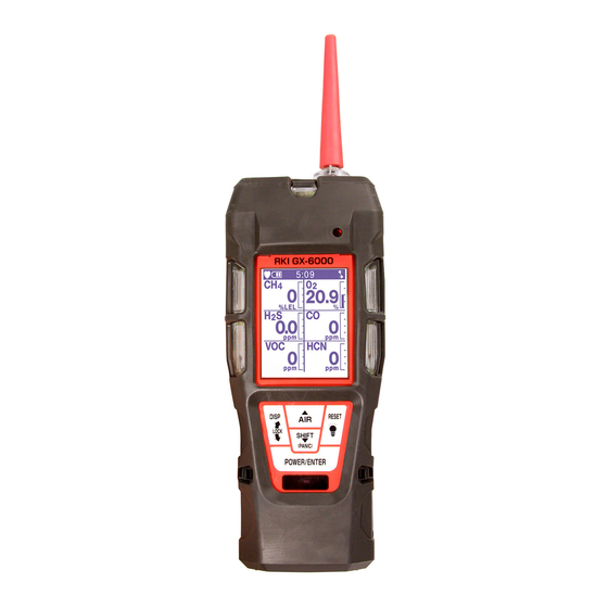
- Page 1 GX-6000 Single Sensor PID Model Operator’s Manual Part Number: 71-0363 Revision: I Released: 2/26/20 www.rkiinstruments.com...
- Page 2 Typical calibration frequencies for most applications are between 1 and 3 months, but can be required more often or less often based on your usage. GX-6000 Operator’s Manual...
-
Page 3: Table Of Contents
Turning On the GX-6000 ........ - Page 4 Viewing the ROM/SUM of the Instrument........82 GX-6000 Operator’s Manual...
- Page 5 Setting the Bar Hole Measurement Time (BAR HOLE TIME) ....132 Updating the CO Display Setting (CO DISPLAY)......132 GX-6000 Operator’s Manual...
- Page 6 Start Up ............. . 170 GX-6000 Operator’s Manual...
- Page 7 Measuring Mode ............171 Turning Off a GX-6000 with an 11.7 eV PID Sensor ..... 171 Calibrating the 11.7 eV PID Sensor .
-
Page 8: Chapter 1: Introduction
This chapter briefly describes the GX-6000 Single Sensor PID Model gas monitor. This chapter also describes the GX-6000 Single Sensor PID Model Operator’s Manual (this document). Table 1 at the end of this chapter lists the specifications for the GX-6000 Single Sensor PID Model (hereafter referred to as the GX-6000). -
Page 9: Specifications
400 ppm Factory Setting Alarm 2 10000 ppb 1000 ppm Factory Setting STEL Alarm 60.0 ppm TWA Alarm 40.0 ppm Table 2: GX-6000 Specifications Sampling Sample Draw Method Response Time T90 Within 30 Seconds Display Graphics LCD Display Operating °... -
Page 10: About This Manual
Approximately 400 g (14 oz.) About this Manual Although the GX-6000 can support up to 6 sensors, this manual specifically describes an instrument with only a PID sensor installed. The GX-6000 Single Sensor PID Model Operator’s Manual uses the following conventions for notes, cautions, and warnings. -
Page 11: Chapter 2: Description
A clear plastic window is located on the front of the case. The battery pack and flow chamber are located on the back of the GX-6000. The inlet filter holder is located on the top of the GX-6000 case. -
Page 12: Control Buttons
A computer’s infrared port or an IrDA/USB cable connected to a USB port can be used to download data saved by the GX-6000 to a computer using the GX-6000 Data Logger Management Program. See the GX-6000 Data Logger Management Program operator’s manual for data logging and downloading instructions. -
Page 13: Vibrator
GX-6000 because of flow rate reduction. Flow Chamber The flow chamber is on the back of the GX-6000 and is held in place by four Phillips screws. The flow chamber seals to the rubber sensor gasket which seals to the sensor face inside the GX-6000 and routes flow from the pump to the sensor and to the exhaust port (on the top of the GX-6000 case). -
Page 14: Inlet Filter Holder
Tapered Rubber Nozzle A cone shaped 4 inch long rubber nozzle is included with the GX-6000 as standard. It can be installed on the inlet fitting by pushing the larger end over it. The smaller end can be inserted through a hole in a wall or some other access to an enclosed area to sample the environment. -
Page 15: Rubber Boot
A red protective rubber boot can be installed over the GX-6000. Wrist Strap A wrist strap is included with the GX-6000 and can be attached to the right or left wrist strap installation feature on the GX-6000 case. Sample Hose and Probe A 3 foot sample hose with an attached probe is standard with the GX-6000. -
Page 16: Other Accessories
Align the top of the screen protector with the top of the “RKI GX-6000” logo. Press down on the center of the screen protector. Water should spread out along the entire surface of the screen protector between the screen protector and the LCD. -
Page 17: Din Rail Mounting Assembly
DIN Rail Mounting Assembly Two different DIN rail mounting assemblies are available for the GX-6000’s charger. Each assembly has two end clamps but one assembly is long enough to accommodate 1 charger and the other assembly is long enough to accommodate 4 chargers. - Page 18 Install the end clamps on the left and right side of the charger or bank of chargers to prevent sliding. DIN Rail Clamp Figure 6: Clamp Installation Figure 7: 1-Charger Installation Figure 8: 4-Charger Installation 18 • Chapter 2: Description GX-6000 Operator’s Manual...
- Page 19 Remove the clamps by pushing on the bottom of the clamp and pulling on the top of the clamp. b. Slide the charger(s) off the DIN rail. Figure 9: Charger Removal GX-6000 Operator’s Manual Chapter 2: Description • 19...
-
Page 20: Chapter 3: Operation
This chapter explains how to use the GX-6000 to perform confined space entry monitoring or general area monitoring in Normal Mode. Start Up This section explains how to start up the GX-6000, get it ready for operation, and turn it off. Turning On the GX-6000... - Page 21 • To continue accumulating peak and time-weighted average (TWA) readings (high range PID only) from the last time the GX-6000 was used, press and release the POWER/ENTER button before the countdown reaches 0 or allow the countdown to reach 0. If you do not press the POWER/ENTER button within the 5 second countdown, the GX-6000 automatically resumes accumulating the peak and TWA readings.
- Page 22 Buzzer sounds double pulsing None tone Action • Option A, Perform calibration: The GX-6000 cannot be used until • Option A, Perform calibration: a successful calibration is per- To perform a calibration, press Press and release POWER/ formed. Press and release and release POWER/ENTER.
- Page 23 Buzzer sounds double pulsing tone None tone Action • Option A, Perform bump test: The GX-6000 cannot be used until • Option A, Perform bump test: Press and release POWER/ a successful bump test has been To perform a bump test, press ENTER to perform a bump performed.
- Page 24 The Battery Voltage Screen appears for a few seconds. 4:07 BATTERY VOLTAGE 4.5V BATTERY TYPE ALKALINE LATCHING The Active Gases Screen appears for a few seconds indicating the active channel and its target gas. SMART 1 Isobutylene 10.6 eV 24 • Chapter 3: Operation GX-6000 Operator’s Manual...
- Page 25 Alarm Screen (high range PID only), and TWA Alarm Screen (high range PID only). Each screen remains on the LCD for three seconds. F.S. VOC P VOC P 6000 400.0 STEL VOC P VOC P VOC P 1000 60.0 40.0 GX-6000 Operator’s Manual Chapter 3: Operation • 25...
- Page 26 SENSOR VOC P FAIL The GX-6000 cannot be used if the PID sensor fails. Turn the instrument off and replace the sensor. 12 . The GX-6000 is now monitoring for gas in Measuring Mode. The Measuring Mode Screen appears displaying the current gas reading.
-
Page 27: Performing A Demand Zero
Continue to hold the AIR button until the LCD prompts you to release it. The GX-6000 will set the fresh air reading. Start up is complete and the unit is now ready for monitoring. If the VOC zero filter was used, remove the filter from the GX-6000’s inlet fitting or probe. -
Page 28: Measuring Mode, Normal Operation
If CONFIRMATION is set to ON in the Maintenance Mode menu (see pg.131), the GX- 6000 beeps periodically to confirm that it’s operating. Monitoring an Area Start up the GX-6000 as described above in “Start Up” on page 20. It is now in Measuring Mode. 4:07 Take the GX-6000 to the monitoring area. -
Page 29: Using Optional Sample Hoses
If a gas alarm occurs, take appropriate action. See pg.34. Using Optional Sample Hoses The standard sample hose for the GX-6000 is 3 feet long. Optional samples hoses and probes with longer hoses are available from 5 - 50 feet in 5 foot increments (see pg.110). If you are considering using a hose and probe with a longer hose, keep in mind that a longer hose will increase the GX-6000’s response time and the flowrate may decrease close to the... -
Page 30: Snap Log Mode
The third screen displays the year, month, day, and time of the snap log. The fourth screen displays the current gas reading. NOTE: If the GX-6000 detects an alarm condition while in Snap Log Mode, it will automatically exit Snap Log Mode and return to Measuring Mode. You may then reenter Snap Log Mode and take snap logs while the instrument is still in alarm. - Page 31 DISP/LOCK button. The unit will immediately return to the Measuring Mode Screen. The data recorded in Snap Log Mode can be viewed in Display Mode. See pg.52 for more information. GX-6000 Operator’s Manual Chapter 3: Operation • 31...
-
Page 32: Measuring Mode, Alarms
Alarm Indications The GX-6000 buzzer will sound an alarm, the LEDs will flash, and the vibrator will pulse when any sort of alarm condition or failure is encountered. NOTE: If an alarm condition occurs while you are in Display Mode, the GX-6000 will automatically bring up the alarm screen instead. - Page 33 The ALARM TIME defined in • Alarm LED arrays flash in circle • Vibrator pulses twice per Maintenance Mode has passed sequence twice per second second since the instrument detected movement. GX-6000 Operator’s Manual Chapter 3: Operation • 33...
-
Page 34: Responding To Alarms
LED arrays continue to flash, the below an alarm setpoint. vibrator continues to pulse, and the GX-6000 continues to display the current alarm level. • The gas reading must fall below an alarm setting before you can reset the alarm, the LEDs, and the vibrator using the RESET button. - Page 35 Take the GX-6000 to a non-hazardous area and replace or recharge the batteries as described on pg.86. The GX-6000 is fully functional during a low battery warning. However, only a limited amount of operating time remains, approximately 1 - 2 hours. The amount of time depends on how often the LCD backlight is used and how often the unit is responding to alarm conditions.
- Page 36 Attempt to change the date using the DATE menu item in Maintenance Mode. See pg.118. If the date cannot be set correctly, contact RKI Instruments, Inc. as soon as possible. Responding to System Failure Alarms If a system failure occurs, the system failure screen will display an error code as...
- Page 37 CAUTION: There will be no datalogging function if you operate the instrument after a 022 system failure. Contact RKI Instruments, Inc. as soon as possible. Responding to a Man Down Warning 1 and Warning 2 The Man Down Warning 1 and Warning 2 alarms occur after the WARNING 1 TIME and WARNING 2 TIME, respectively, has passed since the last movement of the instrument.
-
Page 38: Data Logging
Data Logging The GX-6000 features the ability to log data to its internal memory and download it to a computer via the infrared communications port on the front of the unit. It logs gas readings in Measuring Mode, alarm data, and calibration data. -
Page 39: Chapter 4: Display Mode
Chapter 4: Display Mode This section describes using the GX-6000 in Display Mode. See Table 9 below for a list of Display Mode’s menu items, a short description of each item, and the page number for further description. Table 9: Display Mode Items... -
Page 40: Pid Gas Name Screen
NOTE: With the exception of the Pump Off Screen, each screen displays for 20 seconds. If you do not press a button within 20 seconds, the GX-6000 automatically returns to Measuring Mode. If the Pump Off Screen is used to turn the instrument’s pump off, the Pump Off Screen will display until you turn... - Page 41 I s o b u t y r ic a c i d I s o d e c a n o l Use the AIR and SHIFT (PANIC) buttons to scroll through the gas names. GX-6000 Operator’s Manual Chapter 4: Display Mode • 41...
-
Page 42: Peak Screen
GX-6000 is turned off. The lunch break feature enables the GX-6000 to save the peak reading when it is turned off so it can continue them when it is turned on again. See “Turning On the GX-6000” on page 20. -
Page 43: Stel Screen
STEL Screen The STEL Screen displays the short term exposure limit (STEL) reading (high range PID only). The STEL reading is the average reading over the last 15 minutes. STEL 10.0 GX-6000 Operator’s Manual Chapter 4: Display Mode • 43... -
Page 44: Twa Screen
OFF, the TWA is cleared when the GX-6000 is turned off. If LUNCH BREAK is set to ON, the GX-6000 will remember the TWA reading when it is turned off so it can continue it when it is turned on again. See “Turning On the GX- 6000”... - Page 45 The buzzer, LED’s, and vibration will activate. Press and release the POWER/ENTER button again to stop the simulated alarm. Press and release the DISP/LOCK button to return to the View Alarm Settings Screen. GX-6000 Operator’s Manual Chapter 4: Display Mode • 45...
-
Page 46: Time In Operation Screen
The Time In Operation Screen displays the length of time since the GX-6000 was turned on if the lunch break feature is turned off. With LUNCH BREAK set to OFF, the time in operation is reset when the GX-6000 is turned off. See pg.129 for a description of the lunch break feature. -
Page 47: Log Time Remaining Screen
The LOG CLEAR screen asks if you want to clear the data logger memory. DISP LOG CLEAR YES :ENTER NO :DISP EXIT :RESET To continue through Display Mode without clearing the log data, press and release the DISP/LOCK button. GX-6000 Operator’s Manual Chapter 4: Display Mode • 47... - Page 48 The unit will display the following screen as it clears the data. DISP LOG CLEAR CLEAR When the instrument has cleared the data, it will return to the LOG CLEAR screen in Display Mode. 48 • Chapter 4: Display Mode GX-6000 Operator’s Manual...
-
Page 49: Pump Off Screen
Pump Off Screen WARNING: The GX-6000 is not a gas monitoring device while the pump is off. NOTE: The item appears in Display Mode only if the PUMP OFF DISP menu item in Maintenance Mode is turned ON. The factory setting for PUMP OFF DISP is OFF. -
Page 50: Select User Id Screen
This screen only appears in Display Mode if the ID DISPLAY item in Maintenance Mode is set to ON. Use this screen to select a user ID from the user ID list in the GX-6000’s memory. The current user ID is displayed. A user ID can be up to 16 characters long. The GX-6000 can store up to 128 user IDs. -
Page 51: Select Station Id Screen
This screen only appears in Display Mode if the ID DISPLAY item in Maintenance Mode is set to ON. Use this screen to select a station ID from the station ID list in the GX-6000’s memory. The current station ID is displayed. A station ID can be up to 16 characters long. -
Page 52: Viewing Snap Logger Data
The Snap Logging Screen allows you to view data from previous snap logs. For information on how to use the snap logging feature, see pg.30. DISP REC. DATA DISP YES :ENTER NO :DISP EXIT :RESET 52 • Chapter 4: Display Mode GX-6000 Operator’s Manual... - Page 53 To scroll through the data by viewing the snap log ID number, press and release POWER/ENTER. To return to the Snap Logging Screen, press and release the DISP/LOCK button. GX-6000 Operator’s Manual Chapter 4: Display Mode • 53...
-
Page 54: Peak Bar Screen
To return to the Peak Bar Screen without saving any changes, press and release the DISP/LOCK button. Gas Display Screen This menu item does not apply to this version of the GX-6000. LCD Flip Screen If INVERT SELECT is set to ON, the instrument’s LCD will automatically flip if the instrument is turned upside down. -
Page 55: Lcd Background Color Flip Screen
Press and release the POWER/ENTER button to return to the LCD Background Flip Screen. To return to the LCD Background Flip Screen without saving any changes, press and release the DISP/LOCK button. GX-6000 Operator’s Manual Chapter 4: Display Mode • 55... -
Page 56: Language Screen
CONFIRM ? Press and release the POWER/ENTER button again to confirm the change. To return to the Language Screen without changing the instrument’s language to English, press and release the DISP/LOCK button. 56 • Chapter 4: Display Mode GX-6000 Operator’s Manual... -
Page 57: Chapter 5: Calibration Mode
The unit should be calibrated periodically. The optimum frequency of calibration depends heavily on how the GX-6000 is used. For example, instruments used daily may need to be calibrated weekly or monthly, while instruments that are used only a few times a year may need to be calibrated before each use. -
Page 58: Entering Calibration Mode
NORMAL MODE Calibrating Using the Auto Calibration Method This method is the quickest and easiest method to calibrate the GX-6000. See Table 13 on page 110 for available cylinders. Make sure your calibration cylinder is appropriate for the PID detection range. - Page 59 To continue with the fresh air adjustment, press and hold the AIR button. If you do not want to continue, press and release the DISP/LOCK button and the unit will return to the Calibration Mode Screen. GX-6000 Operator’s Manual Chapter 5: Calibration Mode • 59...
- Page 60 AUTO CAL SINGLE CAL NORMAL MODE 10 . If the VOC zero filter was used, remove the filter from the GX-6000’s inlet fitting or probe. Reinstall the plugs on each end of the filter. 60 • Chapter 5: Calibration Mode...
-
Page 61: Performing A Span Adjustment In Auto Calibration
Install the demand flow regulator onto the calibration cylinder. Connect the sample tubing to the demand flow regulator. Install the sample hose and probe on the GX-6000 inlet fitting. Make sure the probe’s two halves are tightened firmly together to avoid leaks that can affect the calibration. - Page 62 11 . When you are done adjusting the calibration gas value, move the cursor to ESCAPE. AUTO CONCENTRATION 100.0 ppm ESCAPE 12 . Press and release the POWER/ENTER button. The instrument returns to the Auto Cal Menu. 62 • Chapter 5: Calibration Mode GX-6000 Operator’s Manual...
- Page 63 Screen in Display Mode. In the example below, acetone is the currently selected gas. If isobutylene is the selected gas, then isobutylene will appear twice in this list. AUTO GAS SELECT Isobutylene Acetone ESCAPE GX-6000 Operator’s Manual Chapter 5: Calibration Mode • 63...
- Page 64 18 . Connect the tubing from the demand flow regulator to the rigid tube on the probe. Allow the GX-6000 to draw gas for one minute. 19 . Press and release the POWER/ENTER button to set the span adjustment to the programmed value.
- Page 65 The buzzer and LEDs activate in a double pulsing pattern. Press and release POWER/ENTER to acknowledge the sensor life warning. SEN LIFE WARNING GX-6000 Operator’s Manual Chapter 5: Calibration Mode • 65...
-
Page 66: Returning To Measuring Mode
POWER/ENTER button to return to the Calibration Mode Menu. c. Use the SHIFT (PANIC) button to place the cursor next to NORMAL MODE, then press and release the POWER/ENTER button to return to Measuring Mode. 66 • Chapter 5: Calibration Mode GX-6000 Operator’s Manual... -
Page 67: Calibrating Using The Single Calibration Method
To continue with the fresh air adjustment, press and hold the AIR button. If you do not want to continue, press and release the DISP/LOCK button and the unit will return to the Calibration Mode Screen. GX-6000 Operator’s Manual Chapter 5: Calibration Mode • 67... - Page 68 The GX-6000 will indicate that it is adjusting the zero reading for a few seconds and then it will prompt you to release the AIR button. AIR CAL AIR CAL AIR CAL HOLD AIR KEY HOLD AIR KEY RELEASE AIR KEY...
-
Page 69: Performing A Span Adjustment In Single Calibration
Install the demand flow regulator onto the calibration cylinder. Connect the sample tubing to the demand flow regulator. Install the sample hose and probe on the GX-6000 inlet fitting. Make sure the probe’s two halves are tightened firmly together to avoid leaks that can affect the calibration. - Page 70 10 . Connect the tubing from the demand flow regulator to the rigid tube on the probe. Allow the GX-6000 to draw gas for one minute. 11 . If necessary, adjust the reading to match the cylinder concentration with the and SHIFT (PANIC) buttons.
- Page 71 13 . If the PID sensor is not in a sensor life warning condition or if SEN LIFE ALERT is set to OFF, the following screen sequence occurs. SINGLE SINGLE SINGLE CAL PASS ESCAPE GX-6000 Operator’s Manual Chapter 5: Calibration Mode • 71...
- Page 72 SINGLE CAL PASS ESCAPE 15 . Disconnect the tubing from the GX-6000’s probe. 16 . Unscrew the demand flow regulator from the calibration cylinder. 17 . With the Select Sensor Screen displayed, place the cursor next to ESCAPE using the AIR or SHIFT (PANIC) button.
-
Page 73: Performing A Bump Test
Install the demand flow regulator onto the calibration cylinder. Connect the sample tubing to the demand flow regulator. Install the sample hose and probe on the GX-6000 inlet fitting. Make sure the probe’s two halves are tightened firmly together to avoid leaks that can affect the calibration. - Page 74 If it is not, adjust the bump test gas value by entering the AUTO CAL menu item in Calibration Mode, changing the value there, and reentering the BUMP TEST menu item. 74 • Chapter 5: Calibration Mode GX-6000 Operator’s Manual...
- Page 75 POWER/ENTER button to return to the Gas Select Screen. See “Troubleshooting” on page 84 to investigate the cause of the failure and replace the failed sensor, if necessary. d. Disconnect the tubing from the probe. GX-6000 Operator’s Manual Chapter 5: Calibration Mode • 75...
- Page 76 The calibration time counted down during a calibration initiated because of a failed bump test is the difference between the gas time and the calibration time defined in the BUMP SETTING menu item in Maintenance Mode. 60CAL 100.0 76 • Chapter 5: Calibration Mode GX-6000 Operator’s Manual...
- Page 77 POWER/ENTER button to return to the Calibration Mode Menu. 15 . Use the SHIFT (PANIC) button to place the cursor next to the NORMAL MODE menu option, then press and release the POWER/ENTER button to return to Measuring Mode. GX-6000 Operator’s Manual Chapter 5: Calibration Mode • 77...
-
Page 78: Chapter 6: User Mode
Chapter 6: User Mode Overview This section describes the GX-6000 in User Mode. See Table 10 below for a list of the items found in User Mode, the page that the menu item’s instructions can be found on, and a short description of the menu item. -
Page 79: Entering User Mode
Entering User Mode WARNING: The GX-6000 is not in operation as a gas detector while in User Mode. Take the GX-6000 to a non-hazardous location and turn it off if it is on. Press and hold the AIR and SHIFT (PANIC) buttons, then press and hold the POWER/ENTER button. -
Page 80: Setting The Date And Time
Press and release POWER/ENTER to save the setting. The month setting flashes. Repeat Step 3 and Step 4 to enter the month, day, hours, and minutes settings. The main menu displays after you enter the seconds setting. 80 • Chapter 6: User Mode GX-6000 Operator’s Manual... -
Page 81: Setting The Date Format
This menu item does not apply to this version of the GX-6000. Updating the Language Setting The LANGUAGE menu item allows you to select the language for the GX-6000’s user interface. The available choices are English (factory setting), Japanese, Italian, Spanish, German, French, Portuguese, Russian, and Korean. -
Page 82: Viewing The Rom/Sum Of The Instrument
Press and release the POWER/ENTER button again to return to the main menu. Turning the Password Function On or Off With PASSWORD set to ON, the GX-6000 prompts you for a password when you enter User Mode and Calibration Mode. -
Page 83: Exiting User Mode
Exiting User Mode From the main menu, place the cursor in front of START MEASURE at the bottom of the menu. Press and release POWER/ENTER. The unit will begin its start-up sequence. GX-6000 Operator’s Manual Chapter 6: User Mode • 83... -
Page 84: Chapter 7: Maintenance
Chapter 7: Maintenance Overview This chapter describes troubleshooting procedures for the GX-6000. It also includes procedures for replacing and recharging the batteries and replacing various consumable parts. WARNING: RKI Instruments, Inc. recommends that service, calibration, and repair of RKI Instruments be performed by personnel properly trained for this work. - Page 85 (auto calibration 2. Make sure the GX-6000 has been only). properly set up for calibration. 3. Verify that the calibration cylinder • The sample gas is not reaching...
-
Page 86: Replacing Or Recharging The Batteries
WARNING: Do not remove the batteries while the GX-6000 is on. Turn the GX-6000 over so that the flow chamber and battery cover are facing up and the LCD is facing down. Push the battery cover latch toward the bottom of the instrument. - Page 87 Carefully install the new AA alkaline batteries according to the battery diagram inside the battery compartment. Figure 12: Installing the Alkaline Batteries Close the battery cover and secure the battery cover latch by pushing it up and toward the top of the instrument. GX-6000 Operator’s Manual Chapter 7: Maintenance • 87...
-
Page 88: Replacing The Lithium Ion Battery Pack
Do not remove the battery pack while the GX-6000 is on. Remove the rubber boot, if installed. Turn the GX-6000 over so that the flow chamber and battery cover are facing up and the LCD is facing down. The battery pack release latch is located on the bottom of the instrument and is closer to the front of the case than the back. -
Page 89: Recharging The Lithium Ion Battery Pack
RKI charger model BC-6000, p/n 49-2182, or RKI charger model BC- 6000DC, p/n 49-2183. Use of other rechargeable batteries or chargers or charging of other rechargeable batteries in the GX-6000 will void the warranty. PRUDENCE: Pour être utilisé uniquement avec une batterie au lithium-ion p/n 49-1619. - Page 90 One adapter will not operate more than one charging station. Place the GX-6000 into the battery charging station as shown in Figure 17 below so that the metal contacts on the back of the unit come into contact with the metal contacts on the back of the holder in the charging station.
-
Page 91: Recharging The Lithium Ion Battery Pack Out Of The Instrument
The lithium ion battery pack may be charged using the charging station while it is out of the GX-6000. This is useful if spare battery packs are kept in case the pack in the GX- 6000 needs to be charged, but the unit must be used immediately. In this case, a spare charged pack can be installed in the GX-6000 and the dead pack charged in the charging station. - Page 92 One adapter will not operate more than one charging station. If necessary, remove the battery pack from the instrument as described in Step 1 - Step 6 on pg.88. 92 • Chapter 7: Maintenance GX-6000 Operator’s Manual...
- Page 93 Remove the battery pack from the charging station and unplug the charging station’s power cord from the AC outlet. If necessary, reinstall the battery pack as described in Step 7 - Step 8 on pg.88. GX-6000 Operator’s Manual Chapter 7: Maintenance • 93...
-
Page 94: Replacing The Probe's Particle Filter And Hydrophobic Filter Disk
Replacing the Probe’s Particle Filter and Hydrophobic Filter Disk Inspect the probe’s internal components if you notice that the GX-6000’s pump sounds bogged down or if an unexplained low flow alarm occurs. Replace the particle filter and hydrophobic filter disk if they appear dirty or saturated with liquid. Replace the gasket in the probe if it appears damaged. -
Page 95: Replacing The Pid Sensor
Verify that the GX-6000 is off. Use a small Phillips screwdriver to unscrew the four screws holding the flow chamber to the rest of the GX-6000’s case. Grasp the sides of the flow chamber and lift it away from the rest of the case. The screws are captive screws and will not come out of the flow chamber. - Page 96 The flow fitting connections need to be facing up and cannot be skewed sideways. The gasket must be pushed down in the center and secured under the gasket aligning tabs. 96 • Chapter 7: Maintenance GX-6000 Operator’s Manual...
- Page 97 12 . To verify that the sensor gasket was inserted properly: a. Plug the inlet with your finger. b. Verify that the GX-6000 goes into low flow alarm. If the GX-6000 does not go into low flow alarm, turn the instrument off and attempt to seat the sensor gasket again.
-
Page 98: Replacing The Hydrophobic Filter And Wire Mesh Disk
Replacing the Hydrophobic Filter and Wire Mesh Disk Verify that the GX-6000 is off. Locate the clear plastic filter holder at the top of the GX-6000. Grasp the filter holder and turn it 1/4 turn counterclockwise. 4. Pull the filter holder away from the case. -
Page 99: Pid Sensor Maintenance
Verify that the GX-6000 is off. Use a small Phillips screwdriver to unscrew the four screws holding the flow chamber to the rest of the GX-6000’s case. Grasp the sides of the flow chamber and lift it away from the rest of the case. The screws are captive screws and will not come out of the flow chamber. - Page 100 11 . Hold the lamp in one hand being careful not to touch the lamp window with your fingers. 12 . With the other hand collect a small amount of aluminum oxide powder on a cotton swab. 100 • Chapter 7: Maintenance GX-6000 Operator’s Manual...
- Page 101 17 . Hold the electrode stack between the thumb and forefinger of one hand and place the window end of the lamp inside the O-ring seal in the electrode stack with the other hand as shown below. Figure 28: Reinstalling the Electrode Lamp GX-6000 Operator’s Manual Chapter 7: Maintenance • 101...
- Page 102 25 . Insert the flow chamber back into the instrument. 26 . Tighten the flow chamber’s four screws that were loosened in Step 2. 27 . Start up the GX-6000 by pressing and briefly holding the POWER/ENTER button. 102 • Chapter 7: Maintenance...
-
Page 103: Replacing The Pid Sensor's Lamp
28 . To verify that the sensor gasket was inserted properly: a. Plug the inlet with your finger. b. Verify that the GX-6000 goes into low flow alarm. If the GX-6000 does not go into low flow alarm, turn the instrument off and attempt to seat the sensor gasket again. - Page 104 11 . Discard the old PID lamp. NOTE: At this point it is recommended that the finger cots be used on the fingers handling the lamp. Finger cots are included with the lamp cleaning kit. 104 • Chapter 7: Maintenance GX-6000 Operator’s Manual...
- Page 105 The gasket must be pushed down in the center and secured under the gasket aligning tabs. Failure to install the sensor gasket appropriately may result in inaccurate gas readings. GX-6000 Operator’s Manual Chapter 7: Maintenance • 105...
-
Page 106: Replacing The Pid Sensor's Electrode Stack
24 . Calibrate the PID sensor as described in “Chapter 5: Calibration Mode” on page 57. Replacing the PID Sensor’s Electrode Stack The electrode stack can last for the life of the PID sensor if the GX-6000 is used in a very clean, controlled environment. When used in a heavily contaminated or dirty environment, the electrode stack may only last a month. - Page 107 10 . If the spring in the lamp cavity comes out, place it back into the lamp cavity. 11 . Discard the old electrode stack. GX-6000 Operator’s Manual Chapter 7: Maintenance • 107...
- Page 108 The flow fitting connections need to be facing up and cannot be skewed sideways. The gasket must be pushed down in the center and secured under the gasket aligning tabs. 108 • Chapter 7: Maintenance GX-6000 Operator’s Manual...
- Page 109 23 . To verify that the sensor gasket was inserted properly: a. Plug the inlet with your finger. b. Verify that the GX-6000 goes into low flow alarm. If the GX-6000 does not go into low flow alarm, turn the instrument off and attempt to seat the sensor gasket again.
-
Page 110: Chapter 8: General Parts List
USB/IrDA adapter with cable and CD (not for use with Eagle 2) 49-0115RK AC adapter 49-1120RK AA size alkaline battery 49-1619 Li-ion battery pack 49-1620 Alkaline battery pack 49-2182-01 Battery charger, BC-6000, with 100 - 240 VAC adapter 110 • Chapter 8: General Parts List GX-6000 Operator’s Manual... - Page 111 Sample hose with integral probe, with hydrophobic filter and particle filter, no scrubber section. Replace “XX” with length in feet. 3 foot hose is standard. Available lengths for the GX-6000 are 3, 5, 10, 15, 20, 25, 30, 35, 40, 45, and 50 feet. 80-0172...
-
Page 112: Appendix A: Maintenance Mode
Appendix A: Maintenance Mode Overview This appendix describes the GX-6000 in Maintenance Mode. The GX-6000 is factory-set to suit most applications. Update settings in Maintenance Mode only if required for your specific application. Maintenance Mode items and their factory settings are listed in Table 14 below. - Page 113 OFF - 255 SEC 30 SEC LANGUAGE (pg.129) • ENGLISH ENGLISH • JAPANESE • ITALIAN • SPANISH • GERMAN • FRENCH • PORTUGUESE • RUSSIAN • KOREAN LUNCH BREAK (pg.129) • ON • OFF GX-6000 Operator’s Manual Appendix A: Maintenance Mode • 113...
- Page 114 • 60 SEC • 120 SEC • 180 SEC • 300 SEC • 600 SEC LOG CLEAR DISP (pg.134) • ON • OFF LOG OVER WRITE (pg.135) • ON • OFF 114 • Appendix A: Maintenance Mode GX-6000 Operator’s Manual...
-
Page 115: Entering Maintenance Mode
WARNING: The GX-6000 is not in operation as a gas detector while in Maintenance Mode. Take the GX-6000 to a non-hazardous location and turn it off if it is on. Press and hold the AIR and SHIFT (PANIC) buttons, then press and hold the POWER/ENTER button. - Page 116 ENTER button to enter Maintenance Mode. There is no need to enter a password. The password screen appears even if PASSWORD is set to OFF so that a special factory mode can be accessed, if necessary. 116 • Appendix A: Maintenance Mode GX-6000 Operator’s Manual...
-
Page 117: Tips For Using Maintenance Mode
Press the DISP/LOCK button while in a screen where you are entering or updating parameters to exit the screen without saving any changes. You can also use the DISP/ LOCK button to back out of submenus and return to the main menu. GX-6000 Operator’s Manual Appendix A: Maintenance Mode • 117... -
Page 118: Setting The Date And Time (Date)
Press and release POWER/ENTER. The Date Format screen appears with the current setting displayed. AIR or SHIFT (PANIC) to display the desired setting. Press and release POWER/ENTER to save the setting and return to the main menu. 118 • Appendix A: Maintenance Mode GX-6000 Operator’s Manual... -
Page 119: Performing A Calibration (Gas Calibration)
BUMP TEST menu item will not appear unless BUMP DISP is set to ON. See pg.122 for instructions. Entering the BUMP TEST menu item brings you to the first of the Gas Select Screens. See pg.73 for instructions, starting at Step 8. GX-6000 Operator’s Manual Appendix A: Maintenance Mode • 119... -
Page 120: Updating Calibration Settings (Cal Setting)
The type of indication will depend on the CAL EXPRD setting (see pg.121). With CAL REMINDER set to OFF, the GX-6000 will not give an indication at start up if it is due for calibration. - Page 121 Press and release DISP/LOCK to continue without calibrating or POWER/ENTER to perform a calibration. With CAL EXPRD set to CANNOT USE, if the unit is due for calibration, the GX-6000 will give an indication at start up that calibration is past due and will prompt you to press and release POWER/ENTER to enter Calibration Mode and perform a calibration.
-
Page 122: Updating Bump Test Settings (Bump Setting)
Mode. RKI Instruments, Inc. recommends setting BUMP DISP to ON if BUMP REMINDER is also set to ON. NOTE: BUMP DISP must be set to ON to have the GX-6000’s bump test date reset after a successful bump test in an SDM-6000. - Page 123 For example, if the CAL TIME is set to 90 seconds and the GAS TIME is set to 30 seconds, if the bump test fails, the GX-6000 will only be exposed to gas for an additional 60 seconds. The available values are 90 seconds (factory setting), and 120 seconds.
- Page 124 Updating the Bump Reminder Setting (BUMP REMINDER) With BUMP REMINDER set to ON, the GX-6000 will give an indication at start up if it is due for bump testing. The type of indication will depend on the BUMP EXPRD setting (see pg.125).
- Page 125 BUMP SETTING screen. Updating the Bump Check Gas Setting (BUMP CHECK GAS) For this version of the GX-6000, the BUMP CHECK GAS parameter needs to be set to ALL GAS. It is not recommended that this parameter be changed.
-
Page 126: Updating Alarm Parameters (Alarm Setting)
Updating the Alarm Point Settings (ALARM POINTS) This menu item allows you to update one or more alarm points (the reading at which the GX-6000 recognizes the alarm condition). See Table 1 on page 9 for alarm point factory settings. - Page 127 With ALARM SILENCE set to ON (factory setting), pressing and releasing the RESET button silences the buzzer when the GX-6000 is in alarm. The LEDs continue to flash, the vibrator continues to pulse, and the display continues to show the alarm. If you enter Display Mode during an alarm condition, the buzzer will be silenced but the LEDs will continue to flash and the vibrator will continue to pulse.
-
Page 128: Turning The Pump On/Off Display On Or Off (Pump Off Disp)
This setting indicates the length of time the LCD illuminates when you press any button. The minimum setting is OFF; the maximum setting is 255 seconds. The factory setting is 30 seconds. From the main menu, place the cursor next to BACK LIGHT TIME. 128 • Appendix A: Maintenance Mode GX-6000 Operator’s Manual... -
Page 129: Updating The Language Setting (Language)
With LUNCH BREAK set to ON, the Lunch Break Screen displays during startup. From this screen, you can choose to continue accumulating TWA and PEAK readings and the time in operation from the last time the GX-6000 was used or start collecting new readings and reset the time in operation. -
Page 130: Updating The Auto Zero Setting (Auto Zero)
Updating the Auto Zero Setting (AUTO ZERO) This setting allows you to configure the GX-6000 so that a fresh air adjustment takes place automatically as part of the instrument startup sequence. If AUTO ZERO is set to ON, the GX-6000 performs a fresh air adjustment at the end of the startup sequence before entering Measuring Mode. -
Page 131: Updating The Confirmation Alert Setting (Confirmation)
CONFIRMATION to ON. The interval can be 1 - 60 minutes. The factory setting is 5 minutes. With CONFIRMATION set to OFF (factory setting), the GX-6000 does not provide a confirmation alert. From the main menu, place the cursor next to CONFIRMATION. -
Page 132: Turning Inert Mode On Or Off (Inert Mode)
Turning Inert Mode On or Off (INERT MODE) This menu item does not apply to this version of the GX-6000. Updating the Leak Check/Bar Hole Mode Setting (L./B. MODE) This menu item does not apply to this version of the GX-6000. - Page 133 The factory setting is 90 seconds. When setting the ALARM TIME, keep in mind that ALARM TIME WARNING 2 TIME WARNING 1 TIME. From the MAN DOWN MENU screen, place the cursor next to ALARM TIME. Press and release POWER/ENTER. The Alarm Time Screen appears. GX-6000 Operator’s Manual Appendix A: Maintenance Mode • 133...
-
Page 134: Updating The Datalogging Parameters (Log Setting)
Press and release POWER/ENTER. The LOG SETTING menu appears. Updating the Data Log Interval Setting (LOG INTERVAL) This setting indicates how often the GX-6000 saves the gas reading to the data logger. The following interval times can be selected: 10 minutes, 5 minutes (factory setting), 3 minutes, 2 minutes, 1 minute, 30 seconds, 20 seconds, or 10 seconds. - Page 135 With LOG OVER WRITE set to ON (factory setting), the GX-6000 writes over the oldest data with new data when the data logger memory is full. With LOG OVER WRITE set to OFF, the GX-6000 stops saving data to the data logger when the data logger memory is full.
-
Page 136: Adjusting The Low Flow Setpoint (Flow Adjust)
Connect a flow meter with a valve to the inlet of the instrument and adjust it to 0.2 LPM ± 0.1 LPM. This will be the low flow setpoint. You do not need to adjust anything at the instrument. 136 • Appendix A: Maintenance Mode GX-6000 Operator’s Manual... -
Page 137: Viewing The Rom/Sum Of The Instrument (Rom/Sum)
Press and release the POWER/ENTER button again to return to the main menu. Turning the Password Function On or Off (PASSWORD) With PASSWORD set to ON (factory setting), the GX-6000 prompts you for a password when you enter Maintenance Mode. The factory set password is 0006. -
Page 138: Restoring The Default Settings (Restore Default)
Maintenance Mode, the default settings are the same as the standard factory settings. If you want to return the GX-6000 to its default configuration, it is possible to do so by using the Default Settings menu item in Maintenance Mode. Returning the GX-6000 to its... -
Page 139: Exiting Maintenance Mode (Start Measure)
Exiting Maintenance Mode (START MEASURE) From the main menu, place the cursor in front of START MEASURE at the bottom of the menu. Press and release POWER/ENTER. The unit will begin its start-up sequence. GX-6000 Operator’s Manual Appendix A: Maintenance Mode • 139... -
Page 140: Appendix B: Maintenance Mode 2
WARNING: The GX-6000 is not in operation as a gas detector while in Maintenance Mode 2. Take the GX-6000 to a non-hazardous location and turn it off if it is on. Press and hold the AIR and SHIFT (PANIC) buttons, then press and hold the POWER/ENTER button. - Page 141 The password for Maintenance Mode 2 is 2014. If you enter an incorrect password, an error screen will appear. PASSWORD PASSWORD ERROR You must turn the unit off and reenter Maintenance Mode 2 using the correct password. GX-6000 Operator’s Manual Appendix B: Maintenance Mode 2 • 141...
-
Page 142: Tips For Using Maintenance Mode 2
Changing the Catalytic LEL Channel’s Target Gas (HC SELECT) The HC SELECT menu item allows you to change the catalytic LEL channel’s target gas. This menu item is not used in this version of the GX-6000. 142 • Appendix B: Maintenance Mode 2 GX-6000 Operator’s Manual... -
Page 143: Changing The Streaming Setting (Streaming Mode)
Changing the Streaming Setting (STREAMING MODE) With STREAMING MODE set to ON, the GX-6000 streams real-time data from the IrDA port. Contact RKI Instruments, Inc. to obtain document 71-0486 and to get more information about Streaming Mode. With STREAMING MODE set to OFF (factory setting), the GX-6000 does not stream real-time data from the IrDA port. -
Page 144: Appendix C: 10.0 Ev/Benzene Pid Sensor
Mode. Even though the 10.0 eV/benzene sensor can be used for general VOC detection, if your application is for general VOC detection and is not related to monitoring for benzene specifically, RKI Instruments, Inc. recommends that the low range or high range 10.6 eV PID sensor be used instead. -
Page 145: Sensor Description
It is installed in a white housing that has three sockets on the bottom that mate with the GX-6000 instrument. The PID sensor must always be installed in the first smart sensor position which is located in the top left corner of the sensor block. -
Page 146: Start Up
Start Up The instructions for starting up a GX-6000 with a 10.0 eV/benzene PID sensor installed are the same as described in “Start Up” on page 20 with the exception of the screens shown in Step 8. Those screens appear as shown below. -
Page 147: Measuring Mode
WARNING: If you take the GX-6000 to an area that is 10 or 15 degrees different than the previous area, allow the instrument 45 minutes to acclimate before taking any readings. Failure to do so may cause the reading to be inaccurate. - Page 148 You will be prompted to start a benzene measurement. TUBE START MEASUREMENT YES :ENTER NO :DISP Press and release the POWER/ENTER button to start the benzene measurement. 148 • Appendix C: 10.0 eV/Benzene PID Sensor GX-6000 Operator’s Manual...
- Page 149 YES :ENTER NO :DISP 43SEC • Press the POWER/ENTER button to confirm the measurement cancel. • Press the DISP/LOCK button to return to the measuring screen without canceling the measurement. GX-6000 Operator’s Manual Appendix C: 10.0 eV/Benzene PID Sensor • 149...
- Page 150 11 . To start another measurement, press and release the POWER/ENTER button. WARNING: If you take the GX-6000 to an area that is 10 or 15 degrees different than the previous area, allow the instrument 45 minutes to acclimate before taking any readings. Failure to do so may cause the reading to be inaccurate.
- Page 151 TUBE REMOVE HOLDER YES :ENTER NO :DISP b. Remove the tube holder from the GX-6000’s inlet fitting. c. Press and release the POWER/ENTER button. 13 . To proceed with taking a STEL measurement, press and release the RESET button. TUBE...
- Page 152 At the end of the STEL countdown, the STEL reading displays. TUBE BNZ STEL 0.00 REPEAT ? YES :ENTER NO :DISP f. To repeat the STEL measurement, press and release POWER/ENTER. 152 • Appendix C: 10.0 eV/Benzene PID Sensor GX-6000 Operator’s Manual...
-
Page 153: Viewing Benzene Select Mode Data
REMOVE HOLDER YES :ENTER NO :DISP h. Remove the tube holder from the GX-6000’s inlet fitting. i. Press and release the POWER/ENTER button. Viewing Benzene Select Mode Data Readings taken in Benzene Select Mode are saved to the snap logger. To view Benzene... - Page 154 The last line of the screen indicates the Station ID that was used for the snap log. Use the AIR and SHIFT (PANIC) buttons to scroll through different snap log IDs. 154 • Appendix C: 10.0 eV/Benzene PID Sensor GX-6000 Operator’s Manual...
- Page 155 Select Mode 3:45 Standard Data ENTER BENZENE SELECT NUMBER TANK 5 SHIFT SHIFT REC DATA REC DATA DATE 5/20/2015 MM/DD/YYYY Measuring POWER/ 3:40 Mode ENTER Data NUMBER TANK 5 GX-6000 Operator’s Manual Appendix C: 10.0 eV/Benzene PID Sensor • 155...
-
Page 156: Calibrating The 10.0 Ev/Benzene Pid Sensor
AUTO CAL or SINGLE CAL with isobutylene (or other target gas)** detection* * Even though it is possible to use the 10.0 eV/benzene PID sensor for general VOC detection, RKI Instruments, Inc. recommends using the low range or high range 10.6 eV sensor instead. -
Page 157: Performing An Auto Cal
TUBE CAL operation using one of the tubes from the new box. WARNING: If you take the GX-6000 to an area that is 10 or 15 degrees different than the previous area, allow the instrument 45 minutes to acclimate before taking any readings. - Page 158 Press and release the POWER/ENTER button to enter the TUBE CAL Menu. TUBE CAL GAS CALIBRATION AUTO CAL SINGLE CAL ESCAPE Use the SHIFT (PANIC) button to place the cursor next to AUTO CAL. 158 • Appendix C: 10.0 eV/Benzene PID Sensor GX-6000 Operator’s Manual...
- Page 159 11 . Attach the other end of the calibration tubing to the tube holder’s inlet fitting. 12 . Use the SHIFT (PANIC) button to place the cursor next to START CAL. GX-6000 Operator’s Manual Appendix C: 10.0 eV/Benzene PID Sensor • 159...
- Page 160 Auto Calibration Menu. See “Troubleshooting” on page 84. 16 . Use the SHIFT (PANIC) button to place the cursor next to ESCAPE, then press and release the POWER/ENTER button to return to the TUBE CAL Menu. 160 • Appendix C: 10.0 eV/Benzene PID Sensor GX-6000 Operator’s Manual...
- Page 161 TUBE CAL REMOVE HOLDER YES :ENTER NO :DISP 18 . Remove the tube holder from the GX-6000’s inlet fitting. 19 . Press and release the POWER/ENTER button. You will return to the Calibration Mode Menu. 20 . Use the SHIFT...
- Page 162 Attach the other end of the calibration tubing to the tube holder’s inlet fitting. Use the SHIFT (PANIC) button to place the cursor next to SINGLE CAL. 10 . Press and release the POWER/ENTER button. 162 • Appendix C: 10.0 eV/Benzene PID Sensor GX-6000 Operator’s Manual...
- Page 163 TUBE CAL REMOVE HOLDER YES :ENTER NO :DISP 16 . Remove the tube holder from the GX-6000’s inlet fitting. 17 . Press and release the POWER/ENTER button. You will return to the Calibration Mode Menu. 18 . Use the SHIFT...
-
Page 164: Entering A Cal Code
AIR CAL AUTO CAL SINGLE CAL TUBE CAL CAL CODE ESCAPE Use the SHIFT (PANIC) button to place the cursor next to CAL CODE. Press and release the POWER/ENTER button. 164 • Appendix C: 10.0 eV/Benzene PID Sensor GX-6000 Operator’s Manual... -
Page 165: Maintenance
“3/4” line (into the side without the text and arrow), the tube needs to be replaced. Even though discoloration can be a measure of when to replace the tube, not all gases cause the filter material to discolor which is why RKI Instruments, Inc. recommends GX-6000 Operator’s Manual... - Page 166 Line up the locking feature in the front half with its mate in the back half and insert the front half/tube assembly into the back half making sure the locking feature engages. Back Half Tube Front Half Locking Feature Figure 39: Reassembling Tube Holder 166 • Appendix C: 10.0 eV/Benzene PID Sensor GX-6000 Operator’s Manual...
-
Page 167: Parts List
82-0300RK Aluminum oxide powder PID lamp cleaning kit, with electrode stack removal tool, for 10.0 eV and 10.6 eV PID sensors’ lamps ONLY PID-003L PID sensor, 10.0 eV/benzene GX-6000 Operator’s Manual Appendix C: 10.0 eV/Benzene PID Sensor • 167... -
Page 168: Appendix D: 11.7 Ev Pid Sensor
The PID-004 11.7 eV PID sensor’s lamp (RKI P/N 51-1504) is susceptible to humidity and its service life is not as long as lamps in other PID sensors sold by RKI Instruments, Inc. For this reason, the PID-004 11.7 eV sensor’s lamp is warranted for 2 months from the date of shipment. -
Page 169: Description
Description Instrument A GX-6000 that contains an 11.7 eV PID sensor is shipped with a black rubber cap plugging the inlet fitting. This rubber cap helps prolong the life of the 11.7 eV PID sensor by preventing ambient moisture from entering the flow system. This rubber cap should be installed back onto the inlet fitting before storing the GX-6000. -
Page 170: Start Up
Start Up The instructions for starting up a GX-6000 with a 11.7 eV PID sensor installed are the same as described in “Start Up” on page 20 with the following exceptions: • Remove the black cap from the inlet fitting before turning on the instrument. -
Page 171: Measuring Mode
Eliminating as much moisture from the flow system as possible before turning off the GX-6000 will help prolong the life of the 11.7 eV PID sensor’s lamp. Remove the tubing from one end of the dehumidifier filter. It does not matter which end you remove. -
Page 172: Calibrating The 11.7 Ev Pid Sensor
See “Calibrating Using the Auto Calibration Method” for instructions to perform an automatic calibration while keeping the following in mind: • When turning off the GX-6000 after performing a calibration, follow the instructions on pg.171. Performing a SINGLE CAL See pg.67 for instructions to perform a single calibration while keeping the following in mind: •... -
Page 173: Cleaning The 11.7 Ev Pid Sensor's Lamp
Using the anhydrous methanol more than 3 months after opening it or after the cap has been off for an extended period of time may damage the 11.7 eV lamp. GX-6000 Operator’s Manual Appendix D: 11.7 eV PID Sensor • 173... -
Page 174: Parts List For 11.7 Ev Pid Instruments
Parts List for 11.7 eV PID Instruments Table 19: Spare Parts List for 11.7 eV PID Instruments Part Number Description 07-0220 Rubber cap, black, for dehumidifier filter and GX-6000 inlet fitting 33-0564 PID sensor electrode stack, 11.7 eV sensor 33-2125-01 Dehumidifier filter with tubing 51-1504 PID sensor replacement lamp, 11.7 eV sensor... -
Page 175: Appendix E: Creating A Pid User List
Appendix E: Creating a PID User List Overview This appendix explains how to set up a User List for the GX-6000’s PID sensor(s). This User List appears in the PID Gas Name Screen in the GX-6000’s Display Mode. The PID User List is not related to the GX-6000’s User ID list. -
Page 176: Editing The User List
Select the gas in the Complete Gas List. b. Click Add. To remove a gas from the PID User List: a. Select the gas in the PID User List. b. Click Remove. 176 • Appendix E: Creating a PID User List GX-6000 Operator’s Manual... - Page 177 (10.6 eV, 10.0 eV, or 11.7 eV), each PID User List must be saved separately. Click Upload to save the PID User List to the GX-6000. If necessary, repeat Step 3 - Step 8 to edit the PID User Lists for the other PID sensor types (10.6 eV, 10.0 eV, or 11.7 eV).
- Page 178 Warranty RKI Instruments, Inc. warrants the GX-6000 sold by us to be free from defects in materials, workmanship, and performance for a period of two years from the date of shipment from RKI Instruments, Inc. This includes the instrument and the original sensors.
Need help?
Do you have a question about the GX-6000 and is the answer not in the manual?
Questions and answers