
Related Manuals for Intel E42249-003


Summary of Contents for Intel E42249-003
- Page 1 ® Intel Server Board S5500BC Technical Product Specification Intel order number: E42249-003 Revision 1.0 January, 2009 Enterprise Platforms and Services Division - Marketing...
- Page 2 Intel disclaims any express or implied warranty, relating to sale and/or use of Intel products including liability or warranties relating to fitness for a particular purpose, merchantability, or infringement of any patent, copyright or other intellectual property right.
-
Page 3: Table Of Contents
Independent Channel Mode .................. 27 3.2.8 Channel Mirroring Mode ..................27 3.2.9 Lockstep Channel Mode ..................27 3.2.10 Demand and Patrol Scrub ..................28 ® Intel I/O Hub (IOH) 5500 chipset................28 3.3.1 PCI Express* Gen 2....................29 Intel order number: E42249-003 Revision 1.0... - Page 4 3.3.3 Controller Link (M-Link) ..................29 3.3.4 Management Engine (ME) ..................29 3.3.5 Intel ® Virtualization Technology for Directed I/O (Intel ® VT-d) (rev. 2)....30 Intel ® 82801Jx I/O Controller Hub (ICH10R)............31 3.4.1 PCI and PCI Express* Interfaces................31 3.4.2...
- Page 5 Serial Port Connectors................... 58 5.6.4 USB and GigE Connector..................58 Fan Headers ......................60 SGPIO Header....................... 61 Chassis Intrusion Header ..................61 5.10 SMB Hot-Swap Backplane (HSBP) Header............61 5.11 SATA RAID Key Header ..................62 Intel order number: E42249-003 Revision 1.0...
- Page 6 Certifications / Registrations / Declarations ............77 9.1.4 Product Ecology Requirements ................77 Product Regulatory Compliance Markings ............79 Electromagnetic Compatibility Notices ..............81 9.3.1 FCC Verification Statement (USA) ................ 81 9.3.2 ICES-003 (Canada) ....................82 Revision 1.0 Intel order number: E42249-003...
- Page 7 Appendix C: POST Error Messages and Handling ..............94 Appendix D: POST Code Diagnostic LED Decoder ............... 99 ® Appendix E: Intel Server System SR1630BC..............103 ® Appendix F: Supported Intel Server Chassis SC5650............104 Glossary........................... 105 Reference Documents ......................108 viii Intel order number: E42249-003 Revision 1.0...
- Page 8 Figure 11. External I/O Layout................14 Figure 12. Functional Block Diagram............... 15 ® ® Figure 13. Intel IOH 5500 Chipset with Intel QuickPath Interconnect Block Diagram ........................17 Figure 14. ILM backplate and URS................22 Figure 15. DIMM Organization................. 23 ...
- Page 9 Table 29. Jumper Block Matrix ................63 Table 30. System Status LED Indicator States............66 Table 31. DIMM LEDs Indicator States ..............67 Table 32. Fan LED Indicator States................. 67 Intel order number: E42249-003 Revision 1.0...
- Page 10 Table 42. POST Error Messages and Handling ............94 Table 43. POST Error Beep Codes ................. 97 Table 44. POST Progress Code LED Example ............99 Table 45. Diagnostic LED POST Code Decoder ........... 100 Revision 1.0 Intel order number: E42249-003...
- Page 11 ® List of Tables Intel Server Board S5500BC TPS < This page intentionally left blank. > Intel order number: E42249-003 Revision 1.0...
-
Page 12: Introduction
Intel Server Boards support add-in peripherals and contain high-density VLSI and power delivery components that need adequate airflow to cool. Intel ensures through its own chassis development and testing that when Intel server building blocks are used together, the fully integrated system will meet the intended thermal requirements of these components. -
Page 13: Product Overview
Feature Description ® ® ® Processors LGA 1366 sockets supporting up to two Intel Xeon processor 5500 series with Intel QuickPath Interconnect (QPI) and Integrated Memory controllers. Memory Eight DDR3 DIMM slots supporting DDR3 800/1066/1333 MT/s ECC Registered DIMM and ECC or Non-ECC unbuffered DIMM. Four slots support CPU_1 and four slots support CPU_2. - Page 14 Intel IOH 5500 chipset. One 82567 Gigabit Network Connection that connects to the Gigabit LAN ® Connect Interface / LAN Connect Interface on the Intel ICH10R Two 10/100/1000 Base-TX Interfaces through RJ-45 connectors with integrated magnetics.
-
Page 15: Server Board Layout
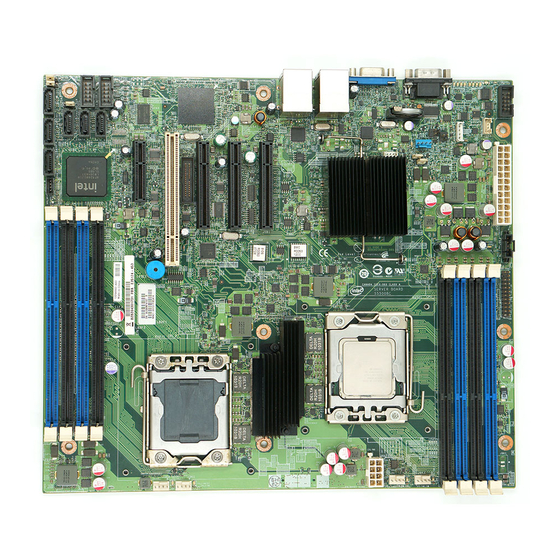
Server Board Connector and Component Layout Figure 2 shows the board layout of the server board. Each connector and major component is identified by a number or letter, and a description is below the figure. Intel order number: E42249-003 Revision 1.0... -
Page 16: Figure 2. Intel
DIMM sockets for Channel A & B (Supports CPU_1) Power Supply Auxiliary Connector SSI 24 pin Front Panel connector System fan 2 header CPU_1 fan header CPU Power Connector ® CPU_1 Socket Intel IOH 5500 chipset Revision 1.0 Intel order number: E42249-003... -
Page 17: Server Board Mechanical Drawing
System fan 1 header DIMM sockets for Channel D and E (Supports CPU_2) SATA SGPIO SATA 0 SATA 1 SATA 2 2.2.2 Server Board Mechanical Drawing Figure 3. Key Connector and LED Indicator Identification Intel order number: E42249-003 Revision 1.0... -
Page 18: Figure 4. Mounting Hole Location
® Intel Server Board S5500BC TPS Product Overview Figure 4. Mounting hole location Revision 1.0 Intel order number: E42249-003... -
Page 19: Figure 5. Major Connector Pin-1 Locations
® Product Overview Intel Server Board S5500BC TPS Figure 5. Major connector pin-1 locations Intel order number: E42249-003 Revision 1.0... -
Page 20: Figure 6. S5500Bc Board Primary Side Keepouts
® Intel Server Board S5500BC TPS Product Overview Figure 6. S5500BC Board Primary Side Keepouts Revision 1.0 Intel order number: E42249-003... -
Page 21: Figure 7. S5500Bc Board Primary Side Card-Side Keepout Zone
® Product Overview Intel Server Board S5500BC TPS Figure 7. S5500BC Board PRIMARY SIDE CARD-SIDE KEEPOUT ZONE Intel order number: E42249-003 Revision 1.0... -
Page 22: Figure 8. Secondary Side Keepout -- Mounting Hole Keepout
® Intel Server Board S5500BC TPS Product Overview Figure 8. Secondary Side Keepout -- Mounting Hole Keepout Revision 1.0 Intel order number: E42249-003... -
Page 23: Figure 9. Secondary Side Keepout - Cpu Socket And Rubber Pad Keepout
® Product Overview Intel Server Board S5500BC TPS Figure 9. Secondary Side Keepout - CPU Socket and Rubber Pad Keepout Intel order number: E42249-003 Revision 1.0... -
Page 24: Intel ® Light-Guided Diagnostic Led Locations
System Fan 3 Fault LED 5 VSB LED DIMM Fault LED System Fan 2 Fault LED CPU 1 Fan Fault LED CPU 2 Fan Fault LED System Fan 1 Fault LED DIMM Fault LED Revision 1.0 Intel order number: E42249-003... -
Page 25: External I/O Connector Locations
External I/O Connector Locations Figure 11. External I/O Layout Table 3. External I/O Layout Reference Description Description Serial Port A Video USB Port 6-7 USB Port 8-9 NIC Port 1 NIC Port 2 (management port) Intel order number: E42249-003 Revision 1.0... -
Page 26: Functional Architecture
Server Board S5500BC TPS Functional Architecture Functional Architecture ® ® The architecture and design of the Intel Server Board S5500BC is based on the Intel 5500 ® ® chipset and the Intel Xeon processor 5500 family series. This chapter provides a high-level description of the functionality associated with each chipset component and the architectural blocks that make up this server board. -
Page 27: Intel ® Quickpath Interconnect (Qpi)
® Intel QuickPath Interconnect (QPI) is a cache-coherent, link-based interconnect specification ® developed by Intel to connect processor, chipset and I/O bridge components. The Intel ® 5500 chipset is the first dual-processor server/workstation platform to implement Intel ® QuickPath Interconnect links. Figure 6 provides a platform overview of the Intel IOH 5500 ®... -
Page 28: Processor Population Rules
(highest common speed) and an error is reported. Processor stepping within a common processor family can be mixed as long as it is listed in the processor specification updates published by Intel Corporation. Revision 1.0 Intel order number: E42249-003... -
Page 29: Table 5. Mixed Processor Configurations
The following table describes mixed processor conditions and recommended actions for all ® ® Intel server boards and systems that use the Intel IOH chipset. Errors fall into one of two categories: Fatal: If the system can boot, it goes directly to the error manager, regardless of the “Post Error Pause”... -
Page 30: Multiple Processor Initialization
® ® The Intel Server Board S5500BC is a dual-socket server platform based on Intel QuickPath Interconnect replacing Front Side Bus architecture. At reset, one BSP per processor socket is selected. However, the BIOS POST Power On Self Test (POST) code requires only one processor for execution. -
Page 31: Turbo Mode
3.1.6 Enhanced Intel SpeedStep Technology ® ® Enhanced Intel SpeedStep Technology helps reduce average system power consumption and potentially improves system acoustics by allowing the system to dynamically adjust processor voltage and core frequency Intel order number: E42249-003 Revision 1.0... -
Page 32: Multi-Core Processor Support
® The Intel Server board S5500BC complies with Intel’s Independent Loading Mechanism (ILM) processor mounting and Unified Retention System (URS) heat sink retention solution. The ILM design allows a bottoms-up assembly of the components to the board. The unified back plate for dual processor server products consists of a flat steel back plate with threaded studs for ILM attachment, and internally threaded nuts for attaching the heat sink. -
Page 33: Memory Sub-System
The Intel Xeon processors 5500 series has an Integrated Memory Controller (IMC). The Intel Server Board S5500BC memory interface supports up to three DDR3 channels. Each channel consists of 64 data and 8 ECC bits. The IMC provides DDR3 channels and groups DIMMs on Intel order number: E42249-003 Revision 1.0... -
Page 34: Dimm Population Requirements
The memory channels for processor socket 1 are identified as channels A and B. The memory channels for processor socket 2 are identified as channels D and E. Each node supports four DIMM sockets (two DIMM sockets per channel). Revision 1.0 Intel order number: E42249-003... -
Page 35: Figure 16. Channel Slots Configuration
A of node 1. DIMM_D1 is the first DIMM socket on channel D of node 2. ® ® The memory slots for each DDR3 channel from the Intel Xeon 5500 processor series must be populated on a farthest first fashion. This also holds true for Independent Channel mode. -
Page 36: Memory Upgrade Guidelines
The DDR3 DIMM characteristics. ® ® The optimization techniques used by the Intel Xeon processor 5500 series to maximize memory bandwidth. In Independent Channel Mode all DDR3 channels operate independently. Slot-to-slot DIMM matching is not required across channels. For example, DIMM_A1 and DIMM_B1 do not have to match in terms of size, organization, and timing. -
Page 37: Support For Mixed-Speed Memory Modules
® Intel IOH 5500 chipset will support 4.8 GT/s, 5.86 GT/s, and 6.4 GT/s frequencies for the Intel Quick Path Interconnect links on this server board. During Initialization, the BIOS will configure both end points of each link to the same speeds for correct operation. -
Page 38: Independent Channel Mode
DIMM of identical organization such as the number of ® ranks, banks, rows, and/or columns. DIMMs may be of different speed grades, but the Intel QuickPath Memory Controller is configured to operate all DIMMs according to the slowest parameters present. -
Page 39: Demand And Patrol Scrub
Patrol scrubs are intended to ensure that data with a correctable error does not remain in ® DRAM long enough to cause further corruption and an uncorrectable particle error. The Intel QuickPath Memory Controller issues a Patrol Scrub at a rate sufficient to write every line once a day. -
Page 40: Pci Express* Gen 2
Baseboard Management Controller (BMC). Server Platform Services are value-added platform management options that enhance the value of Intel platforms and their component ingredients (CPUs, chipsets and I/O components). Each service is designed to function independently wherever possible, or grouped together with one or more features in flexible combinations to allow OEMs (Original Equipment Manufacturers) to ®... -
Page 41: Vt-D) (Rev. 2)
ME through the BMC over the BMC/IPMB link. On Intel server platforms, the ME FW uses a single operational image with a recovery image. In order to upgrade an operational image, a boot to recovery image must be performed. The recovery image only provides the basic functionality that is required to perform the update;... -
Page 42: Intel ® 82801Jx I/O Controller Hub (Ich10R)
IOH 5500 chipset on the Intel Server Board S5500BC supports Intel VT-d2 features as outlined: ® Builds on the first generation of Intel VT-d features Improves performance through better invalidation architecture Supports end-point Address Translation Caching (ATC) compliant with the PCISIG IOV Address Translation Services (ATS), Revision 1.0 specification... -
Page 43: Serial Ata Ii Interface
RAID Activation Key AXXRAKSW5. To enable RAID 5, this activation key is placed on the SATA Key connector located on the right ® side of the server board. For information on how to install the Intel RAID Activation Key Intel order number: E42249-003... -
Page 44: Low Pin Count Interface (Lpc)
® low-speed capable. Intel ICH10R’s port-routing logic determines whether a USB port is ® controller by one of the UHCI or EHCI controllers. Ten ports are used on the Intel server board S5500BC as outlined: Four ports are connected to dual USB + RJ-45 stacked external connectors on the rear panel. -
Page 45: System Management Interface
Function Disable: Prevents a disabled function from generating interrupts and power management events. Intruder Detect Input: Determines system cases. ® 3.4.12 Unsupported Intel ICH10R Interfaces ® ® The Intel Server Board S5500BC does not support the following interfaces on the Intel ICH10R: Intel order number: E42249-003 Revision 1.0... -
Page 46: Network Interface Controller (Nic)
® left-most RJ-45 connector. The Intel 82574L GbE Ethernet Controller and the external Intel 82567 Gigabit Network connector drive two LEDs located on each network interface connector. The normal RJ45 link/activity LED at the right of the connector indicates network connection when on and Transmit/Receive activity when blinking. -
Page 47: Intel ® 82574L Gbe Pci-E Network Controller
82567 Gigabit Network Transceiver is a single-port Gigabit Network Layer Transceiver (PHY) that connects to the Media Access Controller (MAC) through a dedicated interconnect. The 82567 Gigabit Network Transceiver is based on Intel’s Gigabit Network PHY ® technology, and supports operation at data rates of 10/100/1000 Mb/s. The Intel... -
Page 48: Integrated Baseboard Management Controller
NIC 1 port. The sticker displays the NIC 1 MAC address in both bar ® code and alphanumeric formats, and displays the Intel RMM3 MAC address in alphanumeric format. The NIC2 will work as a management port on the board. - Page 49 DDR2 memory interface supports up to 128 MB of memory Supports all display resolutions up to 1600 x 1200 16bpp @ 75Hz High-speed Integrated 24-bit RAMDAC Single lane PCI-Express* host interface Intel order number: E42249-003 Revision 1.0...
-
Page 50: Integrated Bmc Embedded Lan Channel
Interface 2: This interface is available from RMM3 which is dedicated management NIC and not shared with host. For these channels, you can enable support for IPMI-over-LAN and DHCP. For security reasons, embedded LAN channels have the following default settings: Revision 1.0 Intel order number: E42249-003... -
Page 51: Video Support
Intel Server Board S5500BC TPS IP Address: Static. All users disabled. For more information about BMC IP address configuration, refer to the Intel ® S5500 Chipset Server Board Baseboard Management Controller Core External Product Specification. Video Support ®... -
Page 52: 3.10 Keyboard And Mouse Support
3.12 System Health Support The BMC provides an interface from the GPIOs (General Purpose Input/Output) for BIOS and system management firmware to activate the diagnostic LEDs, FRU fault indicator LEDs for DIMMs, fans, and system status LED. Revision 1.0 Intel order number: E42249-003... -
Page 53: Platform Management
Server Board S5500BC consists of a Baseboard Management Controller (BMC), server management buses, sensors, server ® management firmware, and system BIOS. The BMC on the Intel Server Board S5500BC is provided by ServerEngines* Pilot II integrated Baseboard Management Controller (Integrated BMC). -
Page 54: Figure 18. Smbus Block Diagram
® Intel Server Board S5500BC TPS Platform Management Figure 18. SMBUS Block Diagram Revision 1.0 Intel order number: E42249-003... -
Page 55: Feature Support
In-circuit BMC firmware update. Fault resilient booting (FRB): FRB2 is supported by the watchdog timer functionality Chassis intrusion detection and chassis intrusion cable presence detection. Basic fan control using T-Control version 2 SDRs. Intel order number: E42249-003 Revision 1.0... -
Page 56: Advanced Management Feature Support
® The Intel RMM3 provides the BMC with an additional dedicated network interface. The ® dedicated interface will consume its own LAN channel. Additionally, the Intel RMM3 will provide additional flash storage for advanced features like WS-MAN. Revision 1.0 Intel order number: E42249-003... -
Page 57: Keyboard, Video, Mouse (Kvm) Redirection
It is possible to boot all supported (P1) Microsoft Windows and Linux operating systems from the remotely mounted device and to boot from disk IMAGE (*.IMG) files. It is possible to mount at least two devices concurrently. Intel order number: E42249-003 Revision 1.0... -
Page 58: Availability
RMM3 is present. IPMI User Management – Limited access based on IPMI user privilege. The web server is available on all enabled LAN channels. See Appendix B for Integrated BMC core sensors. Revision 1.0 Intel order number: E42249-003... -
Page 59: Console Redirection
Utilities that can be executed remotely include the BIOS setup. 4.3.1 Serial Configuration Settings For optimal configuration of Serial Over LAN (SOL) or EMP, see Intel ® Server System Integrated Baseboard Management Controller Core External Product Specification. -
Page 60: Node Manager
The ME participating in Node Management acts as a satellite controller on the BMC’s secondary IPMB. The BMC does not own any platform event filters or traps for NM-related events. You should configure these events in the NM by server management software. Revision 1.0 Intel order number: E42249-003... -
Page 61: External Communications Link
At system startup the ME may query the BMC for the following information using IPMI OEM commands: Inlet air temperature reading – This corresponds to the temperature reading from the Front Panel Ambient Temperature sensor. Some platforms may not support this feature. Refer to the applicable platform appendix. Intel order number: E42249-003 Revision 1.0... -
Page 62: Acpi Mode Notification
Bus (PMBus) 1.1 Specification. The following sensor types are supported for systems that contain PMBus-compliant power supplies and a PMBus-compliant power distribution board. Power Supply Input Power Sensor Power Supply Output Current Sensor Power Supply Temperature Sensor Revision 1.0 Intel order number: E42249-003... -
Page 63: Connector / Header Locations And Pin-Outs
Intrusion Detect J8B3 Header Battery Battery Holder Power Connectors The main power supply connection has an SSI-compliant 2x12 pin connector (J9B3) and two additional power-related connectors: one SSI-compliant 2x4 pin power connector (J7K1) that Intel order number: E42249-003 Revision 1.0... -
Page 64: Table 11. Eps12V 2X12 Connector (J9B3)
Gray 5VSB Purple +12V Yellow +12V Yellow +3.3V Orange Black Table 12. EPS12V 2x4 Connector (J7K1) Signal Name Color Signal Name Color Black +12V Yellow Black +12V Yellow Black +12V Yellow Black +12V Yellow Revision 1.0 Intel order number: E42249-003... -
Page 65: Riser Card Slot
JTAG3 INTRU# 3.3V JTAG5 JTAG1 3.3V 3.3VAux 3.3V WAKE# PERST# 3.3V REFCLK1+ PETxP0 REFCLK1- PETxN0 PERxP0 PRSNT2# PERxN0 PETxP1 3.3V PETxN1 PERxP1 PERxN1 PETxP2 PETxN2 PERxP2 PERxN2 PETxP3 PETxN3 PERxP3 3.3V PERxN3 PRSNT2# PETxP4 Intel order number: E42249-003 Revision 1.0... -
Page 66: Rmm3 Connector
WS-MAN. The following table shows the pin-out settings for this connector. Table 15. RMM3 Connector Pin-out (J3C1) Signal Name Signal Name P3V3 RMI_IBMC_MAC_MDIO P3V3 RMII_IBMC_MAC_MDC RMII_IBMC_GCM4_RXD<1> RMII_IBMC_GCM4_RXD<0> RMII_IBMC_GCM4_CRS_DV CLK_50M_GCM4 RMII_IBMC_GCM4_RX_ER RMII_IBMC_GCM4_TX_EN RMII_IBMC_GCM4_TXD<0> RMII_IBMC_GCM4_TXD<1> P3V3 SPI_IBMC_BK_CS_N P3V3 TP_GCM4_P26 P3V3 SPI_IBMC_BK_DO SPI_IBMC_BK_CLK SPI_IBMC_BK_DI FM_GCM4_PRSNT_N Revision 1.0 Intel order number: E42249-003... -
Page 67: Ssi Front Panel Connector
Server Board S5500BC provides a 24-pin SSI control panel connector (J9E2) for use with a non-Intel chassis. Several LEDs, such as the power status LED, HDD LED, and LAN status LED, are provided on the front panel to provide a visual status. The following table provides the pin-out information for this connector. -
Page 68: Sata Ii Connectors
Signal Name Description GND1 SATA#_TX_P_C Positive side of transmit differential pair SATA#_TX_N_C Negative side of transmit differential pair GND2 SATA#_RX_N_C Negative side of Receive differential pair SATA#_RX_P_C Positive side of Receive differential pair GND3 Revision 1.0 Intel order number: E42249-003... -
Page 69: Serial Port Connectors
® ® The Intel ICH10R I/O Controller Hub on the Intel Server Board S5500BC supports eleven USB ports. Four ports are connected to two USB+RJ-45 NIC stacked connectors on the rear panel of the server board. The following table lists the pin-out information for the external USB connectors (J5A1, J6A1). -
Page 70: Table 21. External Usb And Gbe Connector Pin-Out (J5A1, J6A1)
GRN_A GRN_C/YEL_A GRN_A/YEL_C ® Four ports are connected to the two 2x5 headers (J1A3, J2A2) on the Intel Server Board S5500BC. The following table provides the pin-out information for the header. The two headers are identical. Table 22. Internal USB Header Pin-out (J1A3, J2A2) -
Page 71: Fan Headers
Intel designs the chassis to meet the intended thermal requirements of these components when the fully integrated system is used together. If Intel server building blocks are not used in the system, it is the responsibility of the system integrator to consult vendor datasheets and operating parameters for the air flow requirements for their specific application and environmental conditions. -
Page 72: Sgpio Header
Table 25. Chassis Intrusion connector Pin-out (J8B3) Output Signal Name To BMC FM_IBMC_INTRUDER_HDR_N To FP FM_IBMC_INTRUDER_HDR 5.10 SMB Hot-Swap Backplane (HSBP) Header Table 26. SMB HSBP connector Pin-out (J9B1) Signal Name SMB_HSBP_5V_DAT SMB_HS BP_5V_CLK P5V Pull-up Revision 1.0 Intel order number: E42249-003... -
Page 73: 5.11 Sata Raid Key Header
Connector / Header Locations and Pin-outs Intel Server Board S5500BC TPS 5.11 SATA RAID Key Header Table 27. SATA connector Pin-out (J7B1) Signal Name FM_ICH_RAID_KEY 5.12 IPMB Header Table 28. IPMB Connector Pin-out (J8B1) Signal Name SMB_IPMB_5VSB_DAT SMB_IPMB_5VSB_CLK P5V_STBY Intel order number: E42249-003 Revision 1.0... -
Page 74: Jumper Block Settings
These pins should have a jumper in place for normal system operation. (Default) If these pins are jumpered, the CMOS settings will be cleared on the next reset Note: These pins should not be jumpered for normal operation. Revision 1.0 Intel order number: E42249-003... - Page 75 Note: The system will boot from EFI-bootable recovery media with a recovery BIOS image. J8B5: ME Force Update These pins should have a jumper in place for normal system operation. (Default) ME force update model. Intel order number: E42249-003 Revision 1.0...
-
Page 76: Intel Light-Guided Diagnostics
Server Board S5500BC require a 5-volt stand-by from the power supply. The features and components that require this voltage be ® present when the system is “Off” include the Integrated BMC, onboard NICs, and optional Intel ® ® Remote Management Module 3 connector with Intel RMM3 installed. -
Page 77: Dimm Fault Leds
Figure 10 for the LEDs’ location. The DIMM fault LED is illuminated when the system BIOS disables a DIMM when it reaches a specified number of failures or if specific critical DIMM failures are detected. Intel order number: E42249-003 Revision 1.0... -
Page 78: Fan Fault Leds
POST code numbers. As each configuration routine is started, the BIOS displays ® the POST code on the POST code diagnostic LEDs on the back edge of the Intel Server Board S5500BC. The diagnostic LEDs can identify the last POST process executed to help troubleshoot a system hang during POST. -
Page 79: Power And Environmental Specifications
Intel Corporation cannot be held responsible if components fail or the server board does not operate correctly when used outside of the published operating parameters. -
Page 80: Figure 20. Power Distribution Block Diagram
® Intel Server Board S5500BC TPS Power and Environmental Specifications Figure 20. Power Distribution Block Diagram Revision 1.0 Intel order number: E42249-003... -
Page 81: Power Requirements
The power supply generates power at +5 V, +3.3 V, +12 V, -12 V, and +5 VSB (standby). The ® other required voltages on the Intel Server Board S5500BC Server are generated using the linear and switching regulators. An external potentiometer is used to margin the critical voltages by +/- ±5%. -
Page 82: Standby Outputs
8.2.6 Voltage Regulation The power supply output voltages must remain within the following limits when operating at steady state and dynamic loading conditions. These limits include the peak-peak ripple/noise. Revision 1.0 Intel order number: E42249-003... -
Page 83: Dynamic Loading
+5 VSB F 8.2.9 Closed-Loop Stability The power supply should be unconditionally stable under all line/load/transient load conditions, including capacitive load ranges. A minimum of 45° phase margin and -10 dB gain margin is Intel order number: E42249-003 Revision 1.0... -
Page 84: Common Mode Noise
The following tables show the timing requirements to turn the power supply on and off via the AC input with PSOn held low, and the PSOn signal with the AC input applied. Revision 1.0 Intel order number: E42249-003... -
Page 85: Figure 21. Output Voltage Timing
Delay from loss of AC to de-assertion of PWOK. Measured at msec pwok_holdup 75% of maximum load. Delay from PSOn active to output voltages within regulation msec pson_on_delay limits. Delay from PSOn deactive to PWOK being de-asserted. msec pson_pwok Intel order number: E42249-003 Revision 1.0... -
Page 86: Residual Voltage Immunity In Standby Mode
It should not trip the power supply protection circuits during turn on. Residual voltage at the power supply outputs for a no load condition should not exceed 100 mV when AC voltage is applied and the PSOn# signal is de-asserted. Revision 1.0 Intel order number: E42249-003... -
Page 87: Regulatory And Certification Information
EMC compliance testing. For more information please contact your local Intel Representative. This is an FCC Class A device. Integration of it into a Class B chassis does not result in a Class B device. -
Page 88: Product Emc Compliance - Class A Compliance
Server Board S5500BC TPS Regulatory and Certification Information 9.1.2 Product EMC Compliance – Class A Compliance Note: This product requires complying with Class A EMC requirements. However, Intel targets a 10 db margin to support customer enablement. CISPR 22 – Emissions (International) ... - Page 89 The server board complies with the following ecology regulatory requirements: All materials, parts, and subassemblies must not contain restricted materials as defined in Intel’s Environmental Product Content Specification of Suppliers and Outsourced Manufacturers – http://supplier.intel.com/ehs/environmental.htm. Europe - European Directive 2002/95/EC - Restriction of Hazardous Substances (RoHS) Threshold limits and banned substances are noted below.
-
Page 90: Product Regulatory Compliance Markings
(Intel Server Board S5500BC) for boxed type boards; or Board PB number for non- boxed boards (typically high-end boards) PB Free Marking? Environmental Requirements Refer to the spec http://prodregs.intel.com/ProductCertifications/Servers/ GG-1035%20spec%20Rev%2002.pdf China RoHS Marking China Revision 1.0 Intel order number: E42249-003... - Page 91 This notice is required by California Code of (Marked on packaging Regulations, Title 22, Division 4.5, Chapter 33: Best label) Management Practices for Perchlorate Materials. This product / part includes a battery which contains Perchlorate material. Intel order number: E42249-003 Revision 1.0...
-
Page 92: 9.3 Electromagnetic Compatibility Notices
All cables used to connect to peripherals must be shielded and grounded. Operation with cables, connected to peripherals that are not shielded and grounded may result in interference to radio and TV reception. Revision 1.0 Intel order number: E42249-003... -
Page 93: Ices-003 (Canada)
Interference (VCCI) from Information Technology Equipment. If this is used near a radio or television receiver in a domestic environment, it may cause radio interference. Install and use the equipment according to the instruction manual. Intel order number: E42249-003 Revision 1.0... -
Page 94: Bsmi (Taiwan)
English translation of the notice above: 1. Type of Equipment (Model Name): On License and Product 2. Certification No.: On RRL certificate. Obtain certificate from local Intel representative 3. Name of Certification Recipient: Intel Corporation 4. Date of Manufacturer: Refer to date code on product 5. -
Page 95: Appendix A: Integration And Usage Tips
Only " Intel Xeon processor 5500 series” with 95 W and less Thermal Design Power ® ® (TDP) are supported on this server board. Previous generation Intel Xeon ® ® processors are not supported. “Intel Xeon processor 5500 series" with TDP higher than 95 W are not supported. -
Page 96: Appendix B: Sensor Tables
Readable Offsets indicate the offsets for discrete sensors that are readable via the Get Sensor Reading command. Unless otherwise indicated, all event triggers are readable (for example, Readable Offsets consists of the reading type offsets that do not generate events). Revision 1.0 Intel order number: E42249-003... -
Page 97: Table 41. Integrated Bmc Core Sensors
Some sensors operate on standby power. These sensors may be accessed and / or generate events when the main (system) power is off, but AC power is present. Table 41. Integrated BMC Core Sensors Intel order number: E42249-003 Revision 1.0... - Page 98 Transition from full redundant state. 04 – Non- Degraded redundant: sufficient resources. Transition from insufficient state. 05 - Non- Fatal redundant: insufficient resources 06 – Redundant: Degraded degraded from fully redundant state. Revision 1.0 Intel order number: E42249-003...
- Page 99 Event Specific 04 – PEF action Trig System Event Offset (System Event) nc = Degraded As and BB +1.1V IOH Voltage Threshold [u,l] [c,nc] Analog R, T – c = Non-fatal (BB +1.1V IOH) Intel order number: E42249-003 Revision 1.0...
- Page 100 As and Voltage Threshold [u,l] [c,nc] Analog R, T – c = Non-fatal (BB -12.0V) Baseboard Temperature Temperature Threshold nc = Degraded As and [u,l] [c,nc] Analog R, T c = Non-fatal (Baseboard Temp) Revision 1.0 Intel order number: E42249-003...
- Page 101 00 - Fully Fan Redundancy Generic Chassis- Trig As and – redundant specific Offset (Fan Redundancy) 01 - Redundancy Degraded lost 02 - Redundancy Degraded degraded 03 - Non- redundant: Sufficient Degraded resources. Transition from redundant Intel order number: E42249-003 Revision 1.0...
- Page 102 (PS/1 Status) 03 - A/C lost Degraded 06 – Configuration error Power Supply 2 Status Chassis- Power Supply Sensor 00 - Presence As and Trig – specific Specific Offset (PS/2 Status) 01 - Failure Degraded Revision 1.0 Intel order number: E42249-003...
- Page 103 Processor 2 Status Processor 01- Thermal trip Fatal – Trig Specific processor Offset (P2 Status) only 07 - Presence Processor 1 Thermal Temperature Threshold Margin – – – Analog – – – (P1 Therm Margin) Intel order number: E42249-003 Revision 1.0...
- Page 104 01 – State As and Trig Discrete Fatal – – Asserted Offset (CPU Missing) Digital IOH Thermal Trip Temperature 01 – State As and Trig Discrete Fatal – – Asserted Offset (IOH Thermal Trip) Revision 1.0 Intel order number: E42249-003...
-
Page 105: Appendix C: Post Error Messages And Handling
Major 0198 Processor family is unsupported. Major 019F Processor and chipset stepping configuration is unsupported. Major 5220 CMOS/NVRAM Configuration Cleared Major 5221 Passwords cleared by jumper Major 5224 Password clear Jumper is Set. Major Intel order number: E42249-003 Revision 1.0... - Page 106 DIMM_C2 Component encountered a Serial Presence Detection (SPD) fail error. Major 856A DIMM_C3 Component encountered a Serial Presence Detection (SPD) fail error. Major 856C DIMM_D1 Component encountered a Serial Presence Detection (SPD) fail error. Major Revision 1.0 Intel order number: E42249-003...
- Page 107 Serial port component encountered a resource conflict error Major 92C6 Serial Port controller error Minor 92C7 Serial Port component encountered an input error. Minor 92C8 Serial Port component encountered an output error. Minor 94C6 LPC component encountered a controller error. Minor Intel order number: E42249-003 Revision 1.0...
-
Page 108: Table 43. Post Error Beep Codes
In the case of POST error(s) listed as Major, the BIOS enters the error manager and waits for the user to press an appropriate key before booting the operating system or entering the BIOS Setup. Revision 1.0 Intel order number: E42249-003... - Page 109 The user can override this option by setting the POST Error Pause option as disabled on the BIOS setup Main screen. If this option is disabled, the system boots the operating system without user intervention. The default is disabled. Intel order number: E42249-003 Revision 1.0...
-
Page 110: Appendix D: Post Code Diagnostic Led Decoder
LED #6 LED #5 LED #4 LED #3 LED #2 LED #1 LED #0 Status Upper nibble bits = 1010b = Ah; Lower nibble bits = 1100b = Ch; the two are concatenated as ACh. Revision 1.0 Intel order number: E42249-003... -
Page 111: Table 45. Diagnostic Led Post Code Decoder
Disabling the keyboard 0x92h Detecting the presence of the keyboard 0x93h Enabling the keyboard 0x94h Clearing keyboard input buffer 0x95h Instructing keyboard controller to run Self Test(PS/2 only) Mouse (only USB) 0x98h Resetting the mouse Intel order number: E42249-003 Revision 1.0... - Page 112 Checking password 0xE9h Entering BIOS setup 0xEAh Flash Update 0xEEh Calling Int 19. One beep unless silent boot is enabled. 0xEFh Unrecoverable boot failure Runtime Phase / EFI Operating System Boot 0xF4h Entering Sleep state Revision 1.0 Intel order number: E42249-003...
- Page 113 0xEBh Memory Test Error: memory failed Hardware BIST. 0xEDh Population Error: RDIMMs and UDIMMs cannot be mixed in the system 0xEEh Mismatch Error: more than 2 Quad Ranked DIMMS in a channel. Intel order number: E42249-003 Revision 1.0...
-
Page 114: Appendix E: Intel Server System Sr1630Bc
Server System SR1630BC ® ® The Intel Server System SR1630BC is a 1U server system designed to support the Intel Server Board S5500BC. The server board and the system have features designed to support the high-density server market. ® For more information, refer to the Intel Server System SR1630BC Technical Product Specification (TPS). -
Page 115: Appendix F: Supported Intel Server Chassis Sc5650
® Appendix F: Supported Intel® Server Chassis SC5650 Intel Server Board S5500BC TPS ® Appendix F: Supported Intel Server Chassis SC5650 ® The Intel Entry Server Chassis SC5650 is a 5.2U pedestal chassis designed to support the ® Intel Server Boards S5500BC. -
Page 116: Glossary
Gunning Transceiver Logic Hot-Swap Controller Hertz (1 cycle/second) Inter-Integrated Circuit Bus ® Intel Architecture Input Buffer I/O Controller Hub ICMB Intelligent Chassis Management Bus IERR Internal Error I/O and Firmware Bridge INTR Interrupt Internet Protocol Revision 1.0 Intel order number: E42249-003... - Page 117 Real-Time Clock (Component of ICH peripheral chip on the server board) Sensor Data Record SECC Single Edge Connector Cartridge SEEPROM Serial Electrically Erasable Programmable Read-Only Memory System Event Log Server Input/Output Server Management Interrupt (SMI is the highest priority nonmaskable interrupt) Server Management Mode Intel order number: E42249-003 Revision 1.0...
- Page 118 Simple Network Management Protocol To Be Determined Thermal Interface Material UART Universal Asynchronous Receiver/Transmitter User Datagram Protocol UHCI Universal Host Controller Interface Coordinated Universal Time Voltage Identification Voltage Regulator Down Word 16-bit quantity Zero Insertion Force Revision 1.0 Intel order number: E42249-003...
-
Page 119: Reference Documents
I/O Controller Hub 9 (ICH9) Family Datasheet ® Intel I/O Controller Hub 10 (ICH10) Family EDS Specification Update ® Intel Server Chassis SC5650 Technical Product Specification ® Intel Server System SR1630BC Technical Product Specification Intel order number: E42249-003 Revision 1.0...
Need help?
Do you have a question about the E42249-003 and is the answer not in the manual?
Questions and answers