Table of Contents
Advertisement
Quick Links
Advertisement
Table of Contents

Related Manuals for DFI G7G330-B


Summary of Contents for DFI G7G330-B
- Page 1 G7G330-B G7V330-B System Board User Manual 935-G7G331-000 A85300508...
- Page 2 Copyright This publication contains information that is protected by copyright. No part of it may be reproduced in any form or by any means or used to make any transformation/adaptation without the prior written permission from the copyright holders. This publication is provided for informational purposes only. The manufacturer makes no representations or warranties with respect to the contents or use of this manual and specifically disclaims any express or implied warranties of merchantability or fitness for any...
- Page 3 FCC and DOC Statement on Class B This equipment has been tested and found to comply with the limits for a Class B digital device, pursuant to Part 15 of the FCC rules. These limits are designed to provide reasonable protection against harmful interference when the equipment is operated in a residential installation.
- Page 4 Notice An electronic file of this manual is included in the CD. To view the user’s manual in the CD, insert the CD into a CD-ROM drive. The autorun screen (Main Board Utility CD) will appear. Click “User’s Manual” on the main menu.
-
Page 5: Table Of Contents
Table of Contents Chapter 1 - Introduction 1.1 Specifications........................1.2 Special Features of the System Board............. 1.3 Package Checklist......................Chapter 2 - Hardware Installation System Board Layout ................... System Memory......................CPU............................Jumper Settings......................Rear Panel I/O Ports....................I/O Connectors......................Chapter 3 - BIOS Setup 3.1 Award BIOS Setup Utility.................. - Page 6 Introduction Appendix A - Enabling the Hyper-Threading Technology A.1 Enabling the Hyper-Threading Technology........... Appendix B - System Error Messages B.1 POST Beep........................B.2 Error Messages......................Appendix C - Troubleshooting C.1 Troubleshooting Checklist.................
-
Page 7: Chapter 1 - Introduction
• Intel Pentium 4 Prescott processor Hyper-Threading Technology 533MT/s and 800MT/s (200MHz) system bus interface • Socket LGA 775 (LAN Grid Array) Chipset • G7G330-B ® North bridge: Intel 915G Express chipset ® South bridge: Intel 82801FB I/O Controller Hub (ICH6) •... - Page 8 Serial ATA Interface • Supports four SATA (Serial ATA) interfaces which are compliant with SATA 1.0 specification (1.5Gbps interface) IEEE 1394 Interface (optional on G7G330-B) • Supports two 100/200/400 Mb/sec ports IDE Interface • One IDE connector supports up to two UltraDMA100Mbps...
- Page 9 • 1 DB-9 serial port • 1 DB-25 parallel port • 1 DB-15 VGA port • 1 IEEE 1394 port (optional on G7G330-B) • 1 RJ45 LAN port • 4 USB 2.0/1.1 ports • Line-in, line-out and mic-in jacks I/O Connectors •...
-
Page 10: Special Features Of The System Board
Introduction 1.2 Special Features of the System Board PCI Express PCI Express is a high bandwidth I/O infrastructure that possesses the ability to scale speeds by forming multiple lanes. The system board currently supports the physical layer of x1 and x16 lane widths. - Page 11 Introduction CPU Overheat Protection CPU Overheat Protection has the capability of monitoring the CPU’s temperature during system boot up. Once the CPU temperature exceeded the temperature limit pre-defined by the CPU, the system will automatically shutdown. This preventive measure has been added to protect the CPU from damage and insure a safe computing environment.
- Page 12 Introduction IEEE 1394 Interface (optional on G7G330-B) IEEE 1394 is fully compliant with the 1394 OHCI (Open Host Controller Interface) 1.1 specification. It supports up to 63 devices that can run simultaneously on a system. 1394 is a fast external bus standard that supports data transfer rates of up to 400Mbps.
- Page 13 Introduction Wake-On-LAN This feature allows the network to remotely wake up a Soft Power Down (Soft-Off) PC. It is supported via the onboard LAN port or via a PCI LAN card that uses the PCI PME (Power Management Event) signal. However, if your system is in the Suspend mode, you can power-on the system only through an IRQ or DMA interrupt.
- Page 14 Introduction ACPI STR The system board is designed to meet the ACPI (Advanced Configuration and Power Interface) specification. ACPI has energy saving features that enables PCs to implement Power Management and Plug-and-Play with operating systems that support OS Direct ® ® ® ® ® Power Management.
-
Page 15: Package Checklist
Introduction 1.3 Package Checklist One system board One IDE cable for UltraDMA 33/66/100 IDE drives One 34-pin floppy disk drive cable One Serial ATA data cable One Serial ATA power cable One I/O shield One “Mainboard Utility” CD One user’s manual If any of these items are missing or damaged, please contact your dealer or sales representative for assistance. -
Page 16: Chapter 2 - Hardware Installation
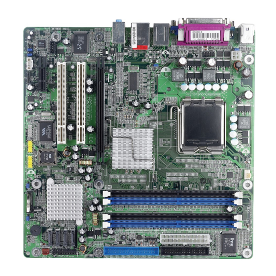
SATA 4 panel RTL8110SB SATA 3 Intel PCI 2 ICH6 SATA 2 SATA 1 CD-in PCIE x1 BIOS VT6307 Audio USB 5-8 power Chassis fan CODEC Clear CMOS select (JP1) (JP4) Battery Front audio 1394_2 USB 5-6 USB 7-8 S/PDIF G7G330-B... - Page 17 Hardware Installation CPU fan PS/2 power select (JP3) DDR 2 DDR 4 Mouse DDR 1 DDR 3 +12V power IT8712F COM 1 ATX power Parallel COM 2 1394_1 USB 1-2 USB 1-4 power IrDA select (JP2) USB 3-4 Intel 915GV Line-in Line-out Mic-in...
-
Page 18: System Memory
Hardware Installation Warning: Electrostatic discharge (ESD) can damage your system board, processor, disk drives, add-in boards, and other components. Perform the upgrade instruction procedures described at an ESD workstation only. If such a station is not available, you can provide some ESD protection by wearing an antistatic wrist strap and attaching it to a metal part of the system chassis. - Page 19 Hardware Installation The system board supports the following memory interface. Single Channel (SC) Data will be accessed in chunks of 64 bits (8B) from the memory channels. Virtual Single Channel (VSC) If both channels are populated with different memory configurations, the MCH defaults to Virtual Single Channel.
- Page 20 Hardware Installation The table below lists the various optimal operating modes that should be configured for the memory channel operation. DDR 3 DDR 4 Config DDR 1 DDR 2 No memory Single channel A Single channel A Single channel A Single channel B Single channel B Single channel B...
- Page 21 Hardware Installation DDR 3 DDR 4 DDR 1 DDR 2 Config P(*)(2,4) Dynamic Mode Addressing P(*)(2,4) P(*)(1,3) P(*)(1,3) Dynamic Mode Addressing P(*)(1,3) P(*)(2,4) Dynamic Mode Addressing P(*)(1,3) P(*)(2,4) P(*)(2,4) P(*)(2,4) Dynamic Mode Addressing P(*)(1,3) P(*)(1,3) Dynamic Mode Addressing P(*)(1,3) P(*)(2,4) P(*)(1,3) P(*)(2,4) Dynamic Mode Addressing...
- Page 22 Hardware Installation 2.2.1 Installing the DIMM A DIMM simply snaps into a DIMM socket on the system board. Pin 1 of the DIMM must correspond with Pin 1 of the socket. Notch Pin 1 1. Pull the “tabs” which are at the ends of the socket to the side. 2.
-
Page 23: Cpu
Hardware Installation 2.3 CPU 2.3.1 Overview The system board is equipped with a surface mount LGA 775 socket. This socket is exclusively designed for installing a LGA 775 packaged Prescott CPU. Important: 1. Before you proceed, make sure (1) the LGA775 1. - Page 24 Hardware Installation Important: The CPU socket must not come in contact with anything other than the CPU. Avoid unnecessary exposure. Remove the protective cap only when you are about to install the CPU. 4. The CPU socket comes with a cover that is attached with a removable protective cap.
- Page 25 Hardware Installation 7. Now lift the cover. Cover 8. Position the CPU above the socket. The gold mark on the CPU must align with pin 1 of the CPU socket. Important: Handle the CPU by its edges and avoid touching the pins. Gold mark Pin 1 of the socket...
- Page 26 Hardware Installation 9. Insert the CPU into the socket until it is seated in place. The CPU will fit in only one orientation and can easily be inserted without exerting any force. Important: Do not force the CPU into the socket. Forcing the CPU into the socket may bend the pins and damage the CPU.
- Page 27 Hardware Installation 11. Push the lever down to lock the socket. The lever should hook onto the side tab to indicate that the CPU is completely secured in the socket. 2.3.3 Installing the Fan and Heat Sink The CPU must be kept cool by using a CPU fan with heat sink. Without sufficient air circulation across the CPU and heat sink, the CPU will overheat damaging both the CPU and system board.
- Page 28 Hardware Installation 2. Place the heat sink on top of the CPU. The 4 studs around the heat sink which are used to secure the heat sink onto the system board must match the 4 mounting holes around the socket. Position each stud so that the groove faces the heat sink then push it down firmly until it clicks into place.
-
Page 29: Jumper Settings
Hardware Installation 2.4 Jumper Settings 2.4.1 Clear CMOS Data 1-2 On: Normal (default) 2-3 On: Clear CMOS Data If you encounter the following, a) CMOS data becomes corrupted. b) You forgot the supervisor or user password. c) You are unable to boot-up the computer system because the processor’s ratio/clock was incorrectly set in the BIOS. - Page 30 Hardware Installation 4. After powering-on the system, press <Del> to enter the main menu of the BIOS. 5. Select the Frequency/Voltage Control submenu and press <Enter>. 6. Set the processor’s clock/ratio to its default setting or an appropriate bus clock or ratio. Refer to the Frequency/Voltage Control section in chapter 3 for more information.
- Page 31 Hardware Installation 2.4.2 PS/2 Power Select 2-3 On: 5VSB 1-2 On: 5V (default) JP3 is used to select the power of the PS/2 keyboard/mouse port. Selecting 5VSB will allow you to use the PS/2 keyboard or PS/2 mouse to wake up the system. BIOS Setting Configure the PS/2 keyboard/mouse wake up function in the Integrated Peripherals submenu (“Super IO Device”...
- Page 32 Hardware Installation 2.4.3 USB Power Select USB 1-4 (JP2) 2-3 On: 5VSB 1-2 On: 5V (default) USB 5-8 1-2 On: 5V 2-3 On: 5VSB (JP1) (default) JP1 and JP2 are used to select the power of the USB ports. Selecting 5VSB will allow you to use the USB keyboard or USB mouse to wake up the system.
-
Page 33: Rear Panel I/O Ports
The rear panel I/O ports consist of the following: • PS/2 mouse port • PS/2 keyboard port • Parallel port • COM port • VGA port • IEEE 1394_1 port (optional on G7G330-B) • USB ports • LAN port • Line-in jack • Line-out jack • Mic-in jack... - Page 34 Hardware Installation 2.5.1 PS/2 Mouse and PS/2 Keyboard Ports PS/2 Mouse PS/2 Keyboard The system board is equipped with an onboard PS/2 mouse (Green) and PS/2 keyboard (Purple) ports - both at location CN7 of the system board. The PS/2 mouse port uses IRQ12. If a mouse is not connected to this port, the system will reserve IRQ12 for other expansion cards.
- Page 35 Hardware Installation 2.5.2 Serial Port COM 1 The system board is equipped with an onboard serial port (Teal/ Turquoise) at location CN5 for COM 1. It is also equipped with a 9-pin connector at location J9 for COM 2. The serial ports are RS-232C asynchronous communication por t with 16C550A- compatible UARTs that can be used with a modem, serial printer, remote display terminal or other serial devices.
- Page 36 Hardware Installation 2.5.3 Parallel Port Parallel The system board has a standard parallel port (Burgundy) at loca- tion CN4 for interfacing your PC to a parallel printer. It supports SPP, ECP and EPP. Setting Function Allows normal speed operation but (Standard Parallel Port) in one direction only.
- Page 37 Hardware Installation 2.5.4 VGA Port The system board can only be used with an analog video monitor. Connect the monitor’s 15-pin D-shell cable connector to the VGA port (Blue) at location CN6. If your monitor supports analog video but does not have a 15-pin D-shell connector, see your monitor dealer for the adapter or optional cable.
- Page 38 Hardware Installation 2.5.5 IEEE 1394 (optional on G7G330-B) 1394_1 1394_2 The system board is equipped with an onboard IEEE 1394 port at location CN1 (IEEE 1394_1). It is also equipped with an IEEE 1394 connector at location J1 (1394_2) for connecting an additional 1394 port. The 1394 port may be mounted on a card-edge bracket.
- Page 39 Hardware Installation 2.5.6 USB Ports USB 2 USB 1 USB 4 USB 3 USB 5-6 USB 7-8 The system board supports 8 USB 2.0/1.1 ports. USB allows data exchange between your computer and a wide range of simultaneously accessible external Plug and Play peripherals. Four onboard USB 2.0/1.1 ports (Black) are at locations CN1 (USB 1-2) and CN2 (USB 3-4) of the system board.
- Page 40 Hardware Installation Driver Installation You may need to install the proper drivers in your operating system to use the USB device. Refer to your operating system’s manual or documentation for more information. Refer to chapter 4 for more information about installing the USB 2.0 driver.
- Page 41 Hardware Installation 2.5.7 RJ45 LAN Port The RJ45 LAN port is at location CN2 of the system board. LAN allows the system board to connect to a local area network by means of a network hub. BIOS Setting Configure the onboard LAN in the in the Integrated Peripherals submenu (“Onboard Device”...
- Page 42 Hardware Installation 2.5.8 Audio (Rear Audio and Front Audio) Line-in Line-out Rear Audio Mic-in Front audio Rear Panel Audio • Line-in (Light Blue) In a 2-channel or 4-channel mode, this jack is used to connect any audio devices such as Hi-fi set, CD player, tape player, AM/ FM radio tuner, synthesizer, etc.
- Page 43 Hardware Installation 4-channel 2-channel 6-channel Line-in Light Blue Line-in Center/Subwoofer Front R/L Lime Line-out Front R/L Rear R/L Pink Mic-in Rear R/L Front Audio The front audio connector (J4) allows you to connect to the line-out and mic-in jacks that are at the front panel of your system. Using this connector will disable the rear audio’s line-out and mic-in func- tions.
-
Page 44: I/O Connectors
Hardware Installation 2.6 I/O Connectors 2.6.1 CD-in Internal Audio Connector Ground Ground Right audio Left audio channel channel The CD-in (J6) connector is used to receive audio from a CD-ROM drive, TV tuner or MPEG card. - Page 45 Hardware Installation 2.6.2 S/PDIF SPDIF out SPDIF in The system board is equipped with a S/PDIF connector. One card- edge bracket, mounted with S/PDIF ports, may be provided with the system board. Install the card-edge bracket to the system chassis then connect the audio cable connector to J5.
- Page 46 Hardware Installation 2.6.3 Floppy Disk Drive Connector The system board is equipped with a shrouded floppy disk drive connector that supports two standard floppy disk drives. To prevent improper floppy cable installation, the shrouded floppy disk header has a keying mechanism. The 34-pin connector on the floppy cable can be placed into the header only if pin 1 of the connector is aligned with pin 1 of the header.
- Page 47 Hardware Installation 2.6.4 Serial ATA Connectors SATA 4 SATA 3 SATA 2 SATA 1 The system board is equipped with four Serial ATA connectors for connecting Serial ATA devices. Connect one end of the Serial ATA cable to J15 (SATA 1), J16 (SATA 2), J17 (SATA 3) or J18 (SATA 4) and the other end to your Serial ATA device.
- Page 48 Hardware Installation 2.6.5 IDE Disk Drive Connector The system board is equipped with a shrouded PCI IDE header that will interface two Enhanced IDE (Integrated Drive Electronics) disk drives. To prevent improper IDE cable installation, the shrouded PCI IDE header has a keying mechanism. The 40-pin connector on the IDE cable can be placed into the header only if pin 1 of the connector is aligned with pin 1 of the header.
- Page 49 Hardware Installation Adding a Second IDE Disk Drive When using two IDE drives, one must be set as the master and the other as the slave. Follow the instructions provided by the drive manufacturer for setting the jumpers and/or switches on the drives. The system board suppor ts Enhanced IDE or ATA-2, ATA/33, ATA/66 or ATA/100 hard drives.
- Page 50 Hardware Installation 2.6.6 IrDA Connector N. C. IRRX Ground IRTX Connect the cable connector from your IR module to the IR connector (J13). Note: The sequence of the pin functions on some IR cable may be reversed from the pin function defined on the system board. Make sure to connect the cable connector to the IR connector according to their pin functions.
- Page 51 Hardware Installation 2.6.7 Cooling Fan Connectors Speed Ground Control Power Sense CPU fan Sense Power Ground Chassis fan Connect the CPU fan’s cable connector to the CPU fan connector (J8) on the system board. The chassis fan connector (J10) is used to connect an additional cooling fan.
- Page 52 Hardware Installation 2.6.8 Power Connectors +12V +12V Ground Ground 1 2 2 4 Ground +3.3VDC +12VDC +5VDC +12VDC +5VDC +5VDC +5VSB PWR_OK Ground Ground Ground +5VDC Ground Ground PS_ON# +5VDC Ground Ground -12VDC +3.3VDC +3.3VDC +3.3VDC We recommend that you use a power supply that complies with the ATX12V Power Supply Design Guide Version 1.1.
- Page 53 Hardware Installation 2.6.9 Front Panel Connectors 2 01 9 SPEAKER RESET ATX-SW HD-LED PWR-LED HD-LED: Primary/Secondary IDE LED This LED will light when the hard drive is being accessed. RESET: Reset Switch This switch allows you to reboot without having to power off the system thus prolonging the life of the power supply or system.
- Page 54 Hardware Installation PWR-LED: Power/Standby LED When the system’s power is on, this LED will light. When the system is in the S1 (POS - Power On Suspend) or S3 (STR - Suspend To RAM) state, it will blink every second. Note: If a system did not boot-up and the Power/Standby LED did not light after it was powered-on, it may indicate that the CPU...
- Page 55 Hardware Installation 2.6.10 PCI Express x16 and x1 Slots PCI Express x16 PCI Express x1 The system board is equipped with one PCI Express x16 and one PCI Express x1 slots. Note: On G7V330-B, this slot supports ADD2 card only. PCI Express x16 Install PCI Express x16 graphics card, that comply to the PCI Express specifications, into the PCI Express x16 slot.
-
Page 56: Chapter 3 - Bios Setup
BIOS Setup Chapter 3 - BIOS Setup 3.1 Award BIOS Setup Utility The Basic Input/Output System (BIOS) is a program that takes care of the basic level of communication between the processor and peripherals. In addition, the BIOS also contains codes for various advanced features found in this system board. - Page 57 BIOS Setup 3.1.1 Standard CMOS Features Use the arrow keys to highlight “Standard CMOS Features” and press <Enter>. A screen similar to the one below will appear. The settings on the screen are for reference only. Your version may not be identical to this one.
- Page 58 BIOS Setup 3.1.1.3 IDE Channel 0 Master/Slave and IDE Channel 1 Master/Slave Move the cursor to the “IDE Channel 0 Master”, “IDE Channel 0 Slave”, “IDE Channel 1 Master” or “IDE Channel 1 Slave” field, then press <Enter>. The settings on the screen are for reference only. Your version may not be identical to this one.
- Page 59 BIOS Setup Access Mode For hard drives larger than 528MB, you would typically select the LBA type. Certain operating systems require that you select CHS or Large. Please check your operating system’s manual or Help desk on which one to select. Capacity Displays the approximate capacity of the disk drive.
- Page 60 BIOS Setup 3.1.1.5 Video This field selects the type of video adapter used for the primary system monitor. Although secondary monitors are supported, you do not have to select the type. The default setting is EGA/VGA. EGA/VGA Enhanced Graphics Adapter/Video Graphics Array. For EGA, VGA, SVGA and PGA monitor adapters.
- Page 61 BIOS Setup 3.1.1.8 Extended Memory Displays the amount of extended memory detected during boot-up. 3.1.1.9 Total Memory Displays the total memory available in the system.
- Page 62 BIOS Setup 3.1.2 Advanced BIOS Features The Advanced BIOS Features allows you to configure your system for basic operation. Some entries are defaults required by the system board, while others, if enabled, will improve the performance of your system or let you set some features according to your preference. The screen above list all the fields available in the Advanced BIOS Features submenu, for ease of reference in this manual.
- Page 63 BIOS Setup 3.1.2.1 CPU Feature Move the cursor to this field and press <Enter>. The following screen will appear. The settings on the screen are for reference only. Your version may not be identical to this one. Delay Prior To Thermal This field is used to select the time that would force the CPU to a 50% duty cycle when it exceeds its maximum operating temperature therefore protecting the CPU and the system board from...
- Page 64 BIOS Setup Limit CPUID MaxVal The CPUID instruction of some newer CPUs will return a value greater than 3. The default is Disabled because this problem does not exist in the Windows series operating systems. If you are using an operating system other than Windows, this problem may occur. To avoid this problem, enable this field to limit the return value to 3 or lesser than 3.
- Page 65 BIOS Setup 3.1.2.3 Virus Warning This field protects the boot sector and partition table of your hard disk drive. When this field is enabled, the Award BIOS will monitor the boot sector and partition table of the hard disk drive. If an attempt is made to write to the boot sector or partition table of the hard disk drive, the BIOS will halt the system and an error message will appear.
- Page 66 BIOS Setup 3.1.2.8 First Boot Device, Second Boot Device, Third Boot Device and Boot Other Device Select the drive to boot first, second and third in the “First Boot Device” “Second Boot Device” and “Third Boot Device” fields respectively. The BIOS will boot the operating system according to the sequence of the drive selected.
- Page 67 BIOS Setup 3.1.2.13 Typematic Rate Setting Disabled Continually holding down a key on your keyboard will cause the BIOS to report that the key is down. Enabled The BIOS will not only report that the key is down, but will first wait for a moment, and, if the key is still down, it will begin to report that the key has been depressed repeatedly.
- Page 68 BIOS Setup 3.1.2.18 MPS Version Control for OS This field is used to select the MPS version that the system board is using. 3.1.2.19 OS Select for DRAM > 64MB This field allows you to access the memory that is over 64MB in OS/2.
- Page 69 BIOS Setup 3.1.3 Advanced Chipset Features The settings on the screen are for reference only. Your version may not be identical to this one. This section gives you functions to configure the system based on the specific features of the chipset. The chipset manages bus speeds and access to system memory resources.
- Page 70 BIOS Setup select the best option in the “CAS Latency Time” to “System Memory Frequency” fields. 3.1.3.2 CAS Latency Time This field is used to select the latency between the DRAM read command and the time that the data was received. 3.1.3.3 DRAM RAS# to CAS# Delay This field is used to select the latency between the DRAM active command and the read/write command.
- Page 71 15-16MB address range actually contains DRAM memory. If more than 16MB of system memory is installed, this field must be disabled to provide contiguous system memory. 3.1.3.11 PCI Express Root Port Func (G7G330-B only) Move the cursor to this field and press <Enter>. The following screen will appear.
- Page 72 BIOS Setup 3.1.3.12 PEG/Onchip VGA Control This field is used to select the graphics controller that will serve as the primary boot device. The options are Auto, Onchip VGA and PEG Port. 3.1.3.13 PEG Force X1 The options are Enabled and Disabled. 3.1.3.14 On-Chip Video Memory Size This field is used to select the graphics memory size.
- Page 73 BIOS Setup 3.1.3.19 Boot Display This field is used to select the type of display to use when the system boots. Auto The system will automatically detect the display that is available when the system boots. Select this option if you want the system to boot the CRT display.
- Page 74 BIOS Setup 3.1.4 Integrated Peripherals The settings on the screen are for reference only. Your version may not be identical to this one. 3.1.4.1 OnChip IDE Device Move the cursor to this field and press <Enter>. The following screen will appear. The settings on the screen are for reference only.
- Page 75 BIOS Setup IDE HDD Block Mode Enabled The IDE HDD uses the block mode. The system BIOS will check the hard disk drive for the maxi- mum block size the system can transfer. The block size will depend on the type of hard disk drive. Disabled The IDE HDD uses the standard mode.
- Page 76 BIOS Setup On-Chip Serial ATA Setting On-Chip Serial ATA Disabled Disables the onboard SATA. Auto The system will detect the existing SATA and IDE drives then automatically set them to the available master/slave mode. Combined Mode This option allows you to use both IDE and SATA drives;...
- Page 77 BIOS Setup SATA Port If the “PATA IDE Mode” field is set to Primary, this field will show “P1, P3 is Secondary”; meaning SATA 2 and SATA 4 are Secondary. If the “PATA IDE Mode” field is set to Secondary, this field will show “P0, P2 is Primary”;...
- Page 78 BIOS Setup AC97 Audio Auto Select this option when using the onboard audio CODEC. Disabled Select this option when using a PCI sound card. Onboard LAN Control This field is used to enable or disable the onboard LAN.
- Page 79 BIOS Setup 3.1.4.3 Super IO Device Move the cursor to this field and press <Enter>. The following screen will appear. The settings on the screen are for reference only. Your version may not be identical to this one. Power On Function This field allows you to use the keyboard or PS/2 mouse to power- on the system.
- Page 80 BIOS Setup KB Power On Password Move the cursor to this field and press <Enter>. Enter your pass- word. You can enter up to 5 characters. Type in exactly the same password to confirm, then press <Enter>. The power button will not function once a keyboard password has been set in this field.
- Page 81 BIOS Setup Onboard Parallel Port 378/IRQ7, 3BC/IRQ7, 278/IRQ5 Selects the I/O address and IRQ for the onboard parallel port. Disabled Disables the onboard parallel port. Parallel Port Mode The options are SPP, EPP, ECP and ECP+EPP. These apply to a standard specification and will depend on the type and speed of your device.
- Page 82 BIOS Setup 3.1.5 Power Management Setup The Power Management Setup allows you to configure your system to most effectively save energy. The screen above list all the fields available in the Power Management Setup submenu, for ease of reference in this manual. In the actual CMOS setup, you have to use the scroll bar to view the fields.
- Page 83 BIOS Setup 3.1.5.4 Power Management This field allows you to select the type (or degree) of power saving by changing the length of idle time that elapses before the Suspend mode and HDD Power Down fields are activated. Min Saving Minimum power saving time for the Suspend Mode (1 hour) and HDD Power Down (15 min.) Max Saving...
- Page 84 BIOS Setup 3.1.5.9 Suspend Mode This is selectable only when the Power Management field is set to User Define. When the system enters the Suspend mode according to the power saving time selected, the CPU and onboard peripherals will be shut off. 3.1.5.10 HDD Power Down This is selectable only when the Power Management field is set to User Define.
- Page 85 BIOS Setup 3.1.5.13 Wake-Up By PCI Card Enabled This field should be set to Enabled only if your PCI card such as LAN card or modem card uses the PCI PME (Power Management Event) signal to remotely wake up the system. Access to the LAN card or PCI card will cause the system to wake up.
- Page 86 BIOS Setup 3.1.5.18 Time (hh:mm:ss) Alarm This is used to set the time you would like the system to power-on. If you want the system to power-on everyday as set in the “Date (of Month) Alarm” field, the time set in this field must be later than the time of the RTC set in the Standard CMOS Features submenu.
- Page 87 BIOS Setup 3.1.6 PnP/PCI Configurations This section describes configuring the PCI bus system. It covers some very technical items and it is strongly recommended that only experienced users should make any changes to the default settings. The settings on the screen are for reference only. Your version may not be identical to this one.
- Page 88 BIOS Setup 3.1.6.3 Resources Controlled By The Award Plug and Play BIOS has the capability to automatically configure all of the boot and Plug and Play compatible devices. Auto The system will automatically detect the settings for you. Manual Choose the specific IRQ in the “IRQ Resources” field respectively.
- Page 89 BIOS Setup 3.1.6.7 Maximum Payload Size This field is used to select the maximum TLP payload size of the PCI Express devices. The unit is byte.
- Page 90 BIOS Setup 3.1.7 PC Health Status The settings on the screen are for reference only. Your version may not be identical to this one. 3.1.7.1 Shutdown Temperature You can prevent the system from overheating by selecting a tem- perature in this field. If the system detected that its temperature exceeded the one set in this field, it will automatically shutdown.
- Page 91 BIOS Setup 3.1.8 Frequency/Voltage Control The settings on the screen are for reference only. Your version may not be identical to this one. 3.1.8.1 CPU Clock Ratio This field is used to select the CPU’s frequency ratio. Important: The frequency ratio of some processors may have been locked by the manufacturer.
- Page 92 BIOS Setup 3.1.8.4 CPU Clock This field provides several options for selecting the external system bus clock of the processor. The available options allow you to adjust the processor’s bus clock by 1MHz increment. Important: Selecting an external bus clock other than the default setting may result to the processor’s or system’s instability and are not guaranteed to provide better system performance.
- Page 93 BIOS Setup 3.1.9 Load Fail-Safe Defaults The “Load Fail-Safe Defaults” option loads the troubleshooting default values permanently stored in the ROM chips. These settings are not optimal and turn off all high performance features. You should use these values only if you have hardware problems. Highlight this option in the main menu and press <Enter>.
- Page 94 BIOS Setup 3.1.10 Load Optimized Defaults The “Load Optimized Defaults” option loads optimized settings from the BIOS ROM. Use the default values as standard values for your system. Highlight this option in the main menu and press <Enter>. Type <Y> and press <Enter> to load the Setup default values.
- Page 95 BIOS Setup 3.1.11 Set Supervisor Password If you want to protect your system and setup from unauthorized entry, set a supervisor’s password with the “System” option selected in the Advanced BIOS Features. If you want to protect access to setup only, but not your system, set a supervisor’s password with the “Setup”...
- Page 96 BIOS Setup 3.1.12 Set User Password If you want another user to have access only to your system but not to setup, set a user’s password with the “System” option se- lected in the Advanced BIOS Features. If you want a user to enter a password when trying to access setup, set a user’s password with the “Setup”...
- Page 97 BIOS Setup 3.1.13 Save & Exit Setup When all the changes have been made, highlight “Save & Exit Setup” and press <Enter>. Type “Y” and press <Enter>. The modifications you have made will be written into the CMOS memory, and the system will reboot. You will once again see the initial diagnostics on the screen.
- Page 98 BIOS Setup 3.1.14 Exit Without Saving When you do not want to save the changes you have made, highlight “Exit Without Saving” and press <Enter>. Type “Y” and press <Enter>. The system will reboot and you will once again see the initial diagnostics on the screen. If you wish to make any changes to the setup, press <Ctrl>...
-
Page 99: Updating The Bios
BIOS Setup 3.2 Updating the BIOS To update the BIOS, you will need the new BIOS file and a flash utility, AWDFLASH.EXE. Please contact technical support or your sales representative for the files. 1. Save the new BIOS file along with the flash utility AWDFLASH.EXE to a floppy disk. - Page 100 BIOS Setup 6. The following will appear. Do You Want to Save BIOS (Y/N) This question refers to the current existing BIOS in your system. We recommend that you save the current BIOS and its flash utility; just in case you need to reinstall the BIOS. To save the current BIOS, press <Y>...
-
Page 101: Chapter 4 - Supported Softwares
Supported Software Chapter 4 - Supported Software 4.1 Drivers, Utilities and Software Applications The CD that came with the system board contains drivers, utilities and software applications required to enhance the performance of the system board. Inser t the CD into a CD-ROM drive. The autorun screen (Mainboard Utility CD) will appear. - Page 102 Supported Software 4.1.1 Intel Chipset Software Installation Utility The Intel Chipset Software Installation Utility is used for updating Windows 2000/ME/XP's INF files so that the Intel chipset can be recognized and configured properly in the system. To install the utility, please follow the steps below. 1.
- Page 103 Supported Software 4.1.2 Intel Graphics Media Accelerator Driver To install the driver, please follow the steps below. 1. On the left side of the autorun screen, click the “GRAPHICS” icon. 2. Click “Intel Graphics Media Accelerator Driver” on the main menu.
- Page 104 Supported Software 4.1.3 Realtek Audio Driver To install the driver, please follow the steps below. 1. On the left side of the autorun screen, click the “AUDIO” icon. 2. Click “Realtek Audio Driver” on the main menu. The following screen will appear. 3.
- Page 105 Supported Software 4.1.4 Realtek LAN Driver To install the driver, please follow the steps below. 1. On the left side of the autorun screen, click the “NETWORK” icon. 2. Click “Realtek LAN Driver” on the main menu. The following screen will appear. 3.
- Page 106 Supported Software 4.1.5 Hardware Monitor The system board comes with the Hardware Monitor utility con- tained in the provided CD. This utility is capable of monitoring the system’s temperature, fan speed, voltage, etc. and allows you to manually set a range (Highest and Lowest Limit) to the items being monitored.
- Page 107 Supported Software 4.1.6 Microsoft DirectX 9 To install, please follow the steps below. 1. On the left side of the autorun screen, click the “TOOLS” icon. 2. Click “Microsoft DirectX 9” on the main menu. The following screen will appear. 3.
-
Page 108: Installation Notes
Supported Software 4.1.7 Intel USB 2.0 Drivers The Intel chipset does not support USB 2.0 drivers for Windows 98 SE and Windows ® Windows ® If your Windows XP CD already includes Service Pack 1, the USB 2.0 driver will automatically install when you install the operating system. -
Page 109: Enabling The Hyper-Threading Technology
Enabling Hyper-Threading Technology Appendix A - Enabling Hyper-Threading Technology A.1 Enabling Hyper-Threading Technology To enable the functionality of the Hyper-Threading Technology, please follow the requirements and steps below. Basically, the following ® ® presumes that you have already installed an Intel Pentium Processor with Hyper-Threading Technology. - Page 110 Enabling Hyper-Threading Technology Click the General tab. The processor shown under Computer should resemble the one shown below. Now click the Hardware tab then click Device Manager. The items shown under Computer and Processors should resemble the ones shown below.
- Page 111 Enabling Hyper-Threading Technology Lastly, press the <Ctr l> <Alt> and <Del> keys simultaneously. The Windows Task Manager dialog box will appear. Click the Performance tab. The diagram under CPU Usage History should resemble the one shown below.
-
Page 112: Appendix B - System Error Messages
System Error Message Appendix B - System Error Message When the BIOS encounters an error that requires the user to cor- rect something, either a beep code will sound or a message will be displayed in a box in the middle of the screen and the message, PRESS F1 TO CONTINUE, CTRL-ALT-ESC or DEL TO ENTER SETUP, will be shown in the information box at the bottom. - Page 113 System Error Message Hard Disk(s) fail (80) HDD reset failed. Hard Disk(s) fail (40) HDD controller diagnostics failed. Hard Disk(s) fail (20) HDD initialization error. Hard Disk(s) fail (10) Unable to recalibrate fixed disk. Hard Disk(s) fail (08) Sector Verify failed. Keyboard is locked out - Unlock the key The BIOS detects that the keyboard is locked.
-
Page 114: Appendix C - Troubleshooting
Troubleshooting Appendix C - Troubleshooting C.1 Troubleshooting Checklist This chapter of the manual is designed to help you with problems that you may encounter with your personal computer. To efficiently troubleshoot your system, treat each problem individually. This is to ensure an accurate diagnosis of the problem in case a problem has multiple causes. - Page 115 Troubleshooting The picture seems to be constantly moving. 1. The monitor has lost its vertical sync. Adjust the monitor’s verti- cal sync. 2. Move away any objects, such as another monitor or fan, that may be creating a magnetic field around the display. 3.
- Page 116 Troubleshooting Hard Drive Hard disk failure. 1. Make sure the correct drive type for the hard disk drive has been entered in the BIOS. 2. If the system is configured with two hard drives, make sure the bootable (first) hard drive is configured as Master and the sec- ond hard drive is configured as Slave.
- Page 117 Troubleshooting 3. Verify that the attached serial device works by attaching it to a serial port that is working and configured correctly. If the serial device does not work, either the cable or the serial device has a problem. If the serial device works, the problem may be due to the onboard I/O or the address setting.
Need help?
Do you have a question about the G7G330-B and is the answer not in the manual?
Questions and answers