
Related Manuals for DFI GH551


Summary of Contents for DFI GH551
- Page 1 GH551 Embedded SBC 3.5” Industrial Motherboard User’s Manual Preliminary Preliminary Version Version A-595-M-2019...
- Page 2 1. The changes or modifications not expressly approved by the party responsible for com- pliance could void the user’s authority to operate the equipment. 2. Shielded interface cables must be used in order to comply with the emission limits. User's Manual | GH551...
-
Page 3: Table Of Contents
Overview ..........................25 Main ............................26 Advanced ..........................26 PTN3460 Config ......................27 NCT5525D Super IO Configuration ................27 NCT5525D HW Monitor ....................28 AMD CHIPSET Setting ....................29 Trusted Computing ......................31 ACPI Configuration ......................32 CPU Configuration ......................32 Serial Port Console Redirection ...................33 User's Manual | GH551... - Page 4 • To reduce the risk of electric shock, unplug the power cord before removing the sys- tem chassis cover for installation or servicing. After installation or servicing, cover the system chassis before plugging the power cord. User's Manual | GH551...
- Page 5 • Storage device such as hard disk drive, CD-ROM, etc. • Power adaptor External system peripherals may also be required for navigation and display, including at least a keyboard, a mouse and a video display monitor. User's Manual | GH551...
-
Page 6: Chapter 1 - Introduction
Please visit the download page at go.dfi. Audio 1 x Mic-in com/GH551, or via the QR code to the right for the latest datasheet. 1 x Line-out 1 x Speaker-out (2 x 3W, 8ohm) SATA 1 x SATA 3.0 (up to 6Gb/s) -
Page 7: Features
Event) signal. However, if your system is in the Suspend mode, you can power-on the system only through an IRQ or DMA interrupt. Wake-On-USB This function allows you to use a USB keyboard or USB mouse to wake up a system from the S3 (STR - Suspend To RAM) state. User's Manual | GH551... -
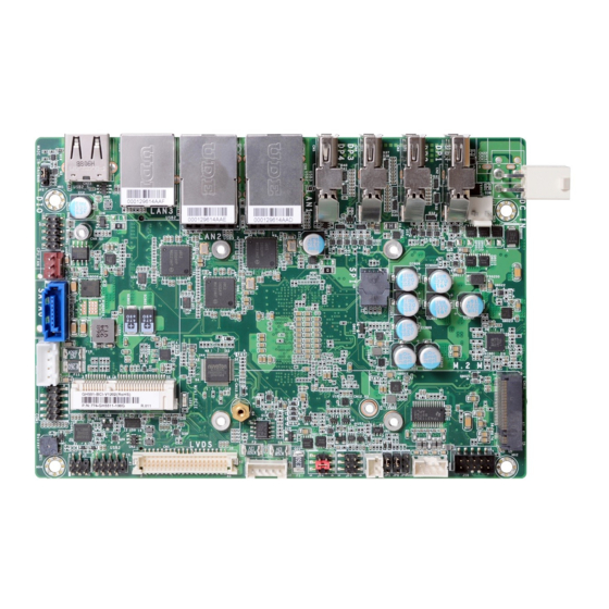
Page 8: Chapter 2 - Hardware Installation
Power-off the PC then unplug the power cord prior to installing any devices. Failure to do so will cause severe damage to the motherboard and com- Nano SIM (Bottom) LAN3 ponents. LAN2, USB 3.0 User's Manual | GH551... -
Page 9: System Memory
Data will be accessed in chunks of 64 bits from the memory channels. Socket Top View Features • 1 x 260-pin SODIMM up to 16GB • Single Channel DDR4 up to 2400MHz 4 5 ° Step 1 User's Manual | GH551... -
Page 10: Heatsink And Fan
CPU Fan click, and lock the card in place. Inspect that the clip sits in the notch. If not, please pull the clips outward, release and remove the Step 3 card, and mount it again. User's Manual | GH551... -
Page 11: Jumper Settings
Power On Suspend) state, it will blink at 1-second intervals. When the system is in the S3 (STR - Suspend To RAM) state, it will blink at 4-second intervals. „ 1-2 On: Normal (default) „ 2-3 On: Clear CMOS Power Button This switch is used to power on or off the system. User's Manual | GH551... -
Page 12: Panel Power Select (Jp4)
Before powering-on the system, make sure that the setting of the jumper matches the specifications of the LVDS LCD. Incorrect power voltage may cause irreversible the specifications of the LCD's backlight power. Incorrect power voltage may damage to your LCD panel. cause irreversible damage to your LCD's backlight. User's Manual | GH551... -
Page 13: Apu Power (Jp9000)
The APU VRM can be monitored via the connector. The system board can be switched between AT and ATX modes via JP6. Assignment APU_VRM1_SCLK APU_VRM1_SDATA „ 1-2 On: AT Mode (default) „ 2-3 On: ATX Mode User's Manual | GH551... -
Page 14: Rear I/O Ports
BIOS. Configure the LVDS LCD panel in the Advanced > PTN3460 Config sub- menu. Refer to the chapter 3 for more information. Driver Installation Install the graphics driver. Refer to the chapter 4 for more information. User's Manual | GH551... -
Page 15: Usb Ports
Install the LAN drivers. Refer to the chapter 4 for more information. BIOS Setting Configure the onboard USB in the Advanced menu (“USB Configuration” submenu) of the BIOS. Refer to chapter 3 for more information. Features • 3 x Realtek RTL8111HN/RTL8119I (10/100/1000Mbps) ® User's Manual | GH551... -
Page 16: Internal I/O Connectors
Using a voltage higher than the recommended range may result in failure in start- ing and booting the system or causing irreversible damage to the system board. A power adaptor/converter is necessary when the power source on site does not comply with the power specifications of the board. User's Manual | GH551... -
Page 17: Front Audio
Pin Assignment Pin Assignment The Wake-On-USB Keyboard/Mouse function allows you to use a USB keyboard or USB mouse to wake up a system from the S state(s). Mic-L Mic-R N.C. Line-Out-R Mic-JD (sense) N.C. Line-Out-L Line-JD (sense) User's Manual | GH551... -
Page 18: Speaker
Configure the Serial ATA drives in the Advanced > AMD CHIPSET Setting > SATA Configuration Options submenu of the BIOS. Refer to chapter 3 for more information. „ Speaker Pin Assignment Assignment „ SATA Power Pin Assignment „ SATA Pin Assignment SPK_Out_L+ SPK_Out_L- SPK_Out_R- SPK_Out_R+ N.C. User's Manual | GH551... -
Page 19: Battery
• There exists explosion hazard if the battery is incorrectly installed. Ground • Replace only with the same or equivalent type recommended by the manufacturer. Power • Dispose of used batteries according to local ordinances. Sense User's Manual | GH551... -
Page 20: Digital I/O
„ Digital I/O Pin Assignment „ SMBus Pin Assignment Pin Assignment Pin Assignment Pin Assignment Pin Assignment DIO_7 DIO_6 3V3SB DIO_3 DIO_4 SMBus_Clock SMBus_DATA DIO_5 DIO_2 SMBus_Alert DIO_1 DIO_0 5VSB User's Manual | GH551... -
Page 21: Lvds Panel (Optional)
„ Backlight Power Pin Function Pin Function Pin Assignment +12V PWM Brightness Control Note: The LVDS port is only available on certain models. Please refer to specifications for detail. Backlight On/Off User's Manual | GH551... -
Page 22: Heater
— one USB 2.0, and one USB 3.0. Pin Assignment Pin Assignment Nano SIM The Nano SIM socket allows for inserting a Nano SIM card for the system to access the sub- 12VSB_PG_SW scribed telecom service. User's Manual | GH551... -
Page 23: Installing The M.2 Module
The M.2 stand-off is detachable and is screwed onto one of the reserved bases for the supported form factors. Please remove and install it into the base of the form factor that matches the M.2 module to be installed. User's Manual | GH551... -
Page 24: Installing The Mini Pcie Module
Screw tight the card onto the stand- off with a screw driver and a stand- off screw until the gap between the card and the stand-off closes up. The card should be lying paral- lel to the board when it’s correctly mounted. User's Manual | GH551... -
Page 25: Chapter 3 - Bios Settings
When “X” appears on the left of a particular field, it indicates that a submenu which contains additional options are available for that field. To display the submenu, move the highlight to that field and press <Enter>. User's Manual | GH551... -
Page 26: Main
The time format is <hour>, <minute>, <second>. The time is based on the 24-hour military-time clock. For example, 1 p.m. is 13:00:00. Hour displays hours from 00 to 23. Minute displays min- utes from 00 to 59. Second displays seconds from 00 to 59. User's Manual | GH551... -
Page 27: Ptn3460 Config
Select the color depth of the LCD Panel — 18 Bit, 24 Bit, 36 Bit, 48 Bit. Backlight Type Select the inverter polarity and brightness control — PWM Mdde, DC Mdde. Note: The sub-menus are detailed in following sections. User's Manual | GH551... -
Page 28: Nct5525D Hw Monitor
Enable or disable the current serial COM port. Electrical Interface Mode Configure the serial mode of the current port — RS232, RS422, RS485. RS485 Auto Flow Enable or disable RS485 auto flow. User's Manual | GH551... -
Page 29: Amd Chipset Setting
▼ CPU Smart Fan Mode = [Disabled] Manual PWM Setting Set the fan speed, the value ranging from 1-100%, 100% being full speed. The fans will al- ways operate at the specified speed regardless of gauged temperatures. User's Manual | GH551... - Page 30 Select how the integrated HD Audio controller is enabled — Auto, Enabled, and Disabled. Information about the SATA device connected to the on-board SATA port. SATA Port1 Information about the SATA device connected to the on-board M.2 port. User's Manual | GH551...
-
Page 31: Trusted Computing
Pending operation To clear the existing TPM encryption, select "TPM Clear" and restart the system. This field is not available when "Security Device Support" is disabled. Note: The actual number of USB ports is model-specific. User's Manual | GH551... -
Page 32: Acpi Configuration
SVM Mode Enable or disable Secure Virtual Machine (SVM) for CPU virtualization. Note: Some of the fields may not be available when the features are not supported by the equipped CPU. User's Manual | GH551... -
Page 33: Serial Port Console Redirection
Select data bits: 7 bits or 8 bits. Parity Select parity bits: None, Even, Odd, Mark or Space. Stop Bits Select stop bits: 1 bit or 2 bits. Flow Control Select flow control type: None or Hardware RTS/CTS. User's Manual | GH551... -
Page 34: Usb Configuration
Set the wait time in seconds to press ESC key to abort the PXE boot. Use either +/- or numeric keys to set the value. Media detect count Set the number of times the presence of media will be checked. Use either +/- or numeric keys to set the value. User's Manual | GH551... -
Page 35: Csm Configuration
This field controls the execution of UEFI and Legacy Storage OpROM. Video This field controls the execution of UEFI and Legacy Video OpROM. Other PCI devices This field determines OpROM execution policy for devices other than Network, Storage or Video. User's Manual | GH551... -
Page 36: Boot
To restore and load the optimized default values, select this field and then press <Enter>. A dia- Boot Option Priorities log box will appear. Select Yes to restore the default values of all the setup options. Rearrange the system boot order of available boot devices. User's Manual | GH551... -
Page 37: Updating The Bios
When the BIOS IC needs to be replaced, you have to populate it properly onto the system board after the EEPROM programmer has been burned and follow the technical person's instructions to confirm that the MAC address should be burned or not. User's Manual | GH551...
Need help?
Do you have a question about the GH551 and is the answer not in the manual?
Questions and answers