Table of Contents
Advertisement
Quick Links
Advertisement
Table of Contents

Related Manuals for ACME E-200 MB MC


Summary of Contents for ACME E-200 MB MC
- Page 1 E-200 MB MC User Manual Please read the instruc on carefully before use...
-
Page 2: Table Of Contents
Contents 1. Safety Instruction ................... 2 2. Technical Specifications ................. 3 3. The Unit Construction ................6 4. Installation ..................... 6 5. Control Panel ..................7 6. Main Function ..................8 7. How to Control the Unit ............... 14 7.1 DMX Connection ................14 7.2 DMX Address Setting .............. -
Page 3: Safety Instruction
1. Safety Instruction Please read this instruction carefully which includes important information about the installation, usage and maintenance. WARNING Please keep this User Guide for future consultation. If you sell the unit to another user, be sure that they also receive this instruction booklet. ... -
Page 4: Technical Specifications
Warning: To prevent or reduce the risk of electrical shock or fire, do not expose the unit to rain or moisture. DO NOT open the unit within five minutes after switching off. The housing, the lenses, or the ultraviolet filter must be replaced if they are visibly damaged. ◆... - Page 5 Input Voltage: AC 100 ~240V, 50/60Hz Power Consumption: 210W Light Sources: 1 x 200W (5 in 1 ) LED IP Grade: IP22 Weight: 5°: 10.8kgs 11°,14°,19°: 10.6kgs 26°,36°: 10.2kgs Dimension: 5°: 1155 ×378 × 524mm 11°,14°,19°:...
-
Page 7: The Unit Construction
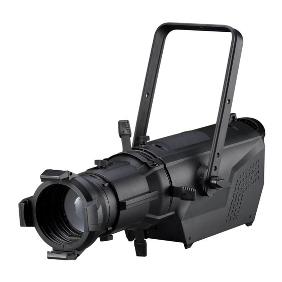
3. The Unit Construction 1. Lens Module; 2. Framing System; 3. Bracket; 4. Main Body; 5. Clip for Gel Holder 6. Gobo Slot 4. Installation Loosen the two screws on the Main Body (MB) and put the Framing System into the MB, then turn the Framing System right .Tighten the two screws to fix the Framing System. -
Page 8: Control Panel
Put the Lens Module into the Framing System and tighten the Lens Module into the Framing System with two screws. 5. Control Panel... -
Page 9: Main Function
1.Display: To show the various menus and the selected functions. 2.Dimmer Adjust Knob:Adjust the lightness for the unit; 3.LED: MASTER Master Mode SLAVE Slave Mode DMX input present 4.MAINS OUT: PowerCon loop connection for main power supply to the next unit; 5.MAINS IN: PowerCon connection from main power supply;... - Page 10 The main functions are shown below:...
- Page 11 DMX Address To select the DMX Address, press the ENTER button to show DMX ADDRESS on the display. Use the DOWN/UP button to adjust the address from 1 to 512. Once the address has been selected, press the ENTER button to setup, to go back to the functions without any changes press the MENU button again.
- Page 12 Mode 1(Optically Linear): The increase in light intensity appears to be linear as DMX value is increased. Mode 2(Square Law): Light intensity control is finer at low levels and coarser at high levels. Mode 3(Inverse Square Law): Light intensity control is coarser at low levels and finger at high levels. Mode 4(S-cure): Light intensity control is finger at low levels and high levels and coarser at medium levels.
- Page 13 To select the Display Setting, press the ENTER button to confirm. Use the DOWN/UP button to select Backlight Intensity , Contrast Ratio, Backlight Auto Off, Display Inverse or Language. Backlight Intensity Select Backlight Intensity, press ENTER button to confirm, present mode will blink on the display, use UP and DOWN button to adjust backlight intensity from 1 (dark) to 10 (bright), press ENTER button to store.
- Page 14 Manual Mode To select the Manual Mode, press the ENTER button to show the MANUAL Mode on the display. Use the DOWN/UP button to select the Strobe/Dimmer Value/Red/Green/ Blue/ Grass Green/ or Amber. Once the function or color has been selected, press the ENTER button to setup, use the DOWN and UP button to change the value (0~255).
-
Page 15: How To Control The Unit
To select the Factory Setting, press the ENTER button to show FACTORY SETTING on the display, use the DOWN/UP button to select No (keep the present setting) or Yes (the fixture will reset to factory settings and exit menu mode). To go back to the functions without any changes press the MENU button again. -
Page 16: Dmx Address Setting
very high-speed signal. Inadequate or damaged cables, soldered joints or corroded connectors can easily distort the signal and shut down the system. 3. The DMX output and input connectors are pass-through to maintain the DMX circuit, when one of the units’ power is disconnected. 4. -
Page 17: Dmx Configuration
7.3 DMX Configuration 5 Channel Mode: CHANNEL VALUE FUNCTION 0 – 255 0% ~ 100% GREEN 0 – 255 0% ~ 100% BLUE 0 – 255 0% ~ 100% GRASSGREEN 0 – 255 0% ~ 100% AMBER 0 – 255 0% ~ 100% 9 Channel Mode:... -
Page 18: Troubleshooting
GRASSGREEN 0 – 255 0% ~ 100% AMBER 0 – 255 0% ~ 100% COLOR 0 – 255 32 Color 000-007 No Function 008-255 8. Troubleshooting Following are a few common problems that may occur during operation. Here are some suggestions for easy troubleshooting: A. -
Page 19: Fixture Cleaning
3. Make sure the fixture is not set into Blackout mode 9. Fixture Cleaning The cleaning of external must be carried out periodically to optimize light output. Cleaning frequency depends on the environment in which the fixture operates: damp, smoky or particularly dirty surrounding can cause greater accumulation of dirt on the fixture’s optics. - Page 20 Declaration of Conformity We declare that our products (lighting equipments) comply with the following specification and bears CE mark in accordance with the provision of the Electromagnetic Compatibility (EMC) Directive 89/336/EEC. EN55103-1: 2009+A1:2012; EN55103-2: 2009; EN61000-3-2: 2014; EN61000-3-3: 2013. & Harmonized Standard EN 60598-1:2015;...
Need help?
Do you have a question about the E-200 MB MC and is the answer not in the manual?
Questions and answers