Advertisement
Quick Links
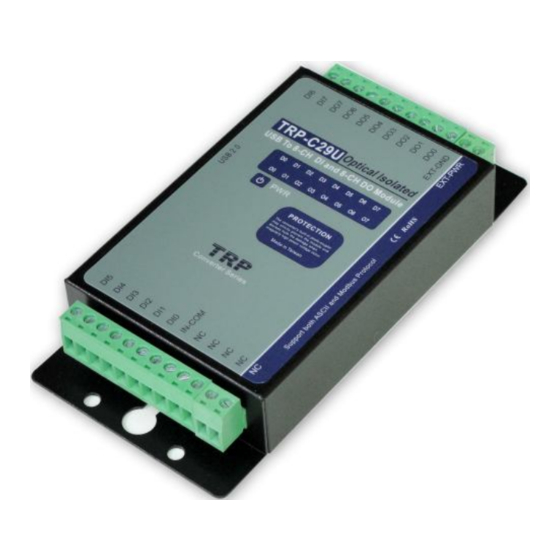
TRP-C29U
8-channel isolated digital input and 8-channel isolated digital
output(O.C) USB serial interface module, Support ASCII and
Modbus Protocol.
User's Manual
Printed Dec. 2010 Rev 1.2
Trycom Technology Co.,Ltd
1F, No.2-11,Sihu street ,Yingge Township, Taipei, Taiwan ROC
Tel: 886-2-86781191 , Fax: 886-2-86781172
www.trycom.com.tw
Copyright
Copyright Notice: The information in this manual is subject to change without prior notice in order to improve reliability, design and function and
dosed not represent a commitment on the part of the manufacturer. No part of this manual may be reproduced, copied, or transmitted in any form
without the prior written permission of manufacturer. Acknowledgment Products mentioned in this manual are mentioned for identification purpose
only. Products manes appearing in this manual may or may not be registered trademarks or copyright of their respective companies.
Advertisement

Subscribe to Our Youtube Channel
Summary of Contents for Trycom Technology TRP-C29U
- Page 1 8-channel isolated digital input and 8-channel isolated digital output(O.C) USB serial interface module, Support ASCII and Modbus Protocol. User’s Manual Printed Dec. 2010 Rev 1.2 Trycom Technology Co.,Ltd 1F, No.2-11,Sihu street ,Yingge Township, Taipei, Taiwan ROC Tel: 886-2-86781191 , Fax: 886-2-86781172 www.trycom.com.tw Copyright Copyright Notice: The information in this manual is subject to change without prior notice in order to improve reliability, design and function and dosed not represent a commitment on the part of the manufacturer.
- Page 2 1.Introduction TRP-C29U is USB to serial interface that provides with 8 optical isolated digital input channels and 8-channel digital output open collector. All channel features screw terminals for convenient connection of field signals as well as LED’s to indicate channel status. Input channels are equipped with 3750Vms DC isolation .
- Page 3 1-4.Block Diagram...
-
Page 4: Pin Definitions
1-5. Pin Definitions Digital Input CH 5 Digital Input CH 6 Digital Input CH 4 Digital Input CH 7 Digital Input CH 3 Open Collector output CH7 Digital Input CH 2 Open Collector output CH6 Digital Input CH 1 Open Collector output CH5 Digital Input CH 0 Open Collector output CH4 IN_COM... - Page 5 2-2. Wire Connection 3. USB to serial Driver Install...
- Page 6 *Notice: When you finished the TRP-C29U USB to serial driver install, the O.S will detect dual serial ports. For TRP-C29U there only one set of serial port can be use and the other one set of serial port is non-function 1.
- Page 7 3-1-1.TRP-C29U Device Installation & Detection: Connect TRP-C29U to the USB Host controller of the PC using a USB cable. The first time you plug-in the cable into the USB port, Windows will start installing the device driver software. You can see the installation status at the pop-up message of system tray.
- Page 8 will find “MosChip High-Speed USB Serial Port (ComX)” under the category Ports (COM & LPT). Here ‘X’ in ‘ComX’ represents the serial port number. You can see the same in the figure below. 3-2 .Install XP driver Find MSSetup.exe and MSUninst.exe which in the folders for Win XP/2K and Win98/ME operation system.
- Page 9 Use “MSSetup.exe” utility to install the driver. Double click on the utility to start the installation process. Press “Install” button to install the drivers for High-Speed USB Multi serial Device. During the installation process, a warning message will popup informing the user that the software being used has not passed the Windows Logo testing.
- Page 10 The utility will display a message stating “Installation completed”. Use “Exit” button to complete the driver installation. Connect TRP-C29U to the USB Host controller of the PC by using a USB cable. The first time you plug the adapter into the USB port, Windows will bring up the "Found New Hardware Wizard"...
- Page 11 As specified in earlier section, a warning message will popup informing the user that the software being used has not passed the Windows Logo testing. You can ignore the warning message by clicking on the option “Continue Anyway”.
- Page 12 The following window conveys that the OS had finished the software installation for “High-Speed USB Multi Serial Compound Device”. Click on “Finish” to complete found new hardware wizard.
- Page 13 Follow the same steps as explained for “High-Speed USB Multi Serial Compound Device” for the second port installation . Select the option “Install the software automatically”…… “Continue Anyway”⋯⋯...
- Page 14 The following wizard indicates that the OS has completed installing the software for the first serial port. Continue the same process for installing the rest of the serial ports.
- Page 15 TRP-C29U device detection can be confirmed by checking the Device manager. Check for “High- Speed USB Multi Serial Compound Device” under Universal Serial Bus Controllers and “High- Speed USB Serial Port (Com X)” under the category Ports (COM & LPT) Now the TRP-C29U Device is ready to use.
- Page 16 “Remove” option. This will remove the MCSTRP-C29U device driver from the PC. The TRP-C29U device driver can be un-loaded through “Device Manager” as well. Go to Device Manager, Select High-Speed USB Multi Serial Compound Device from the Universal serial Bus...
- Page 17 The OS will prompt the user whether to uninstall the device from the system. Click on “OK” to uninstall or “Cancel” to terminate the un-installation. The Win2K software Installation, Detection and Un-Installation procedures are same as Win XP OS process. The only difference being, there is no need of user intervention during the detection of MCSTRP-C29U.
-
Page 18: System Configuration Switch
4. System Configuration Switch The TRP-C29U support the Modbus RTU and ASCII communication protocol, It has a two pins external dip-switch that allow user to select protocol between Modbus/RTU and ASCII. The dip- switch also provides “back to default” function when user forget the configuring information stored in EEPROM such as ID (RS-485 Module address), baud rate and data format. -
Page 19: Function Description
5. Function description Power on mode: When power fail, system reset or host watchdog timeout will cause the module reboot then into power on mode, the module’s digital output value will return to the before setting. And module can accept the host’s command to change the digital output value. Dual Watchdog: Module self watchdog: The module’s watchdog is a hardware reset circuit while working in harsh or noisy environment, the module may be down by the external, The circuit may let the module to work continues and never halt. -
Page 20: Command List
Read digital input latched See 8-9 $IDC(CHK)(cr) Clear digital input latched See 8-10 $ID6(CHK)(cr) Read digital input/output status See 8-11 $ID2(CHK)(cr) Read the TRP-C29U configuration See 8-12 $IDRS(CHK)(cr) Reset See 8-13 $IDM(CHK)(cr) Read the module’s name See 8-14 $IDF(CHK)(cr) Read the module’s firmware version... - Page 21 8-1. Configure TRP-C29U Command %IDNNPPBBDD(CHK)(cr) First leading code Syntax Address of setting module 00-FF(HEX) Description New address of setting from 00-FF(HEX) The Digital I/O module type define to 40 Set new baud rate (See 8-2) Data format (See 8-3) Checksum...
- Page 22 Example: Send command:”%000340054” New ID=“03”,Bard-Rate=“4800”,Checksum=“Enable”,Response:”!03”. Example: Send command:”%0101400601” New ID=“01”,Bard-Rate=“9600”,Checksum=“Disable”, Counter mode=hex,Response:”!01” Then send “#010”……read counter value Response: !01001B””…..counter value=1B(HEX) 8-4. Digital output data Command #IDPPDD(CHK)(cr) First leading code Syntax Address of setting module 00-FF(HEX) Description Output command parameter:00,0A Multi-channel :1L:Single channel (L=0~F) DD: send the data from 00~FF output Checksum...
- Page 23 *Single-Channel mode( Output control for one BIT) Example: Send command:”#011001”….. Data=”01”:DO0=“1”. Response:”>”……. Command valid. Send command:”#011201”….. Data=“01”:DO2=“1”. Response:”>”……. Command valid. Send command:#011700……Data=“00”:DO7=“0”. Response:”>”……..Command valid. *1:Digital output enable,0:digital output disable. 8-5. Read digital input N channel counter value Example: Send command:”#012”…..Read the TRP-C29UM channel 2 counter value. Response:”!0100023”…..The digital input have been trigger 23 times.
- Page 24 Command #IDCN(CHK)(cr) First leading code Syntax Address of setting module 00~FF(HEX) Description Clear N channel counter value to 0 N=0-7 *Channel DI0~DI7 digital input Checksum (cr) Carriage return Response !ID(CHK)(cr) Parameter invalid ?ID(CHK)(cr) Command Invalid Example: Send command:”#01C2”, Clear CH2 counter value to 0. Response:”!01”.
- Page 25 Example: Send command ”#01CS”, Save DI0-DI7 counters value to EEPROM. Response:”!01”. Then after power fail or reset Send command:”#010”……..Read DI0 counter value. Response:”!0100187”………..Last time save value is “187”. 8-9.Read digital input latched Command #IDLS(CHK)(cr) First leading code Syntax Address of setting module 00~FF(HEX) Description Read digital input latch S=0 Latch logic 0...
- Page 26 Read digital /output status Checksum (cr) Carriage return Response !IDABCD(CHK) AB:DO0~DO7 output status ,CD::DI0~DI7 output status (cr) ?ID(CHK)(cr) Command Invalid Example: Send command:$016…….Read digital I/O status . Response:”!0121CF”…….”21”: Output DO0,DO5 enable. “ CF”: Input DI4,DI5 enable. 8-12.Read the TRP-C29U configuration...
- Page 27 Response:”! 01400603”……. DIO type=40,Baud-Rate=9600 (See 7.2) ,Data format=03 Input counter :rising ,Checksum= disable, Model=3….TRP-C29UM. 8-13.Reset Command $IDRS(CHK)(cr) First leading code Syntax Address of setting module 00~FF(HEX) Description Reset the TRP-C29U module Checksum (cr) Carriage return Response !ID(CHK)(cr) Command valid ?ID(CHK)(cr) Command Invalid Example: Send command:”$01RS”…….Reset TRP-C29UM.
- Page 28 Example: Send command:$01M…Read the TRP-C29UM’s name. Response:”!01TRPC29……. The module’s name is “TRPC29. 8-15.Read the module’s firmware version $IDF(CHK)(cr) First Leading code Address of setting module 00-FF(HEX) Syntax Command for leading module’s version Checksum description (cr) Carriage return Response !IDMODYYMMDD Mod: The module type YY: Year MM: Month DD: Date...
- Page 29 Example: Send command:$015…Read the TRP-C29UM’s reset state . Response:”!011”……. The TRP-C29UM has been reset. *If the module is system halt or detect abnormal voltage, the module will restart and reset the flag to “1”. 8-17.Change the module’s name Example: Send command:”~01OABCDE”….. Change the TRP-C29UM’s name become to “ABCDE”. Response:”!01”…….
- Page 30 Command ~IDLEDA(CHK)(cr) First Leading code Address of setting module 00-FF(HEX) Syntax A=0 Turn on all LED when DIO enable off. A=1 Turn off all LED when DIO enable on. description Checksum (cr) Carriage return Response !IDON/OFF Command valid ?ID(CHK)(cr) Command invalid Example: Send command:”~01LED0”…..
- Page 31 Example: Send Command:”~01WD”….. Watchdog disable!. Response:”!01”……. . Command valid, System LED will stop flashing!. 8-21. Read watchdog timeout value Example: Send Command:”~01WR”…. Read watchdog timeout value. Response:” !01WD0F”……. . Command valid, set the watchdog timeout is “0F”..1.6 Sec. 8-22.System stand by (Host OK!)
- Page 32 *If watchdog is in enable , send the Host Ok!”command before watchdog timeout (B) the watchdog will re-count, PWR LED will flashing after watchdog timeout. 8-23.Read power on/safe value Command ~ID4V(CHK)(cr) First Leading code Address of setting module 00-FF(HEX) Syntax Read power on or safe mode I/O status description V=P: Power on mode I/O status...
- Page 33 8-24. Save current digital output status to power on or safe mode Example: Send Command:”#010013”…set up digital output CH7~CH0” to “0001 0011” Response:” !01”……. . Command valid! Then Send Command :” ~015P”….Set the power on mode ,After power fail or reset , The module will load current DO status.
- Page 34 Example: Send Command:”#**”……….Save current digital IO status( All modules on line). Then send command:”$014”…. Read synchronized data Response:”!1010E00”….”1”:Have been send the “#**,the DIO status valid is “010E” *After Read *synchronized data ,A value is”1”, Read again become to ”0”. 9. Modbus/RTU Command Description...
- Page 35 The TRP-C29U support Modbus/RTU protocol, The serial communication data format is Start bit: 1 Data bit: 8 Parity check: None Stop bit: 1 Baud-rate: 1200bps~115200bps. 9-1. Modbus Syntax: Command Format :ID(HEX)+FC(HEX)+SU(HEX)+DA(HEX) or RC(HEX)+CRC16(HEX). Response Format : ID(HEX)+FC(HEX)+SU(HEX)+DA(HEX) or RC(HEX)+CRC16(HEX). Error Format: ID(HEX)+ FC(HEX)+ CRC16(HEX).
- Page 36 Command List Function Description Index ID 46 00 00 (CRC) Read the module’s name 10-1 ID 46 04 IP 00 00 00 (CRC) Set up the module’s address 10-2 ID 46 05 00 (CRC) Read the module’s configuration 10-3 ID 46 06 00 BD 00 00 00 00 00 00 (CRC) Set up the module’s configuration 10-4 ID 46 07 00 (CRC)
- Page 37 0C 29 :Module’s Name is C29 ID C6 00(CRC) ID C6 (CRC) C6:Function Code 00: Reserved code EX: Send Command:”01 46 00 00”…….Read the TRP-C29U’s name Response:”01 46 00 00 0C 29 00 “……Module’s name is C29 Error Response: “01 C6 00”……Error code 10-2.Set up the module’s address...
- Page 38 ID C6 (CRC) C6:Function Code 00: Reserved code Example: Send Command:”01 46 06 00 0A 00 00 00 00 00 00”…….Set up TRP-C29U’s configuration. Response:”01 46 06 00 00 00 00 00 00 00 00 “…Set up OK!. Error Response: “01 C6 00”……Error code.
- Page 39 ID C6 00 (CRC) ID C6 (CRC) C6:Function Code 00: Reserved code Example: Send Command:”01 46 07 00”…….Set up TRP-C29U’s configuration. Response:”01 46 07 09 07 03 00“…JUY. 03.2009 TRP-C29U Firmware Version. Error Response: “01 C6 00”……Error code. 10-6.Read module reset status Command...
- Page 40 00 ID 46 0B 00 ……Command valid ID C6 00 (CRC) ID C6 (CRC) C6:Function Code 00: Reserved code Example: Send Command:”01 46 0B 05 00”…….Set up TRP-C29U’s watchdog timer=500ms. Response:”01 46 0B 00“… Command valid Error Response: “01 C6 00”……Error code.
- Page 41 WT: Watchdog Timer Value ID C6 00 (CRC) ID C6 (CRC) C6:Function Code 00: Reserved code Example: Send Command:”01 46 0C 00”…Read TRP-C29U’s watchdog value. Response:”01 46 0C 01 0F. Error Response: “01 C6 00”…Error code. 10-10.Set up LED panel status...
- Page 42 ID C6 00 (CRC) ID C6 (CRC) C6:Function Code 00: Reserved code Example: Send Command:”01 46 27 01 00”…….Set up TRP-C29U’s power on value. Response:”01 46 27 00“…Command valid. Error Response: “01 C6 00”……Error code. Then send “01 46 09 00” ……..After reset will get power on DD value 10-12.Read power on mode value...
- Page 43 ID C6 00 (CRC) ID C6 (CRC) C6:Function Code 00: Reserved code Example: Send Command:”01 46 29 14 00”…….Set up TRP-C29U’s safe mode value. Response:”01 46 29 00”. Then send “01 46 0B 12 00”……Waiting the watchdog timeout until the digital output value become “14”.
- Page 44 Send Command:”01 46 2A 00”…….Read TRP-C24’s safe mode value. Response:”01 46 2A 12 “…Safe mode value is “12 ”. Error Response: “01 C6 00”……Error code. 10-15. System stand by (Host OK!) Command ID 46 2F 00 (CRC) Address of setting module 1~247 Syntax Function Code Description...
- Page 45 ID 85 ER (CRC) ID 85 :Error Code ER=00 Syntax error ER=01 Data Format error ER=02 Start channel error ER=03 I/O out of range *Set up Single-Channel mode (Output control for 1 Bit). Example: Send command :” 01 05 00 03 FF 00 ”…...Set up the DO3 on. Response:”01 05 00 03 FF 00 ”…..
- Page 46 10-17.Read digital input/output status Command ID 01 00 SS 00 08 (CRC) Address of setting module 1~247 Syntax Function Code Description Start channel number SS=00 Read DO status SS=20 Read DI status SS=40 Latch low SS=60 Latch High 00 08 Output channel number Response ID 01 BC DD (CRC)
- Page 47 10-18. Read digital input counter value Command ID 03 00 SS 00 NN (CRC) Address of setting module 1~247 Syntax Function Code Description 00 SS Start channel number SS=00 00 NN Channel number NN=01~08 Response ID 03 BC DATA (CRC) ID 03 ……Module command Line BC: Byte Counter ,Each channel 2byte DATA :Channel counter value...
- Page 48 Command ID 0F SS NN 00 CN BC 00 (CRC) Address of setting module 1~247 Syntax Function Code Description SS=00 Digital Output SS=02 Clear Counter value SS=03 Save Counter value to EEPROM Start channel number NN=00~07 00 CN Channel number 1~8 Byte Counter=01 Output value Response...
- Page 49 The TRPCOM utility can help you to test and configuration the module’s data transmit and receive digital input and output communication status. User may download TRPCOM software from TRYCOM web www.trycom.com.tw. 1.The “Setting”function is for user to initiate the software to set the Com Port from 1 to 20 and setting the Baud-Rate from 1200 to 115200,Checksum Enable or Disable.
- Page 50 Figure 2 If you don’t know the module’s ID may select “Scan” to find the module’s setting.
- Page 51 Figure 3 Select the module which one you want setting then click “Configuration”. Example: TRP-C29 Configuration A: Get Counter Value please click Digital Input “D0~D7” button. B: Enable the digital output click Digital Output “D0~D7”button. C: Set up new RS485 ID, Baud-Rate and data format then click “Write to EEPROM” button.
- Page 52 12. Application...
Need help?
Do you have a question about the TRP-C29U and is the answer not in the manual?
Questions and answers