HANGCHA Mini Series Operation And Maintenance Manual
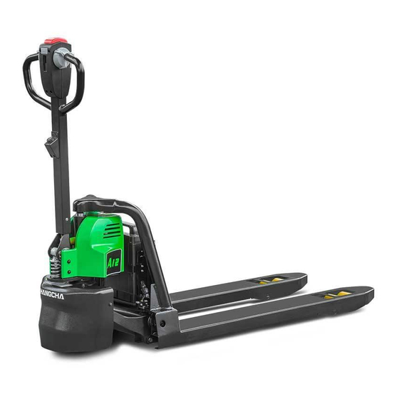
Electric pallet truck
Hide thumbs
Also See for Mini Series:
- Operation and maintenance manua (71 pages) ,
- Operation and maintenance manual (98 pages)


Need help?
Do you have a question about the Mini Series and is the answer not in the manual?
Questions and answers