
Related Manuals for Atlanta Attachment Company 3200M


Summary of Contents for Atlanta Attachment Company 3200M
- Page 1 3200M Model Revision 3.1 Updated Jan 22, 2013 Technical Manual & Parts Lists Atlanta Attachment Company 362 Industrial Park Drive Lawrenceville, GA 30046 770-963-7369 • www.atlatt.com...
- Page 3 Attachment Company. In addition to any confidentiality and non-disclosure obligations that currently exist between you and Atlanta Attachment Company, your use of these materials serves as an acknowledgment of the confidential and proprietary nature of these materials and your duty not to make any unauthorized use or disclosure of these materials.
-
Page 4: Table Of Contents
32007800A Secondary Gripper Assembly ....................39 32007300 Indexing Tray Assembly ......................40 32007700P Roll Holder Assembly ......................41 32009200 Control System......................... 43 3200040 Embroidery Module ........................45 3200058 Lead-in Guide Assembly ......................47 3200M-PD Pneumatic Diagram ........................ 48 3200M-WD Wiring Diagram ........................49... -
Page 5: Important Safety Instruction
Mandatory Information All persons operating and/or working on the 3200M Automatic Border Monogram Workstation should read and understand all parts of the Safety Instructions. This applies, in particular, for persons who only operate and/or work on the unit occasionally (e.g. for maintenance and repair). Persons who have difficulty reading must receive particularly thorough instruction. -
Page 6: Liability
Technical Manual & Parts Lists Liability The machine should only be operated when in perfect working order, with due regard for safety and the potential dangers, as well as in accordance with the Instruction Material. Faults and malfunctions capable of impairing safety should be remedied immediately. We cannot accept any liability for personal injury or property damage due to operator errors or non-compliance with the safety instructions contained in this booklet. -
Page 7: Safety Equipment On The Machines
Technical Manual & Parts Lists A Word to the Operator The greatest danger inherent in our machines: is that of fingers, hands or loose clothing being drawn into a machine by live, coasting or rotating tools or assemblies or of being cut by sharp tools or burned by hot elements. LWAYS BE CONSCIOUS OF THESE DANGERS Safety Equipment on the Machines All machines are delivered with safety equipment, which shall not be removed or... -
Page 8: Protective Eyewear
Technical Manual & Parts Lists Protective Eyewear Protective eyewear that has been tested by the local authorities should be worn whenever there is a possibility of loose or flying objects or particles such as when cleaning the machine with compressed air. Tools Always count the number of tools in your possession before starting work on the machine. -
Page 9: Important Notices
Technical Manual & Parts Lists Important Notices Reporting and Fighting Fires Read the instructions posted in the factory with regard to reporting fires and the emergency exits. Make sure you know exactly where the fire extinguishers and sprinkler systems are located and how they are operated. - Page 10 Technical Manual & Parts Lists - Kinetic energy - Note that some motors or spindles, for example, may continue to run or coast run on after being switched off. - Potential energy - Individual assemblies may need to be secured if necessary for repair work. Delivery of the Machine/Packaging Note any markings on the packaging, such as weights, lifting points and special information.
-
Page 11: Maintenance
Technical Manual & Parts Lists Protect against influences from the surroundings: no structure-borne vibrations, no grinding dust, or chemical vapors. Protect against unauthorized access. Ensure that the machine and accessories are set up in a stable position. Ensure easy access for operation and maintenance (Instruction Manual and layout diagram); also verify that the floor is strong enough to carry the weight of the machine. -
Page 12: Repair
Technical Manual & Parts Lists Repair Replacement Parts We cannot accept any liability whatsoever for damage due to the use of parts made by other manufacturers or due to unqualified repair or modification of the machine. Repair, Electrical The power supply must be switched off (master switch off) and secured so that it cannot be switched on again inadvertently before starting any work on live parts. -
Page 13: A Word To The End User
Technical Manual & Parts Lists A Word to the End User The end user has sole responsibility to enforce the use of safety procedures and guards on the machine. Any other safety devices or procedures due to local regulations should be should be retrofitted in accordance to these regulations and/or the EC Directive on the safety of machines. - Page 14 Technical Manual & Parts Lists...
-
Page 15: Assembly Drawings & Parts Lists
Company. In addition to any confidentiality and non-disclosure obligations that currently exist between you and Atlanta Attachment Company, your use of these materials serves as an acknowledgment of the confidential and proprietary nature of these materials and your duty not to make any unauthorized use or... - Page 16 Technical Manual & Parts Lists...
-
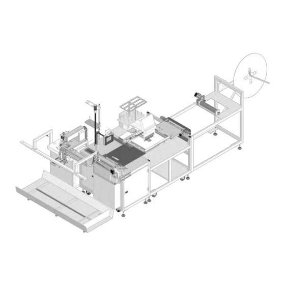
Page 17: 33200M Border Workstation
Page 37 32007600P Transport Assy Page Page 41 32007700P Roll Holder Assy Page Page 43 32009200 Control Panel Page Page 48 3200M-PD Pneumatic Diagram Page Page 49 3200M-WD Wiring Diagram Page 84-2015 Spacer NNH8-32 Hex Nut NNK1/4-20 Kep Nut SSFC90032... - Page 18 Technical Manual & Parts Lists...
-
Page 19: 3200044 Main Frame Assembly
Technical Manual & Parts Lists 3200044 Main Frame Assembly AAC Drawing Number 3200044 Rev 0 QTY PART # DESCRIPTION 0411-1063 ROD, THREADED, 5/8-11 X 5 Page 16 1278-6010 START/STOP BUTTON ASSY 26151 TOOL TRAY, 1X3.5X9 28201 CROSS BLOCK, LARGE 28203 ROD, STRAIGHT, 3/4X11"... -
Page 20: 1278-6010 Start / Stop Button Assembly
Technical Manual & Parts Lists 1278-6010 Start / Stop Button Assembly AAC Drawing Number 191058B Rev 3 QTY PART # DESCRIPTION EEPCB65GM ENCLOSURE MODIF. EEPMTS44 E-STOP BUTTON EEPF3 START BUTTON EEA3L MOUNTING LATCH EE3X01 CONTACT BLOCK N.C. EE3X10 CONTACT BLOCK N.O. EE15Y LEGEND PLATE FF3210... -
Page 21: 3200059 Guillotine Guide Assembly
Technical Manual & Parts Lists 3200059 Guillotine Guide Assembly AAC Drawing Number 3200059 Rev 1 NO. QTY PART # DESCRIPTION NO. QTY PART # DESCRIPTION 011-039 SPROCKET, 18 TEETH SSFC80024 #6-32 X 3/8 FLAT ALLEN 3200019 TOP PLATE, GUIDE ASSY SSHC01048 1/4-20 X 3/4 HEX HEAD 3200021... -
Page 22: 32007200P Panel Support Assembly
Technical Manual & Parts Lists 32007200P Panel Support Assembly AAC Drawing Number 192090A Rev0 QTY PART # DESCRIPTION WWL1/4 Lock Washer 32005018 Rod Mount 32005019 Rod, 1/2 x 17 32007224 Support Plate 32007226 Rod, 1/2 x 12 97-6280 Slide Body 97-6282 Floating Nut 97-6290... -
Page 23: 1278-6160C Dual Foot Pedal Assembly
Technical Manual & Parts Lists 1278-6160C Dual Foot Pedal Assembly AAC Drawing Number 191152B Rev6 QTY PART # DESCRIPTION NNK6-32 Kep Nut 1278-5275 Label 1278-6161 Foot Switch 12788-502A Cable AAF1/8 Clamp SSFC80024 Screw, Flat Allen 1278-5051A Foot Pedal Plate SSFC80016 Screw, Flat Allen... - Page 24 Technical Manual & Parts Lists...
-
Page 25: 32004000Pa Guillotine Assembly
Technical Manual & Parts Lists 32004000PA Guillotine Assembly AAC Drawing Number 192085A Rev1 NO. QTY PART # DESCRIPTION NO. QTY PART # DESCRIPTION AAC7DP-1 Air Cylinder SSFC95032 Screw, Flat Allen AAFCT-7 Clevis SSFC98040 Screw, Flat Allen BBAW-5Z Rod End Bearing SSSC01048 Screw, Socket Cap 33004014... - Page 26 Technical Manual & Parts Lists...
-
Page 27: 32004100 Primary Gripper Assembly
Technical Manual & Parts Lists 32004100 Primary Gripper Assembly AAC Drawing Number 192072A Rev2 QTY PART # DESCRIPTION 1510-09 Bumper 32004101 Lower Clamp 32004104 Gripper Mount 32004105 Mount Brkt 32004106 Upper Clamp 32004107 Gripper Plate 32004109 Cylinder Mount 32004112 Gripper Spacer 32004113 Adapter Block 32004114... - Page 28 Technical Manual & Parts Lists...
-
Page 29: 32005000Pa Prefeed Assembly
Technical Manual & Parts Lists 32005000PA Prefeed Assembly AAC Drawing Number 192086A Rev5 NO. QTY PART # DESCRIPTION NO. QTY PART # DESCRIPTION NNK6-32 Kep Nut 14 WWL1/4 Lock Washer 33005605 Cloth Plate 14 WWFS1/4 Flat Washer Page 27 33005600 Prefeed Roller Assy WWL3/8 Lock Washer... - Page 30 Technical Manual & Parts Lists...
-
Page 31: 33005600 Prefeed Roller Assembly
Technical Manual & Parts Lists 33005600 Prefeed Roller Assembly AAC Drawing Number 192155C Rev7 QTY PART # DESCRIPTION 33005652 Roller Puller 33005610 Left Arm Puller 33005611 33005617 Pivot Mtg Bar 33005622 Prefeed Brace 33005675 Roller Arm Assy 33005632 Roller 33005653 Seam Detect Arm 33005671 Roller... - Page 32 Technical Manual & Parts Lists...
-
Page 33: 33005650A Puller Assembly
Technical Manual & Parts Lists 33005650A Puller Assembly AAC Drawing Number 192913B Rev7 QTY PART # DESCRIPTION 33004080 Encoder Support Brkt 33005674 Motor Mnt Brkt 0411-016 Nut Plate 33005681 Encoder Guard 33005603C Pulller Roller 33005608 Bearing Block 33005609 Bearing Mnt Plate EENC256 Encoder 4059-DC1500A... - Page 34 Technical Manual & Parts Lists...
-
Page 35: 32006500A Closer Station Assembly
Technical Manual & Parts Lists 32006500A Closer Station Assembly AAC Drawing Number 192936C Rev4 NO. QTY PART # DESCRIPTION NO. QTY PART # DESCRIPTION 12 WWL1/4 Lock Washer SSZS93032 Screw, Sheet Metal Page 19 1278-6160C Foot Pedal Assy 12 SSSC98064 Screw, Socket Cap Page SSSC01048... - Page 36 Technical Manual & Parts Lists...
-
Page 37: 32006600Asew Head Assembly
Technical Manual & Parts Lists 32006600ASew Head Assembly AAC Drawing Number 192685C Rev5 QTY PART # DESCRIPTION 1278-6364 Tape Mnt Disc 1335-316 Bent Rod 32006525 Foot 1918-073 Footlift Link 22100-013A Sync Adapter 23080 Eye Clamp Block 23132A Eye Holder 32006524 Pivot Mnt Brkt 32006527A Oil Tray... - Page 38 Technical Manual & Parts Lists...
-
Page 39: 32007850 Pivot Assembly
Technical Manual & Parts Lists 32007850 Pivot Assembly AAC Drawing Number 32007850 Rev2 NO. QTY PART # DESCRIPTION NO. QTY PART # DESCRIPTION 011-070 PLATE,CYLINDER MOUNT GGD160XL37 BELT,GEAR,DBL. 1975-213 CYLINDER,AIR,DA,9/16B,1/2S IID012X064 DOWEL PIN,3/16 X 1 26179 BUSHING,IDLER,PULLEY MML050 SPIDER, COUPLING 26183 PULLEY MOD, 18XLB037 MML050-375 COUPLING,3/8 BORE... - Page 40 Technical Manual & Parts Lists...
-
Page 41: 32007600P Transport Assembly
Technical Manual & Parts Lists 32007600P Transport Assembly AAC Drawing Number 192087A Rev 5 NO. QTY PART # DESCRIPTION NO. QTY PART # DESCRIPTION 011-020 Stepper Motor MMAGH25CAN Bearing Block 1278-6010A Start/Stop Button MMAGR251430N Linear Rail 32007602 Rail Mount Weldment MML050 Spider 32007605... - Page 42 Technical Manual & Parts Lists...
-
Page 43: 32007800A Secondary Gripper Assembly
Technical Manual & Parts Lists 32007800A Secondary Gripper Assembly AAC Drawing Number 9002088 Rev5 NO. QTY PART # DESCRIPTION NO. QTY PART # DESCRIPTION 32007611 BELT HOLDER MMAGH25CAN LINEAR BEARING 32007622 FLAG,CRASH SWITCH MMAGR25139N RAIL LINEAR AG 32007657 MOUNT, CABLE TRACK MMCPL100 BELT CLAMP 32007801... -
Page 44: 32007300 Indexing Tray Assembly
Technical Manual & Parts Lists 32007300 Indexing Tray Assembly AAC Drawing Number 9002178 Rev5 QTY PART # DESCRIPTION 32007301 TRAY, INDEXING 32007302 PUSHER, INDEXER 32007303 WEAR PAD 32007306 MOUNT, END, FOOT 32007307 MOUNT, CENTER, FOOT AA198RA408U FLOW CONTROL,RC 1/8X1/4 AACSRLM048 CYLINDER,AIR,RODLESS,48ST *18 FT MM100-1/8 DOOR TRIM - BLACK... -
Page 45: 32007700P Roll Holder Assembly
Technical Manual & Parts Lists 32007700P Roll Holder Assembly AAC Drawing Number 192088A Rev1 QTY PART # DESCRIPTION 1961-253A Unwind Hub 784B-2436 Alu Plate WWL3/8 Lock Washer 32007704 Frame 33008202 Rod, 3/4 x 21 WWSQ080B Square Washer MM132-1496 End Cap SSHC25160 Screw, Hex Cap SSFC80032... - Page 46 Technical Manual & Parts Lists...
-
Page 47: 32009200 Control System
FF1724 Strain Relief FF264-341 Terminal Block, Grey FF264-347 Terminal Block, Green FF264-371 Terminal Block End SSPS90024 Screw, Pan Head FFRAV781BW TVS Module TTAA5267 Terminal AR 3200M-WD Wiring Diagram 3200MLAB Label SSSC70024 Screw, Socket Cap AR 3200M-PD Pneumatic Diagram 12788-509 Jumper... - Page 48 Technical Manual & Parts Lists...
-
Page 49: 3200040 Embroidery Module
NO. QTY PART # DESCRIPTION NO. QTY PART # DESCRIPTION 0411-1063 ROD, THREADED, 5/8-11 X 5 WWL5/16 5/16 LW 3200026 CLAMP, LOWER 3200071 BRACKET, EYE MOUNT,3200M 3200027 MOUNT, CLAMP FFSM312LVQ EYE,ELECTRIC,10-30VDC 3200028 WASHER PLATE 1975-412A PLATE,NUT,4-40,.95CTC 3200031 BRACKET, BEARING AAFBP-11C... - Page 50 Technical Manual & Parts Lists...
-
Page 51: 3200058 Lead-In Guide Assembly
Technical Manual & Parts Lists 3200058 Lead-in Guide Assembly AAC Drawing Number 3200058 Rev 1 QTY PART # DESCRIPTION 011-039 SPROCKET, 18 TEETH 3200021 BASE, GUIDE ASSY. 3200041 TOP PLATE 3200042 CYLINDER, MOD. 3200043 PLATE,NUT,6-32@1.181 CTC 33006102 NUT PLATE, #6-40 33006103A GUIDE SUPPORT 33006105... -
Page 52: 3200M-Pd Pneumatic Diagram
Technical Manual & Parts Lists 3200M-PD Pneumatic Diagram 125693C... -
Page 53: 3200M-Wd Wiring Diagram
Technical Manual & Parts Lists 3200M-WD Wiring Diagram 125694C... - Page 54 Atlanta Attachment Company (AAC) Statement of Warranty Manufactured Products Atlanta Attachment Company warrants manufactured products to be free from defects in material and workmanship for a period of eight hundred (800) hours of operation or one hundred (100) days whichever comes first. Atlanta Attachment Company warrants all electrical components of the Serial Bus System to be free from defects in material or workmanship for a period of thirty six (36) months.
- Page 55 Declaración de Garantia Productos Manufacturados Atlanta Attachment Company garantiza que los productos de fabricación son libres de defectos de mate-rial y de mano de obra durante un periodo de ochocientos (800) horas de operación o cien (100) días cual llegue primero.
- Page 56 Atlanta Attachment Company 362 Industrial Park Drive Lawrenceville, GA 30046 770-963-7369 www.atlatt.com Printed in the USA...
Need help?
Do you have a question about the 3200M and is the answer not in the manual?
Questions and answers