
Related Manuals for Atlanta Attachment Company 3200PCA


Summary of Contents for Atlanta Attachment Company 3200PCA
- Page 1 3200PCA-SH Model 3200PCA Model Revision 0 Preliminary Copy June 15, 2023 (wr) Technical Manual & Parts Lists Atlanta Attachment Company 362 Industrial Park Drive Lawrenceville, GA 30046 770-963-7369 • www.atlatt.com...
- Page 3 Company. In addition to any confidentiality and non-disclosure obligations that currently exist between you and Atlanta Attachment Company, your use of these materials serves as an acknowledgment of the confidential and proprietary nature of these materials and your duty not to make any unauthorized use or disclosure of these materials.
-
Page 4: Table Of Contents
Operational Path of Screens ........................... 22 Service: ................................32 Prefeed Motor ..............................32 Feed Motor ..............................33 3200PCA Closer Motor Parameter Settings (Juki) ..................34 Machine Maintenance ............................ 35 Electric Eye Sensor Adjustment ........................35 Reflective Tape Maintenance ........................35... - Page 5 32007700P Roll Holder Assembly ........................ 75 32009000PCA Control System ........................76 4003-500B Thread Break Sensor Assembly ....................77 3200PC-PD Pneumatic Diagram ........................78 3200PCA-WD Wiring Diagram, Control Panel.................... 79 Notes: ................................80 Atlanta Attachment Company (AAC) Statement of Warranty ..............0...
- Page 6 Technical Manual & Parts Lists General Information Symbol Hazard warning sign: General Hazard Hazard warning sign: Electrical hazard, electrical hazard Hazard warning sign: Beware of damage to hands.
-
Page 7: Important Safety Instruction
Technical Manual & Parts Lists Important Safety Instruction This part of the Instruction Material is provided for the safe use of your equipment. It contains important information to help work safely with the unit and describes the dangers inherent in machinery. Some of these dangers are obvious, while others are less evident. Mandatory Information All persons operating and/or working on the 3200PC Auto border W/ Label INS. -
Page 8: Liability
Technical Manual & Parts Lists Liability The machine should only be operated when in perfect working order, with due regard for safety and the potential dangers, as well as in accordance with the Instruction Material. Faults and malfunctions capable of impairing safety should be remedied immediately. -
Page 9: Safety Equipment On The Machines
Technical Manual & Parts Lists A Word to the Operator The greatest danger inherent in our machines: is that of fingers, hands or loose clothing being drawn into a machine by live, coasting or rotating tools or assemblies or of being cut by sharp tools or burned by hot elements. LWAYS BE CONSCIOUS OF THESE DANGERS Safety Equipment on the Machines All machines are delivered with safety equipment, which shall not be removed or bypassed... -
Page 10: Protective Eyewear
Technical Manual & Parts Lists Protective Eyewear Protective eyewear that has been tested by the local authorities should be worn whenever there is a possibility of loose or flying objects or particles such as when cleaning the machine with compressed air. Tools Always count the number of tools in your possession before starting work on the machine. -
Page 11: Important Notices
Technical Manual & Parts Lists Important Notices Reporting and Fighting Fires Read the instructions posted in the factory about reporting fires and the emergency exits. Make sure you know exactly where the fire extinguishers and sprinkler systems are located and how they are operated. Pass on the corresponding information to the firemen when they arrive. - Page 12 The packaging and machine must immediately be examined for signs of damage in transit. Such damage must be reported to the shipper/transporter within the applicable time limits. Contact Atlanta Attachment Company and/or your transport insurer immediately, if signs of damage are visible. Never operate a damaged machine.
-
Page 13: Maintenance
Technical Manual & Parts Lists Protect against influences from the surroundings: no structure-borne vibrations, no grinding dust, or chemical vapors. Protect against unauthorized access. Ensure that the machine and accessories are set up in a stable position. Ensure easy access for operation and maintenance (Instruction Manual and layout diagram); also verify that the floor is strong enough to carry the weight of the machine. -
Page 14: Repair
Technical Manual & Parts Lists Repair Replacement Parts We cannot accept any liability whatsoever for damage due to the use of parts made by other manufacturers or due to unqualified repair or modification of the machine. Repair, Electrical The power supply must be switched off (master switch off) and secured so that it cannot be switched on again inadvertently before starting any work on live parts. -
Page 15: A Word To The End User
Technical Manual & Parts Lists A Word to the End User The end user has sole responsibility to enforce the use of safety procedures and guards on the machine. Any other safety devices or procedures due to local regulations should be retrofitted in accordance with these regulations and/or the EC Directive on the safety of machines. -
Page 16: General Machine Data
Technical Manual & Parts Lists General Machine Data Electrical / Pneumatic Setup Electrical: 220 VAC, 15amp, 50/60 Hz Single Phase Pneumatic: 80 PSI, 5 SCFM avg. Set the low-pressure switch to 60 PSI. Sewing Heads: Juki Lockstitch DNU1541-7 Set RPM: 1800 Installation: Initial Machine Setup Position the machine in a desired location on a sound and reasonably level floor. -
Page 17: Component Identification
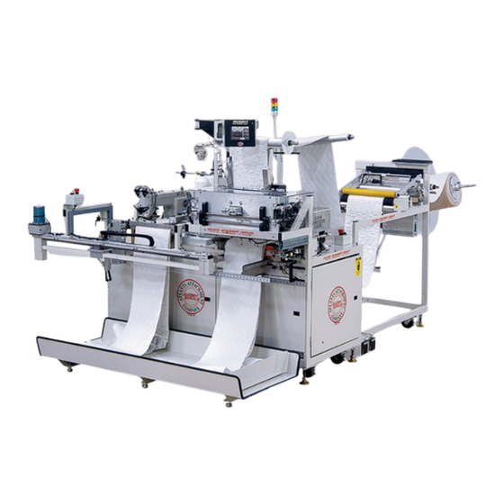
Technical Manual & Parts Lists Component Identification Border Roll Holder Prefeed Drive Rollers Raise Roller Push Button Touch Screen Border Guides Guillotine Power and Air supply hookups. -
Page 18: General Operation
Technical Manual & Parts Lists General Operation: Touch Screen Operation The graphic images presented on the touch screen show “3-dimensional” buttons, which may be pressed to access other screens, change counters and timers, or actuate hardware. Areas lacking the “3 dimensional” border contain information only. -
Page 19: Setup Screen Information
Technical Manual & Parts Lists Setup Screen Information Operator Level view Mechanic level or higher view. Show All Settings: Displays all the values for the different settings in a table format. Show All Styles: Displays all border styles entered in a table format. System Information: Users can view the machine version and serial number, the software revision and controller serial number, and the total piece count. -
Page 20: Border Compensation
Technical Manual & Parts Lists Border Compensation Security Level – Set to Mechanic or above. Press “SETUP” Press “ADVANCE SETUP” Press “COMPENSATION” Take a border and mark 2 lines 300” apart. Insert the border and line up the first mark with knife. Press “FEED COMP. -
Page 21: Using Border Stretch Table To Obtain Current Border Lengths
Technical Manual & Parts Lists Using Border Stretch Table to Obtain Current Border Lengths AAC Drawing Number 261446A Rev 0... -
Page 22: Machine Operation, Operator
Technical Manual & Parts Lists Machine Operation, Operator Turn on the power and select the desired language (if other than English) and wait until the touch screen displays the Ready – New Order screen. Initial Border Loading Procedure Press the Open Rollers button, the Prefeed Roller and the Main Roller lift. -
Page 23: Styles
Security Level – set to Mechanic or above. After all the default border lengths have been recorded, they must be stored in the controller of the 3200PCA machine. To store the default border lengths into a new style, press Setup button on Ready Screen and then press Advanced Styles button. - Page 24 Technical Manual & Parts Lists Edit Styles Option 1 Security Level – set to Mechanic or above for access. There are several ways or paths to access the Edit Styles Menu. Option 1: On the Setup page, press Advanced Styles button to access the Active Style Page screens.
- Page 25 Technical Manual & Parts Lists Edit Styles Option 2 Security Level –set to Mechanic or above for access. There are several ways or paths to access the Edit Styles Menu Option 2: On the Setup Page, press Show All Styles button to access the List of Styles.
- Page 26 Technical Manual & Parts Lists Selecting Styles Security Level – Operator and all levels above To setup the machine to make the desired borders go to the main Ready – New Order screen and press the large Edit Order button. The new screen Edit Order displays all available options: the style and quantity of borders.
-
Page 27: Border Splicing Method
Technical Manual & Parts Lists Border Splicing Method When the machine runs out of border material, it stops and automatically back feeds about 10 inches to make the border splicing easier. The screen displays an “Out of Border Material” message. Load the next border roll on the pin and staple its leading edge to the trailing edge of the border currently in the machine. -
Page 28: Bobbin Handling Method
Light Tower Function The purpose of the 3200PCA light tower is to indicate the operational status of the machine at some distance away from the machine. This makes it easy to see machine status at a glance. Definitions for the different light states currently available on the 3200 are included below. -
Page 29: Operational Path Of Screens
Technical Manual & Parts Lists Operational Path of Screens Security Level – set to Mechanic or above for access Ready Screens Start to Making Borders Screen Reset Screen Language Screen Piece Count Clock Screen... - Page 30 Technical Manual & Parts Lists Ready Screen to Open / Close Rollers Ready Screen to Cut Border Screen Ready Screen – Edit New Order Button Ready Screen to Setu Setup Page 1 Setup Page 1 to Bobbin Monitor...
- Page 31 Technical Manual & Parts Lists Edit Order Menus Single Border Disabled Single Border Enabled Enter Quantity Required. Enter Quantity Required Border Fill Type Settings Foam Fiber Closer Head Activation Enabled Disabled...
- Page 32 Technical Manual & Parts Lists Edit Order Screen to Style Select Menu Edit Order Screen to Style Select Keypad Edit Order Screen to Piece Cut Setup Piece Cut to Piece Quantity Setting Piece Cut Process - Start Button Piece Cut to Piece Length Setting...
- Page 33 Technical Manual & Parts Lists Setup Menus Setup Screen to Show All Settings Edit Sets Setup Screen to Show All Styles Edit Styles Menu...
- Page 34 Technical Manual & Parts Lists Setup to System Information Setup Screen to Manual Setup Screen to Advanced Setup Advanced Setup to Test Cycles Advanced Setup to Compensation Manual Air Pressure Settings Manual Closer Cycle...
- Page 35 Technical Manual & Parts Lists Setup to Security Raise or Lower Security Level Setup to Advanced Settings Page 1 Advanced Settings Page 2 Advanced Settings Page 3 Advanced Settings Page 4...
- Page 36 Technical Manual & Parts Lists Advanced Settings Page 5 Advanced Settings Page 10 Setup Continued Setup to Advanced / Active Styles Page 1 Advanced / Active Style Page 2...
- Page 37 Technical Manual & Parts Lists Setup Screen to Advanced Manual Menu Border Prefeed Border Feed Border Gripping Closer Head System...
- Page 38 Technical Manual & Parts Lists On-Board Diagnostics Typical Example of Error / Warning Pages Help Screens. Accessible by pushing at the top-middle section of a Button. (Examples below)
-
Page 39: Service
Technical Manual & Parts Lists Service: Prefeed Motor Before Programming, Perform a Master Reset of Parameters (See Below) PARAMETER RANGE VALUE DESCRIPTION Mode of operation. MUST SET THIS PARAMETER FIRST! 0-999 Maximum speed when "129" is 0, 1, or 2. Linear acceleration 0-50 Braking power at standstill... -
Page 40: Feed Motor
Technical Manual & Parts Lists Feed Motor Before Programming, Perform a Master Reset of Parameters (See Below) PARAMETER RANGE VALUE DESCRIPTION Mode of operation. MUST SET THIS PARAMETER FIRST! 70-390 Positioning speed = 700 rpm 0-999 Maximum speed = 1200 rpm. Linear acceleration 0-50 Braking power at standstill... -
Page 41: 3200Pca Closer Motor Parameter Settings (Juki)
Technical Manual & Parts Lists 3200PCA Closer Motor Parameter Settings (Juki) 3 DIGIT 4 DIGIT PARAMETER RANGE (default) DESCRIPTION VALUE VALUE 0-24 (5) Mode of operation. MUST SET THIS PARAMETER FIRST! EB301 Treadle Mode (5131F and later pgms only) 0-254 (2) -
Page 42: Machine Maintenance
Technical Manual & Parts Lists Machine Maintenance Regularly scheduled maintenance of the 3200PCA unit reduces possible problems and downtime. Proper care will also ensure a longer life and better performance of the machine. Perform the following procedures to properly maintain the machine. -
Page 43: Assembly Drawings & Parts Lists
Technical Manual & Parts Lists Assembly Drawings & Parts Lists: The materials contained herein are confidential and proprietary information of Atlanta Attachment Company. In addition to any confidentiality and non-disclosure obligations that currently exist between you and Atlanta Attachment Company, your use of these materials serves as an acknowledgment of the confidential and proprietary nature of these materials and your duty not to make any unauthorized use or disclosure of these materials. -
Page 44: 33200Pca-Sh Auto Border
Technical Manual & Parts Lists 33200PCA-SH Auto Border…Narrow Frame Model AAC Drawing Number 90071747 Rev 0... - Page 45 Technical Manual & Parts Lists...
-
Page 46: 3200647 Closer Station
Technical Manual & Parts Lists 3200647 Closer Station AAC Drawing 3200647 Rev 0... -
Page 47: 4300601 Closer Station Generic
Technical Manual & Parts Lists 4300601 Closer Station Generic AAC Drawing Number 4300601 Rev 1... - Page 48 Technical Manual & Parts Lists...
-
Page 49: 3200649 Primary Gripper Assembly
Technical Manual & Parts Lists 3200649 Primary Gripper Assembly AAC Drawing Number 3200649 Rev 0... - Page 50 Technical Manual & Parts Lists...
-
Page 51: 3200664 Small Roll Holder Assembly
Technical Manual & Parts Lists 3200664 Small Roll Holder Assembly AAC Drawing Number 3200664 Rev 0... -
Page 52: 3200615 Roll Holder Assembly, Left
Technical Manual & Parts Lists 3200615 Roll Holder Assembly, Left AAC Drawing Number 3200615 Rev 0... -
Page 53: Notes
Technical Manual & Parts Lists Notes:... -
Page 54: 33200Pca Auto Border
Technical Manual & Parts Lists 33200PCA Auto Border…Measure, Cut and Close AAC Drawing Number 90071467 Rev 0... - Page 55 Technical Manual & Parts Lists...
-
Page 56: 3200085 Small Roll Swing Rod Assembly
Technical Manual & Parts Lists 3200085 Small Roll Swing Rod Assembly AAC Drawing Number 3200085 Rev 0 QTY PART # DESCRIPTION 1961-251A HUB, UNWIND SHAFT 1961-253A HUB, UNWIND STAND 3200092 WELDMENT,MID ROD MOUNT 32005004 ROD,SS,3/4 X 24.0L 360-116 HUB, LOCKING 784-08-050 DISC,BB,SP,8"... -
Page 57: 3200114 Edge Guide Assembly
Technical Manual & Parts Lists 3200114 Edge Guide Assembly AAC Drawing Number 3200114 Rev 0 NO. QTY PART # DESCRIPTION NO. QTY PART # DESCRIPTION 1 3200105 SUPPORT, FIXED GUIDE 1 MM1910A43M RULER,SILVER MYLAR 36" 1 3200107 MOUNT, FIXED GUIDE 4 WWL10 WASHER,LOCK,#10 1 3200108... -
Page 58: 3200190 Closer Carriage Covers
Technical Manual & Parts Lists 3200190 Closer Carriage Covers AAC Drawing Number 3200190 Rev 1... -
Page 59: 3200210 Closer Station
Technical Manual & Parts Lists 3200210 Closer Station AAC Drawing Number 3200210 Rev 1... - Page 60 Technical Manual & Parts Lists...
-
Page 61: 1278-6160C Dual Foot Pedal Assembly
Technical Manual & Parts Lists 1278-6160C Dual Foot Pedal Assembly AAC Drawing Number 191152B Rev 6... -
Page 62: 3200200 Sewing Head Assembly
Technical Manual & Parts Lists 3200200 Sewing Head Assembly AAC Drawing Number 3200200 Rev 0... -
Page 63: 3200195 Feed Conveyor Assembly
Technical Manual & Parts Lists 3200195 Feed Conveyor Assembly AAC Drawing Number 3200195 Rev 3... - Page 64 Technical Manual & Parts Lists...
-
Page 65: 32003000Pc Main Frame Assembly
Technical Manual & Parts Lists 32003000PC Main Frame Assembly AAC Drawing Number 192166A Rev 2... - Page 66 Technical Manual & Parts Lists...
-
Page 67: 32007200Pc Border Support Assembly
Technical Manual & Parts Lists 32007200PC Border Support Assembly AAC Drawing Number 9001289 Rev 0 QTY PART # DESCRIPTION 3300087 BODY,SLIDE 3300088 PLATE,SUPPORT,ROD 3300089 BODY,SLIDE 3300097 MOUNT, BORDER SUPPORT 32005019 ROD, .50 DIA X 17.0 L 97-6282 NUT,FLOATING COUPLING 97-6290 NUT,LOCK,5/8 HEX,1/4-28 AA198RA508 FLOW CONTROL,5/32 X 1/8"... -
Page 68: 32004000Pb Guillotine Assembly
Technical Manual & Parts Lists 32004000PB Guillotine Assembly AAC Drawing Number 192111A Rev 4... - Page 69 Technical Manual & Parts Lists 32004000PB parts list NO. QTY PART # DESCRIPTION NO. QTY PART # DESCRIPTION AAC7DP-1 AIR CYLINDER 3200129 BLOCK, PLATE RUB MNTG AAFCT-7 CLEVIS, AIR CYL. 13 SSBC70016 BUTTON CAP SCREW BBAW-7 ROD END BEARING SSSC98040 SOCKET CAP SCREW 33004014 TOP RIGHT ARM...
-
Page 70: 32004100Pc Primary Gripper Assembly
Technical Manual & Parts Lists 32004100PC Primary Gripper Assembly AAC Drawing Number 9001290 Rev 1... - Page 71 Technical Manual & Parts Lists...
-
Page 72: 32005000Pa Prefeed Roller Assembly
Technical Manual & Parts Lists 32005000PA Prefeed Roller Assembly AAC Drawing Number 192086A Rev 6... - Page 73 Technical Manual & Parts Lists...
-
Page 74: 33005600 Prefeed Roller Assembly
Technical Manual & Parts Lists 33005600 Prefeed Roller Assembly AAC Drawing Number 192155C Rev 8... - Page 75 Technical Manual & Parts Lists...
-
Page 76: 33005650A Bottom Puller Roller Assembly
Technical Manual & Parts Lists 33005650A Bottom Puller Roller Assembly AAC Drawing Number 192913B Rev 3... -
Page 77: 32007300 Indexing Tray Assembly
Technical Manual & Parts Lists 32007300 Indexing Tray Assembly AAC Drawing Number 9002178 Rev 5... -
Page 78: 32007600P Transport Assembly
Technical Manual & Parts Lists 32007600P Transport Assembly AAC Drawing Number 192087A Rev 6... - Page 79 Technical Manual & Parts Lists...
-
Page 80: 32007800A Secondary Gripper Assembly
Technical Manual & Parts Lists 32007800A Secondary Gripper Assembly AAC Drawing Number 9002088 Rev 5... - Page 81 Technical Manual & Parts Lists...
-
Page 82: 32007700P Roll Holder Assembly
Technical Manual & Parts Lists 32007700P Roll Holder Assembly AAC Drawing Number 192088A Rev 1 PART # DESCRIPTION 1961-253A Unwind Hub 784B-2436 Alu Plate WWL3/8 Lock Washer 32007704 Frame 33008202 Rod, 3/4 x 21 WWSQ080B Square Washer MM132-1496 End Cap SSHC25160 Screw, Hex Cap SSFC80032... -
Page 83: 32009000Pca Control System
Technical Manual & Parts Lists 32009000PCA Control System AAC Drawing Number 90071466 Rev 1... -
Page 84: 4003-500B Thread Break Sensor Assembly
Technical Manual & Parts Lists 4003-500B Thread Break Sensor Assembly AAC Drawing Number 9002422 Rev 4... -
Page 85: 3200Pc-Pd Pneumatic Diagram
Technical Manual & Parts Lists 3200PC-PD Pneumatic Diagram 125621B... -
Page 86: 3200Pca-Wd Wiring Diagram, Control Panel
Technical Manual & Parts Lists 3200PCA-WD Wiring Diagram, Control Panel. 125622B... -
Page 87: Notes
Technical Manual & Parts Lists Notes:... -
Page 89: Atlanta Attachment Company (Aac) Statement Of Warranty
(800) hours of operation or one hundred (100) days whichever comes first. Atlanta Attachment Company warrants all electrical components of the Serial Bus System to be free from defects in material or workmanship for a period of thirty-six (36) months. - Page 90 Technical Manual & Parts Lists Productos Manufacturados Atlanta Attachment Company garantiza que los productos de fabricación son libres de defectos de mate-rial y de mano de obra durante un periodo de ochocientos (800) horas de operación o cien (100) días cual llegue primero. Atlanta Attachment Company garantiza que todos los componentes del Serial bus son libres de defectos de material y de mano de obra durante un periodo de treinta y seis (36) meses.
- Page 91 Technical Manual & Parts Lists Atlanta Attachment Company 362 Industrial Park Drive Lawrenceville, GA 30046 770-963-7369 www.atlatt.com Created and Printed in the USA...
Need help?
Do you have a question about the 3200PCA and is the answer not in the manual?
Questions and answers