
Related Manuals for Atlanta Attachment Company 3200PC


Summary of Contents for Atlanta Attachment Company 3200PC
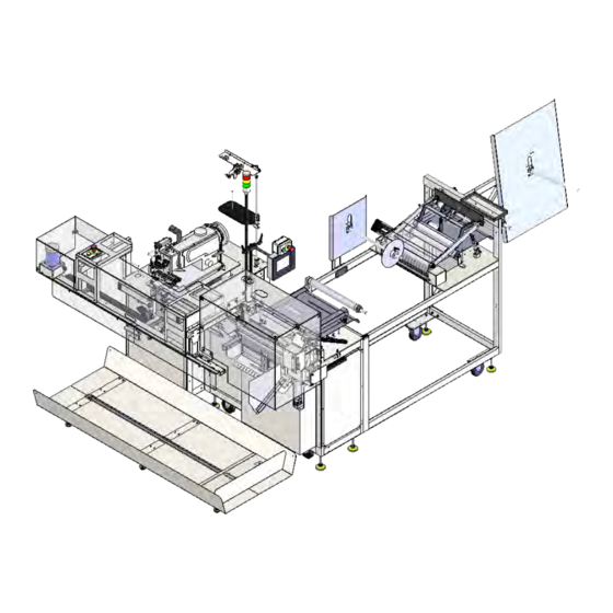
- Page 1 3200PC Model Revision 3.5 Updated Nov 25 , 2015 Technical Manual & Parts Lists Atlanta Attachment Company 362 Industrial Park Drive Lawrenceville, GA 30046 770-963-7369 • www.atlatt.com...
- Page 3 Attachment Company. In addition to any confidentiality and non-disclosure obligations that currently exist between you and Atlanta Attachment Company, your use of these materials serves as an acknowledgment of the confidential and proprietary nature of these materials and your duty not to make any unauthorized use or disclosure of these materials.
-
Page 4: Table Of Contents
Technical Manual & Parts Lists Contents Important Safety Instruction ........................1 Liability ..............................2 Safety Equipment on the Machines ......................3 Protective Eyewear ............................. 4 Important Notices............................5 Maintenance ..............................7 Repair ................................8 A Word to the End User..........................9 Safety Precautions ............................ - Page 5 Technical Manual & Parts Lists 32005000PA Prefeed Roller Assembly ....................44 33005600 Prefeed Roller Assembly ......................46 33005650A Bottom Puller Roller Assembly .................... 48 32006500A Closer Station Assembly ............Error! Bookmark not defined. 1278-6160C Dual Foot Pedal Assembly....................30 32006600ASew Head Assembly ............... Error! Bookmark not defined. 32007850 Pivot Assembly .................
-
Page 6: Important Safety Instruction
Mandatory Information All persons operating and/or working on the 3200PC Auto border W/ Label INS. should read and understand all parts of the Safety Instructions. This applies, in particular, for persons who only operate and/or work on the unit occasionally (e.g. for maintenance and repair). Persons who have difficulty reading must receive particularly thorough instruction. -
Page 7: Liability
Technical Manual & Parts Lists Liability The machine should only be operated when in perfect working order, with due regard for safety and the potential dangers, as well as in accordance with the Instruction Material. Faults and malfunctions capable of impairing safety should be remedied immediately. We cannot accept any liability for personal injury or property damage due to operator errors or non-compliance with the safety instructions contained in this booklet. -
Page 8: Safety Equipment On The Machines
Technical Manual & Parts Lists A Word to the Operator The greatest danger inherent in our machines: is that of fingers, hands or loose clothing being drawn into a machine by live, coasting or rotating tools or assemblies or of being cut by sharp tools or burned by hot elements. LWAYS BE CONSCIOUS OF THESE DANGERS Safety Equipment on the Machines All machines are delivered with safety equipment, which shall not be removed or... -
Page 9: Protective Eyewear
Technical Manual & Parts Lists Protective Eyewear Protective eyewear that has been tested by the local authorities should be worn whenever there is a possibility of loose or flying objects or particles such as when cleaning the machine with compressed air. Tools Always count the number of tools in your possession before starting work on the machine. -
Page 10: Important Notices
Technical Manual & Parts Lists Important Notices Reporting and Fighting Fires Read the instructions posted in the factory with regard to reporting fires and the emergency exits. Make sure you know exactly where the fire extinguishers and sprinkler systems are located and how they are operated. - Page 11 Technical Manual & Parts Lists - Kinetic energy - Note that some motors or spindles, for example, may continue to run or coast run on after being switched off. - Potential energy - Individual assemblies may need to be secured if necessary for repair work. Delivery of the Machine/Packaging Note any markings on the packaging, such as weights, lifting points and special information.
-
Page 12: Maintenance
Technical Manual & Parts Lists Protect against influences from the surroundings: no structure-borne vibrations, no grinding dust, or chemical vapors. Protect against unauthorized access. Ensure that the machine and accessories are set up in a stable position. Ensure easy access for operation and maintenance (Instruction Manual and layout diagram); also verify that the floor is strong enough to carry the weight of the machine. -
Page 13: Repair
Technical Manual & Parts Lists Repair Replacement Parts We cannot accept any liability whatsoever for damage due to the use of parts made by other manufacturers or due to unqualified repair or modification of the machine. Repair, Electrical The power supply must be switched off (master switch off) and secured so that it cannot be switched on again inadvertently before starting any work on live parts. -
Page 14: A Word To The End User
Technical Manual & Parts Lists A Word to the End User The end user has sole responsibility to enforce the use of safety procedures and guards on the machine. Any other safety devices or procedures due to local regulations should be should be retrofitted in accordance to these regulations and/or the EC Directive on the safety of machines. -
Page 15: Electrical / Pneumatic Setup
Technical Manual & Parts Lists Electrical / Pneumatic Setup Electrical: 220 VAC, 15amp, 50/60 Hz Single Phase Pneumatic: 80 PSI, 5 SCFM avg. Set the low pressure switch to 60 PSI. Sewing Heads: Juki Lockstitch DNU1541-7 RPM: 1800 Machine Setup ... -
Page 16: Component Identification
Technical Manual & Parts Lists Component Identification Power and Air supply hookups. -
Page 17: Touch Screen Operation
Technical Manual & Parts Lists Touch Screen Operation The graphic images presented on the touch screen show “3-dimensional” buttons, which may be pressed to access other screens, change counters and timers, or actuate hardware. Areas lacking the “3 dimensional” border contain information only. Counters are identified with the “+”... -
Page 18: Machine Operation
Technical Manual & Parts Lists Machine Operation Turn on the power and select the desired language (if other than English) and wait until the touch screen displays the Ready – New Order screen. Initial Border Loading Procedure Press the Open Rollers button, the Prefeed Roller and the Main Roller lift up. ... -
Page 19: Setting Up The Machine To Make Borders
Technical Manual & Parts Lists Setting Up the Machine to Make Borders To setup the machine to make the desired borders go to the main Ready – New Order screen and press the large Edit New Order button. The new screen Edit Order displays all available options: the style, quantity of borders, and the type of fill material in the border (foam or fiber) can be set here. -
Page 20: Border Splicing Method
Technical Manual & Parts Lists Advanced: Setup: Pressing this button gives access to 4 screens of adjustments that can be made. When a button on one of the screens is pressed, it will give an explanation of what the adjustment is and allow the adjustment to be made. -
Page 21: Closer Motor (Mitsubishi)
Technical Manual & Parts Lists Closer Motor (Juki) 3 DIGIT 4 DIGIT PARAMETER RANGE (default) DESCRIPTION VALUE VALUE 0-24 (5) Mode of operation. MUST SET THIS PARAMETER FIRST! EB301 Treadle Mode (5131F and later pgms only) 0-254 (2) Number of soft start stitches 70-390(200) Positioning speed 200-9900 rpm... - Page 22 Technical Manual & Parts Lists Prefeed Motor Before Programming, Perform a Master Reset of Parameters (See Below) PARAMETER RANGE VALUE DESCRIPTION Mode of operation. MUST SET THIS PARAMETER FIRST! 0-999 Maximum speed when "129" is 0, 1, or 2. Linear acceleration 0-50 Braking power at standstill 1-CCW...
- Page 23 Technical Manual & Parts Lists Feed Motor Before Programming, Perform a Master Reset of Parameters (See Below) PARAMETER RANGE VALUE DESCRIPTION Mode of operation. MUST SET THIS PARAMETER FIRST! 70-390 Positioning speed = 700 rpm 0-999 Maximum speed = 1200 rpm. Linear acceleration 0-50 Braking power at standstill...
-
Page 24: Machine Maintenance
Technical Manual & Parts Lists Machine Maintenance Regularly scheduled maintenance of the 3200PB unit reduces possible problems and downtime. Proper care will also ensure a longer life and better performance of the machine. Perform the following procedures to properly maintain the machine. Clean the machine daily at the end of every shift. -
Page 25: Assembly Drawings & Parts Lists
Company. In addition to any confidentiality and non-disclosure obligations that currently exist between you and Atlanta Attachment Company, your use of these materials serves as an acknowledgment of the confidential and proprietary nature of these materials and your duty not to make any unauthorized use or... - Page 26 Technical Manual & Parts Lists...
- Page 27 Page 58 Page 32009000PC CONTROL PANEL 22 WWL1/4 1/4 LW Page 16 Page *AR 3200PARCLOSER PARAMETER SETTINGS 17 WWL10 #10 LW Page 60 Page *AR 3200PC-PD PNEUMATIC DIAGRAM WWL3/8 3/8 LW Page 61 Page *AR 3200PC-WD WIRING DIAGRAM AACNRM043D CYLINDER,AIR,DA,NR,MAGNET Page...
-
Page 28: 3200085 Small Roll Swing Rod Assembly
Technical Manual & Parts Lists 3200085 Small Roll Swing Rod Assembly AAC Drawing Number 3200085 Rev 0 QTY PART # DESCRIPTION 1961-251A HUB, UNWIND SHAFT 1961-253A HUB, UNWIND STAND 3200092 WELDMENT,MID ROD MOUNT 32005004 ROD,SS,3/4 X 24.0L 360-116 HUB, LOCKING 784-08-050 DISC,BB,SP,8"... -
Page 29: 3200114 Edge Guide Assembly
Technical Manual & Parts Lists 3200114 Edge Guide Assembly AAC Drawing Number 3200114 Rev 0 NO. QTY PART # DESCRIPTION NO. QTY PART # DESCRIPTION 3200105 SUPPORT, FIXED GUIDE MM1910A43M RULER,SILVER MYLAR 36" 3200107 MOUNT, FIXED GUIDE WWL10 WASHER,LOCK,#10 3200108 GUIDE, MOVEABLE SSSC98040 10-32 X 5/8 SOC CAP... - Page 30 Technical Manual & Parts Lists...
-
Page 31: 3200190 Closer Carriage Covers
Technical Manual & Parts Lists 3200190 Closer Carriage Covers AAC Drawing Number 3200190 Rev 0 QTY PART # DESCRIPTION 12788-503D CABLE, 1' LONG, 2 COND. 1975-412A PLATE,NUT,4-40,.95CTC 3200181 GUARD, CARRIAGE MOTOR 3200182 GUARD, CLOSER CARRIAGE 3200184 BRACKET, COVER PIVOT 3200204 BRACE, COVER, RIGHT 3200205 BRACE, COVER, LEFT... - Page 32 Technical Manual & Parts Lists...
- Page 33 Technical Manual & Parts Lists 3200210 Closer Station AAC Drawing Number 3200210 Rev 1 NO. QTY PART # DESCRIPTION NO. QTY PART # DESCRIPTION 0411-1063 ROD, THREADED, 5/8-11 X 5 NNH3/8-16 NUT,HEX,3/8-16 Page 30 1278-6160C DUAL FOOT PEDAL ASSY NNJ1/4-20 NUT, HEX, JAM, 1/4-20 Page 1278-6689B...
- Page 34 Technical Manual & Parts Lists...
-
Page 35: 1278-6160C Dual Foot Pedal Assembly
Technical Manual & Parts Lists 1278-6160C Dual Foot Pedal Assembly AAC Drawing Number 191152B Rev6 PART # DESCRIPTION NNK6-32 Kep Nut 1278-5275 Label 1278-6161 Foot Switch 12788-502A Cable AAF1/8 Clamp SSFC80024 Screw, Flat Allen 1278-5051A Foot Pedal Plate SSFC80016 Screw, Flat Allen... - Page 36 Technical Manual & Parts Lists...
- Page 37 Technical Manual & Parts Lists 3200200 Sewing Head Assembly AAC Drawing Number 3200200 Rev 0 QTY PART # DESCRIPTION 1278-6364 DISC, TAPE MOUNTING 1335-316 ROD, SS, "L", 3/8, 4.0 X 23080 BLOCK,CLAMP,EYE 23132A HOLDER, EYE 3200187 SPACER, FACE PLATE Page 34 3200195 FEED CONVEYOR ASSEMBLY Page...
- Page 38 Technical Manual & Parts Lists...
- Page 39 Technical Manual & Parts Lists 3200195 Feed Conveyor Assembly AAC Drawing Number 3200195 Rev 3 NO. QTY PART # DESCRIPTION NO. QTY PART # DESCRIPTION 011-070 PLATE,CYLINDER MOUNT GGD160XL37 BELT,GEAR,DBL. 1975-213 CYLINDER,AIR,DA,9/16B,1/2S IID012X064 DOWEL PIN,3/16 X 1 26179 BUSHING,IDLER,PULLEY MML050 SPIDER, COUPLING 26183 PULLEY MOD, 18XLB037...
- Page 40 Technical Manual & Parts Lists...
- Page 41 Technical Manual & Parts Lists 32003000PC Main Frame Assembly AAC Drawing Number 192166A Rev 2 NO QTY PART # DESCRIPTION 0411-1063 THREADED ROD 28201 CROSS BLOCK W1011 STRAIGHT ROD 32003500P FRAME ASSY. 32004035A NUT PLATE 32005011 FRONT DOOR 32005012 REAR DOOR 3200137 PANEL 32005015...
- Page 42 Technical Manual & Parts Lists...
-
Page 43: 32007200Pc Border Support Assembly
Technical Manual & Parts Lists 32007200PC Border Support Assembly AAC Drawing Number 9001289 Rev 0 QTY PART # DESCRIPTION 3300087 BODY,SLIDE 3300088 PLATE,SUPPORT,ROD 3300089 BODY,SLIDE 3300097 MOUNT, BORDER SUPPORT 32005019 ROD, .50 DIA X 17.0 L 97-6282 NUT,FLOATING COUPLING 97-6290 NUT,LOCK,5/8 HEX,1/4-28 AA198RA508 FLOW CONTROL,5/32 X 1/8"... - Page 44 Technical Manual & Parts Lists...
-
Page 45: 32004000Pb Guillotine Assembly
Technical Manual & Parts Lists 32004000PB Guillotine Assembly AAC Drawing Number 192111A Rev 4 NO. QTY PART # DESCRIPTION NO. QTY PART # DESCRIPTION AAC7DP-1 AIR CYLINDER 3200129 BLOCK, PLATE RUB MNTG AAFCT-7 CLEVIS, AIR CYL. 13 SSBC70016 BUTTON CAP SCREW BBAW-7 ROD END BEARING SSSC98040... - Page 46 Technical Manual & Parts Lists...
-
Page 47: 32004100Pc Primary Gripper Assembly
Technical Manual & Parts Lists 32004100PC Primary Gripper Assembly AAC Drawing Number 9001290 Rev 1 QTY PART # DESCRIPTION 1510-09 BUMPER 3300087 BODY,SLIDE 3300088 PLATE,SUPPORT,ROD 3300089 BODY,SLIDE 3300096 MOUNT, PRIMARY GRIPPER 32004101 CLAMP, PRIM GRIPPER,LOWER 32004105 BRKT. SIDE MOUNTING 32004106 CLAMP, PRIM GRIPPER,LOWER 32004107 GRIPPER PLATE, END... - Page 48 Technical Manual & Parts Lists...
-
Page 49: 32005000Pa Prefeed Roller Assembly
Technical Manual & Parts Lists 32005000PA Prefeed Roller Assembly AAC Drawing Number 192086A Rev 6... - Page 50 Technical Manual & Parts Lists...
-
Page 51: 33005600 Prefeed Roller Assembly
Technical Manual & Parts Lists 33005600 Prefeed Roller Assembly AAC Drawing Number 192155C Rev 8... - Page 52 Technical Manual & Parts Lists...
-
Page 53: 33005650A Bottom Puller Roller Assembly
Technical Manual & Parts Lists 33005650A Bottom Puller Roller Assembly AAC Drawing Number 192913B Rev3... - Page 54 Technical Manual & Parts Lists...
-
Page 55: 32007300 Indexing Tray Assembly
Technical Manual & Parts Lists 32007300 Indexing Tray Assembly AAC Drawing Number 9002178 Rev5 PART # DESCRIPTION 32007301 TRAY, INDEXING 32007302 PUSHER, INDEXER 32007303 WEAR PAD 32007306 MOUNT, END, FOOT 32007307 MOUNT, CENTER, FOOT AA198RA408U FLOW CONTROL,RC 1/8X1/4 AACSRLM048 CYLINDER,AIR,RODLESS,48ST *18 FT MM100-1/8 DOOR TRIM - BLACK MMFB4444... - Page 56 Technical Manual & Parts Lists...
-
Page 57: 32007600P Transport Assembly
Technical Manual & Parts Lists 32007600P Transport Assembly AAC Drawing Number 192087A Rev5... - Page 58 Technical Manual & Parts Lists...
-
Page 59: 32007800A Secondary Gripper Assembly
Technical Manual & Parts Lists 32007800A Secondary Gripper Assembly AAC Drawing Number 9002088 Rev5 NO. QTY PART # DESCRIPTION NO. QTY PART # DESCRIPTION 32007611 BELT HOLDER MMAGH25CAN LINEAR BEARING 32007622 FLAG,CRASH SWITCH MMAGR25139N RAIL LINEAR AG 32007657 MOUNT, CABLE TRACK MMCPL100 BELT CLAMP 32007801... - Page 60 Technical Manual & Parts Lists...
-
Page 61: 32007700P Roll Holder Assembly
Technical Manual & Parts Lists 32007700P Roll Holder Assembly AAC Drawing Number 192088A Rev1 PART # DESCRIPTION 1961-253A Unwind Hub 784B-2436 Alu Plate WWL3/8 Lock Washer 32007704 Frame 33008202 Rod, 3/4 x 21 WWSQ080B Square Washer MM132-1496 End Cap SSHC25160 Screw, Hex Cap SSFC80032 Screw, Flat Allen... - Page 62 Technical Manual & Parts Lists...
-
Page 63: 32009000Pb Control System
FF264-341 TERMINAL BLOCK FF264-347 TERMINAL BLOCK FF264-371 TERMINAL BLOCK END SSPS90024 SCREW, PAN HEAD FFRAV781BW TVS MODULE TTAA5267 TERMINAL Page 61 AR 3200PC-WD WIRING DIAGRAM Page AR 3200PC-LAB LABEL SSSC70024 SCREW, SOCKET CAP Page 60 AR 3200PC-PD PNEUMATIC DIAGRAM Page... -
Page 64: 4003-500B Thread Break Sensor Assembly
Technical Manual & Parts Lists 4003-500B Thread Break Sensor Assembly AAC Drawing Number 9002422 Rev 3 QTY PART # DESCRIPTION 4003-501A BRACKET,ENCODER MOUNT 4003-501B BRKT,AUX TENSION SPRING 4003-502A WHEEL,THREAD SENSOR 4003-BYW2 THREAD TENSION, EYELET EENC025 ENCODER,SBUS,025,1/8 MMJ510 EYELET, THRD TEN. SSBC80012 BHCS #6-32X..25L SSBC98024 10-32 X 3/8 BUTTON CAP SC WWFS10... -
Page 65: 3200Pb-Pd Pneumatic Diagram
Technical Manual & Parts Lists 3200PC-PD Pneumatic Diagram 125621B... - Page 66 Technical Manual & Parts Lists 3200PC-WD Wiring Diagram, Control panel 125622B...
- Page 67 Technical Manual & Parts Lists Border Splicing Method for 3200 Unit AAC Drawing Number 261444A Rev 0...
- Page 68 Technical Manual & Parts Lists Border Splicing Method for 1961 Serging Station AAC Drawing Number 261445A Rev 0...
- Page 69 Technical Manual & Parts Lists Using Border Stretch Table to Obtain Current Border Lengths AAC Drawing Number 261446A Rev 0...
- Page 70 Atlanta Attachment Company (AAC) Statement of Warranty Manufactured Products Atlanta Attachment Company warrants manufactured products to be free from defects in material and workmanship for a period of eight hundred (800) hours of operation or one hundred (100) days whichever comes first. Atlanta Attachment Company warrants all electrical components of the Serial Bus System to be free from defects in material or workmanship for a period of thirty six (36) months.
- Page 71 Declaración de Garantia Productos Manufacturados Atlanta Attachment Company garantiza que los productos de fabricación son libres de defectos de mate-rial y de mano de obra durante un periodo de ochocientos (800) horas de operación o cien (100) días cual llegue primero.
- Page 72 Atlanta Attachment Company 362 Industrial Park Drive Lawrenceville, GA 30046 770-963-7369 www.atlatt.com Printed in the USA...
Need help?
Do you have a question about the 3200PC and is the answer not in the manual?
Questions and answers