
Related Manuals for Atlanta Attachment Company 3200PB1


Summary of Contents for Atlanta Attachment Company 3200PB1
- Page 1 3200PB1 Model Revision 1.5 Updated Nov13, 2015 Technical Manual & Parts Lists Atlanta Attachment Company 362 Industrial Park Drive Lawrenceville, GA 30046 770-963-7369 • www.atlatt.com...
- Page 3 Attachment Company. In addition to any confidentiality and non-disclosure obligations that currently exist between you and Atlanta Attachment Company, your use of these materials serves as an acknowledgment of the confidential and proprietary nature of these materials and your duty not to make any unauthorized use or disclosure of these materials.
-
Page 4: Table Of Contents
Technical Manual & Parts Lists Contents Important Safety Instruction ........................1 Liability ..............................2 Safety Equipment on the Machines ......................3 Protective Eyewear ............................. 4 Important Notices............................5 Maintenance ..............................7 Repair ................................8 A Word to the End User..........................9 Safety Precautions ............................ - Page 5 Technical Manual & Parts Lists 3200PB1-PD Pneumatic Diagram ......................39 3200PB1-WD Wiring Diagram ........................ 40...
-
Page 6: Important Safety Instruction
Mandatory Information All persons operating and/or working on the 3200PB1 Mattress Border Workstation should read and understand all parts of the Safety Instructions. This applies, in particular, for persons who only operate and/or work on the unit occasionally (e.g. for maintenance and repair). Persons who have difficulty reading must receive particularly thorough instruction. -
Page 7: Liability
Technical Manual & Parts Lists Liability The machine should only be operated when in perfect working order, with due regard for safety and the potential dangers, as well as in accordance with the Instruction Material. Faults and malfunctions capable of impairing safety should be remedied immediately. We cannot accept any liability for personal injury or property damage due to operator errors or non-compliance with the safety instructions contained in this booklet. -
Page 8: Safety Equipment On The Machines
Technical Manual & Parts Lists A Word to the Operator The greatest danger inherent in our machines: is that of fingers, hands or loose clothing being drawn into a machine by live, coasting or rotating tools or assemblies or of being cut by sharp tools or burned by hot elements. LWAYS BE CONSCIOUS OF THESE DANGERS Safety Equipment on the Machines All machines are delivered with safety equipment, which shall not be removed or... -
Page 9: Protective Eyewear
Technical Manual & Parts Lists Protective Eyewear Protective eyewear that has been tested by the local authorities should be worn whenever there is a possibility of loose or flying objects or particles such as when cleaning the machine with compressed air. Tools Always count the number of tools in your possession before starting work on the machine. -
Page 10: Important Notices
Technical Manual & Parts Lists Important Notices Reporting and Fighting Fires Read the instructions posted in the factory with regard to reporting fires and the emergency exits. Make sure you know exactly where the fire extinguishers and sprinkler systems are located and how they are operated. - Page 11 Technical Manual & Parts Lists - Kinetic energy - Note that some motors or spindles, for example, may continue to run or coast run on after being switched off. - Potential energy - Individual assemblies may need to be secured if necessary for repair work. Delivery of the Machine/Packaging Note any markings on the packaging, such as weights, lifting points and special information.
-
Page 12: Maintenance
Technical Manual & Parts Lists Protect against influences from the surroundings: no structure-borne vibrations, no grinding dust, or chemical vapors. Protect against unauthorized access. Ensure that the machine and accessories are set up in a stable position. Ensure easy access for operation and maintenance (Instruction Manual and layout diagram); also verify that the floor is strong enough to carry the weight of the machine. -
Page 13: Repair
Technical Manual & Parts Lists Repair Replacement Parts We cannot accept any liability whatsoever for damage due to the use of parts made by other manufacturers or due to unqualified repair or modification of the machine. Repair, Electrical The power supply must be switched off (master switch off) and secured so that it cannot be switched on again inadvertently before starting any work on live parts. -
Page 14: A Word To The End User
Technical Manual & Parts Lists A Word to the End User The end user has sole responsibility to enforce the use of safety procedures and guards on the machine. Any other safety devices or procedures due to local regulations should be should be retrofitted in accordance to these regulations and/or the EC Directive on the safety of machines. -
Page 15: Electrical / Pneumatic Setup
Technical Manual & Parts Lists General Machine Data Electrical / Pneumatic Setup Electrical: 220 VAC, 15amp, 50/60 Hz Single Phase Pneumatic: 80 PSI, 5 SCFM avg. Set the low pressure switch to 60 PSI Machine Setup Position the machine in a desired location on a sound and reasonably level floor. Make sure that there is sufficient lighting over the machine. -
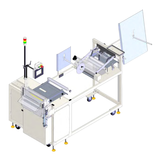
Page 16: Component Identification
Technical Manual & Parts Lists Component Identification Border Roller Holder Prefeed Drive Rollers Raise Roller Push Button Touch Screen 3200PB1 Mattress Border Guides Border Workstation Guillotine... -
Page 17: Touch Screen Operation
Light Tower Function The purpose of the 3200PB1 light tower is to indicate the current status of the machine at some distance away from the machine. This makes it easy to see machine status at a glance. Definitions for the different light states currently available on the 3200 are included below. -
Page 18: Machine Operation
Technical Manual & Parts Lists Machine Operation Turn on the power and select the desired language (if other than English) and wait until the touch screen displays the Ready – New Order screen. Initial Border Loading Procedure Press the Open Rollers button, the Prefeed Roller and the Main Roller lift up. Open the Material Guides wider than the expected border width to be loaded. -
Page 19: Setting Up The Machine To Make Borders
Technical Manual & Parts Lists Setting Up the Machine to Make Borders To setup the machine to make the desired borders go to the main Ready – New Order screen and press the large Edit New Order button. The new screen Edit Order displays all available options: the style, quantity of borders, and the type of fill material in the border (foam or fiber) can be set here. -
Page 20: Border Splicing Method
“Out of Border Material” message. Load the next border roll on the pin, and staple its leading edge to the trailing edge of the border currently in the machine. Also, to make the operation of the 3200PB1 machine more efficient, the border splicing on the Sewing Station must be performed correctly. -
Page 21: Motor Parameter Settings
Technical Manual & Parts Lists Motor Parameter Settings (3300A-PrePAR) Before Programming, Perform a Master Reset of Parameters (See Below) PARAMETER RANGE VALUE DESCRIPTION Mode of operation. MUST SET THIS PARAMETER FIRST! 0-999 0900 Maximum speed when "129" is 0, 1, or 2. Linear acceleration 0-50 Braking power at standstill... -
Page 22: Motor Parameter Settings (3300A Feedpar)
Technical Manual & Parts Lists Motor Parameter Settings (3300A FeedPAR) Before Programming, Perform a Master Reset of Parameters (See Below) PARAMETER RANGE VALUE DESCRIPTION Mode of operation. MUST SET THIS PARAMETER FIRST! 70-390 Positioning speed = 700 rpm 0-999 Maximum speed = 1200 rpm. Linear acceleration 0-50 Braking power at standstill... -
Page 23: Machine Maintenance
Technical Manual & Parts Lists Machine Maintenance Regularly scheduled maintenance of the 3200PB1 unit reduces possible problems and downtime. Proper care will also ensure a longer life and better performance of the machine. Perform the following procedures to properly maintain the machine. - Page 24 Technical Manual & Parts Lists...
-
Page 25: Assembly Drawings & Parts Lists
Company. In addition to any confidentiality and non-disclosure obligations that currently exist between you and Atlanta Attachment Company, your use of these materials serves as an acknowledgment of the confidential and proprietary nature of these materials and your duty not to make any unauthorized use or... - Page 26 Technical Manual & Parts Lists...
-
Page 27: 33200Pb1 Border Workstation, Measure & Cut
MAI N FRAME ASSEMBLY 32004000PB1 GUI LLOTI NE ASSEMBLY 32005000PA PREFEED ROLLER ASSY. 32007700P ROLL HOLDER ASSY 32009000PB1 CONTROL PANEL *AR 3200PB1-PD PNEUMATI C DI AGRAM *AR 3200PB1-WD1 DI AGRAM, WI RI NG 33004033A BRKT,GUARD,RI GHT SI DE 33004034B GUARD,TOP HALF,3300RA 33004035... - Page 28 Technical Manual & Parts Lists...
-
Page 29: 3200085 Small Roll Sewing Rod Assembly
Technical Manual & Parts Lists 3200085 Small Roll sewing Rod Assembly AAC Drawing Number 3200085 Rev0 QTY PART # DESCRIPTION 1961-251A HUB, UNWIND SHAFT 1961-253A HUB, UNWIND STAND 3200092 WELDMENT,MID ROD MOUNT 32005004 ROD,SS,3/4 X 24.0L 360-116 HUB, LOCKING 784-08-050 DISC,BB,SP,8"... - Page 30 Technical Manual & Parts Lists...
-
Page 31: 32003000Pa1 Main Frame Assembly
Technical Manual & Parts Lists 32003000PA1 Main Frame Assembly AAC Drawing Number 192131A Rev3 NO QTY PART # DESCRIPTION 4 1411-1063 THREADED ROD 1 28201 CROSS BLOCK 1 28203 STRAIGHT ROD 1 32003500P FRAME ASSY 2 32004035A NUT PLATE 1 32005011 FRONT DOOR 1 35005012 REAR DOOR... - Page 32 Technical Manual & Parts Lists...
-
Page 33: 32004000Pb1 Guillotine Assembly
Technical Manual & Parts Lists 32004000PB1 Guillotine Assembly AAC Drawing Number 192138A Rev2 NO QTY PART # DESCRIPTION NO QTY PART # DESCRIPTION 1 AAC7DP-1 AIR CYLINDER 3 SSFC98040 SCREW, FLAT ALLEN CAP 10-32 X5/8 1 AAFCT-7 CLEVIS, AIR CYL. 10 SSSC01048 SCREW, SOCKET CAP 1/4-20 X 3/4 1 BBAW-7... - Page 34 Technical Manual & Parts Lists...
-
Page 35: 32005000Pa Prefeed Roller Assembly
Technical Manual & Parts Lists 32005000PA Prefeed Roller Assembly AAC Drawing Number 192086A Rev6... - Page 36 Technical Manual & Parts Lists...
-
Page 37: 32007700P Roll Holder Assembly
Technical Manual & Parts Lists 32007700P Roll Holder Assembly AAC Drawing Number 192088A Rev1 QTY PART # DESCRIPTION 1961-253A Unwind Hub 784B-2436 Alu Plate WWL 3/8 Lock Washer 32007704 Roll Hold Frame 33008202 Rod, 3/4x21 WWSQ080B Washer SQ. Struct MM132-1496 End Cap SSHC25160 Hex Cap Screw3/8-16 x 2-1/2... - Page 38 Technical Manual & Parts Lists...
-
Page 39: 32009000Pb1 Control System
32 FF2264-371 TERMBLK, WAGO, END 12 SSPS90024 SCREW, PAN HD SLOTTED 8-32 X 3/8 1 FFRAV781BW MODULE, TVS 28 AR 12788-509A JUMPER, RESISTOR 29 AR 3200PB1-PD PNEUMATIC DIAGRAM 2 SSSC70024 SCREW, SOCKET CAP 4-40 X 3/8 31 AR 3200PLAB LABEL... - Page 40 Technical Manual & Parts Lists...
-
Page 41: 33005600 Prefeed Roller Assembly
Technical Manual & Parts Lists 33005600 Prefeed Roller Assembly AAC Drawing Number 192155C Rev7... - Page 42 Technical Manual & Parts Lists...
-
Page 43: 33005650A Bottom Puller Roller Assembly
Technical Manual & Parts Lists 33005650A Bottom Puller Roller Assembly AAC Drawing Number 192913B Rev3... - Page 44 Technical Manual & Parts Lists 3200PB1-PD Pneumatic Diagram 125389B...
- Page 45 Technical Manual & Parts Lists 3200PB1-WD Wiring Diagram 125390B...
- Page 46 Atlanta Attachment Company (AAC) Statement of Warranty Manufactured Products Atlanta Attachment Company warrants manufactured products to be free from defects in material and workmanship for a period of eight hundred (800) hours of operation or one hundred (100) days whichever comes first. Atlanta Attachment Company warrants all electrical components of the Serial Bus System to be free from defects in material or workmanship for a period of thirty six (36) months.
- Page 47 Declaración de Garantia Productos Manufacturados Atlanta Attachment Company garantiza que los productos de fabricación son libres de defectos de mate-rial y de mano de obra durante un periodo de ochocientos (800) horas de operación o cien (100) días cual llegue primero.
- Page 48 Atlanta Attachment Company 362 Industrial Park Drive Lawrenceville, GA 30046 770-963-7369 Printed in the USA www.atlatt.com...
Need help?
Do you have a question about the 3200PB1 and is the answer not in the manual?
Questions and answers