Moxa Technologies EDS-516A Series Installation Manual
Etherdevice
Hide thumbs
Also See for EDS-516A Series:
- User manual (99 pages) ,
- Hardware installation manual (16 pages) ,
- Manual (84 pages)
Table of Contents
Advertisement
Quick Links
Advertisement
Table of Contents

Related Manuals for Moxa Technologies EDS-516A Series


Summary of Contents for Moxa Technologies EDS-516A Series
- Page 1 MOXA EtherDevice™ Switch EDS-516A Series Hardware Installation Guide First Edition, November 2006 Moxa Networking Co., Ltd. Tel: +886-2-2910-1230 Fax: +886-2-2910-1231 www.moxa.com support@moxanet.com (Worldwide) support@usa.moxa.com (The Americas) P/N: 1802005160000...
-
Page 2: Package Checklist
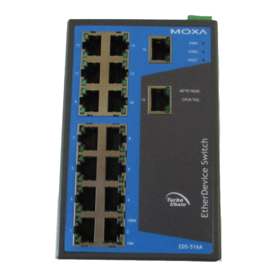
Package Checklist MOXA EtherDevice™ Switch is shipped with the following items. If any of these items are missing or damaged, please contact your customer service representative for assistance. 1 MOXA EtherDevice Switch EDS-516A Hardware Installation Guide CD-ROM with User’s Manual and Windows Utility Moxa Product Warranty Booklet RJ45 to DB9 Console port cable Protective caps for unused ports... - Page 3 Panel Views of EDS-516A Grounding screw Console port Heat dissipation orifices 6-pin terminal block for DI 1, DI 2, and PWR 2 6-pin terminal block for PWR1, Relay 1, and Relay 2 10/100BaseT(X), ports 1 to 16 PWR 1: LED for power input 1 PWR 2: LED for power input 2 Fault LED 10.
- Page 4 Panel Views of EDS-516A (SC/ST Type) NOTE: The appearance of EDS-516A-MM-ST is identical to EDS-516A-MM-SC. Grounding screw Console port Heat dissipation orifices 6-pin terminal block for DI 1, DI 2, and PWR 2 6-pin terminal block for PWR1, Relay 1, and Relay 2 10/100BaseT(X), ports 1 to 14 PWR 1: LED for power input 1 PWR 2: LED for power input 2...
-
Page 5: Mounting Dimensions (Unit = Mm)
Mounting Dimensions (unit = mm) 30.00 15.00 13.4 36.91 71.01 0.79 PWR1 PWR2 DlN-Rail FAULT 100M MASTER COUPLER 100M DlN-Rail Kit 100M Front View 127.52 Side View 18.2 13.9 13.9 DlN-Rail Kit 30.50 86.80 7.75 7.75 Rear View Wall Mounting Kit DIN-Rail Mounting The aluminum DIN-Rail attachment plate should already be fixed to the back panel of EDS-516A when you take it out of the box. -
Page 6: Wall Mounting (Optional)
Wall Mounting (Optional) For some applications, you will find it convenient to mount MOXA EDS-516A on the wall, as shown by the following illustrations: STEP 1—Remove the aluminum DIN-Rail attachment plate from the MOXA EDS-516A rear plate panel, and then attach the wall mount plates, as shown by the figure on the right. -
Page 7: Wiring The Relay Contact
ATTENTION This unit is a built-in type. When the unit is installed in another piece of equipment, the equipment enclosing the unit must comply with fire enclosure regulation IEC 60950/EN60950 (or similar regulation). ATTENTION Safety First! Be sure to disconnect the power cord before installing and/or wiring your MOXA EtherDevice Switch. -
Page 8: Wiring The Redundant Power Inputs
FAULT: The two sets of relay contacts of the 6-pin terminal block connector are used to detect user-configured events. The two wires attached to Relay1 Relay2 the Fault contacts form an open circuit when a user-configured event is triggered. If a user-configured event does not occur, the Fault circuit remains Relay1... -
Page 9: Communication Connections
Communication Connections All models of EDS-516A have one RJ45 console port (RS-232 interface), between 14 and 16 10/100BaseTX Ethernet ports. Some models also have 2 100BaseFX (SC/ST-type connector) fiber ports. In this section, we present two types of diagrams—Pinout Diagrams and Cable Wiring Diagrams—to convey information about the ports and the cables used to connect MOXA EDS-516A to other devices: Pinouts—The meaning of the “Pinouts”... - Page 10 RS-232 Connection MOXA EDS-516A has one RS-232 (10-pin RJ45) console port, located on the top panel. Use either an RJ45-to-DB9 or RJ45-to-DB25 cable (see the cable following wiring diagrams) to connect MOXA EDS-516A’s console port to your PC’s COM port. You may then use a console terminal program, such as MOXA PComm Terminal Emulator, to access MOXA EDS-516A’s console configuration utility.
-
Page 11: 10/100Baset(X) Ethernet Port Connection
10/100BaseT(X) Ethernet Port Connection The 10/100BaseT(X) ports located on MOXA EtherDevice Switch’s front panel are used to connect to Ethernet-enabled devices. Most users will choose to configure these ports for Auto MDI/MDI-X mode, in which case the port’s pinouts are adjusted automatically depending on the type of Ethernet cable used (straight-through or cross-over), and the type of device (NIC-type or HUB/Switch-type) connected to the port. -
Page 12: 100Basefx Ethernet Port Connection
100BaseFx Ethernet Port Connection The concept behind the SC/ST port and cable is quite straightforward. Suppose you are connecting devices I and II. As opposed to electrical signals, optical signals do not require a circuit in order to transmit data. Consequently, one of the optical lines is used to transmit data from device I to device II, and the other optical line is used transmit data from device II to device I, for full-duplex transmission. -
Page 13: Led Indicators
LED Indicators The front panel of MOXA EDS-516A contains several LED indicators. The function of each LED is described in the following table: Color State Description Power is being supplied to power input P1. AMBER PWR1 Power is not being supplied to power input P1. -
Page 14: Specifications
Specifications Technology Standards IEEE802.3, 802.3u, 802.3x, 802.1D, 802.1w, 802.1Q, 802.1p, 802.1X, 802.3ad, 802.3z Protocols IGMP V1/ V2/ V3 device, GMRP, GVRP, SNMP V1/V2c/V3, DHCP Server/Client, BootP, TFTP, SNTP, SMTP, RARP, RMON and EDS-SNMP OPC Server Pro (Optional) MIB-II, Ethernet-Like MIB, P-BRIDGE MIB, Q-BRIDGE MIB, Bridge MIB, RSTP MIB, RMON MIB Group 1,2,3,9 Interface... - Page 15 Power Input Voltage 24 VDC(12 to 45 VDC), redundant inputs Input Current (@24V) 0.31A: (EDS-516A) 0.39A: (EDS-516A-MM-SC/ST) Connection Two removable 6-pin terminal blocks Overload Current Protection Present Reverse Polarity Protection Present Mechanical Casing IP30 protection, metal case Dimensions 95 x 135 x 140 mm (W x H x D) Weight 1.586 kg Installation...
-
Page 16: Moxa Internet Services
MOXA Internet Services Customer satisfaction is our number one concern. To ensure that customers receive the full benefit of our products, Moxa has set up on-line support services to provide technical support, driver updates, product information, and user’s manual updates. E-mail for technical support: support@moxa.com (Worldwide)
Need help?
Do you have a question about the EDS-516A Series and is the answer not in the manual?
Questions and answers