
Related Manuals for Moxa Technologies EtherDevice EDS-516A-T


Summary of Contents for Moxa Technologies EtherDevice EDS-516A-T
- Page 1 EDS-516A Series Hardware Installation Guide Moxa EtherDevice™ Switch Sixth Edition, April 2014 2014 Moxa Inc. All rights reserved. P/N: 1802005160014...
-
Page 2: Package Checklist
Package Checklist Moxa EtherDevice™ Switch is shipped with the following items. If any of these items are missing or damaged, please contact your customer service representative for assistance. • 1 Moxa EtherDevice Switch EDS-516A • Hardware Installation Guide • CD-ROM with User’s Manual and Windows Utility •... - Page 3 Panel Views of EDS-516A 1. Grounding screw 2. Console port 3. Heat dissipation orifices 4. 6-pin terminal block for DI 1, DI 2, and PWR 2 5. 6-pin terminal block for PWR1 Relay 1, and Relay 2 6. 10/100BaseT(X), ports 1 to 16 7.
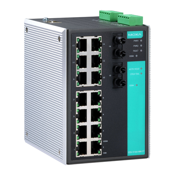
- Page 4 Panel Views of EDS-516A (SC/ST Type) NOTE: The appearance of EDS-516A-MM-ST is identical to EDS-516A-MM-SC. 1. Grounding screw 2. Console port 3. Heat dissipation orifices 4. 6-pin terminal block for DI 1, DI 2, and PWR 2 5. 6-pin terminal block for PWR1 Relay 1, and Relay 2 6.
-
Page 5: Mounting Dimensions
Mounting Dimensions Unit = mm (inch) - 5 -... -
Page 6: Din-Rail Mounting
DIN-Rail Mounting The aluminum DIN-Rail attachment plate should already be fixed to the back panel of EDS-516A when you take it out of the box. If you need to reattach the DIN-Rail attachment plate to EDS-516A, make sure the stiff metal spring is situated towards the top, as shown by the following figures. -
Page 7: Atex Information
STEP 3—Once the screws are fixed to the wall, insert the four screw heads through the wide parts of the keyhole-shaped apertures, and then slide the EDS-516A downwards, as indicated in the figure at the right. Tighten the four screws for more stability. - Page 8 ATTENTION Safety First! Be sure to disconnect the power cord before installing and/or wiring your Moxa EtherDevice Switch. Calculate the maximum possible current in each power wire and common wire. Observe all electrical codes dictating the maximum current allowable for each wire size. If the current goes above the maximum ratings, the wiring could overheat, causing serious damage to your equipment.
-
Page 9: Wiring The Relay Contact
Wiring the Relay Contact EDS-516A has two sets of relay outputs—relay 1 and relay 2. Each Relay Contact consists of the two contacts of the terminal block on EDS-516A’s top panel. You can refer to the next section for detailed instructions on how to connect the wires to the terminal block connector, and how to attach the terminal block connector to the terminal block receptor. -
Page 10: Wiring The Digital Inputs
Wiring the Digital Inputs EDS-516A has two sets of digital inputs, DI 1 and DI 2. Each DI consists of two contacts of the 6-pin terminal block connector on EDS’s top panel, which are used for EDS’s two DC inputs. The top and front views of one of the terminal block connectors are shown here. - Page 11 NOTE 1. The pin numbers for male DB9 and DB25 connectors, and hole numbers for female DB9 and DB25 connectors are labeled on the connector. However, the numbers are typically quite small, so you may need to use a magnifying glass to see the numbers clearly.
-
Page 12: 10/100Baset(X) Ethernet Port Connection
RJ45 (10-pin) to DB25 (F) Cable Wiring 10/100BaseT(X) Ethernet Port Connection The 10/100BaseT(X) ports located on Moxa EtherDevice Switch’s front panel are used to connect to Ethernet-enabled devices. Most users will choose to configure these ports for Auto MDI/MDI-X mode, in which case the port’s pinouts are adjusted automatically depending on the type of Ethernet cable used (straight-through or cross-over), and the type of device (NIC-type or HUB/Switch-type) connected to the port. - Page 13 RJ45 (8-pin) to RJ45 (8-pin) Cross-Over Cable Wiring 100BaseFx Ethernet Port Connection The concept behind the SC/ST port and cable is quite straightforward. Suppose you are connecting devices I and II. As opposed to electrical signals, optical signals do not require a circuit in order to transmit data. Consequently, one of the optical lines is used to transmit data from device I to device II, and the other optical line is used transmit data from device II to device I, for full-duplex transmission.
-
Page 14: Led Indicators
LED Indicators The front panel of Moxa EDS-516A contains several LED indicators. The function of each LED is described in the following table: Color State Description Power is being supplied to power input P1. PWR1 AMBER Power is not being supplied to power input P1. -
Page 15: Specifications
Specifications Technology Standards IEEE 802.3 for 10BaseT, IEEE 802.3u for 100BaseT(X) and 100Base FX, IEEE 802.3x for Flow Control, IEEE 802.1D for Spanning Tree Protocol, IEEE 802.1w for Rapid STP, IEEE 802.1Q for VLAN Tagging, IEEE 802.1p for Class of Service, IEEE 802.1X for Authentication, IEEE 802.3ad for Port Trunk with LACP Protocols... - Page 16 Regulatory Approvals Safety UL 508, UL 60950-1 CSA C22.2 No. 60950-1, EN 60950-1 Hazardous Location UL/cUL Class I, Division 2, Groups A, B, C, and D, ATEX Zone 2, Ex nA nC IIC T4 Gc FCC Part 15, CISPR (EN 55022) class A EN 61000-4-2 (ESD), Level 2 EN 61000-4-3 (RS), Level 3 EN 61000-4-4 (EFT), Level 2...
Need help?
Do you have a question about the EtherDevice EDS-516A-T and is the answer not in the manual?
Questions and answers