Table of Contents

Related Manuals for Digisol MUSTANG 4000 DG-FS4528


Summary of Contents for Digisol MUSTANG 4000 DG-FS4528
- Page 1 MUSTANG 4000 Managed Switch Series DG-FS4528/DG-FS4552 Layer 2 Fast Ethernet Managed Switch Installation Guide V1.0.2 2013-05-15 As our products undergo continuous development the specifications are subject to change without prior notice...
- Page 2 COPYRIGHT Copyright © 2013 by Smartlink Network Systems Limited. All rights reserved. No part of this publication may be reproduced, transmitted, transcribed, stored in a retrieval system, or translated into any language or computer language, in any form or by any means, electronic, mechanical, magnetic, optical, chemical, man- ual or otherwise, without the prior written permission of this company.
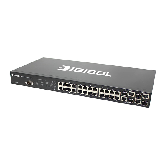
- Page 3 Installation Guide DG-FS4528/DG-FS4552 Fast Ethernet Switch Layer 2 Workgroup Switch with 24/48 10/100BASE-T (RJ-45) Ports, and 4 Combination Gigabit (RJ-45/SFP) Ports...
- Page 4 DG-FS4528 DG-FS4552 E102010-AP-R01 150000000234A...
- Page 5 About This Guide Purpose This guide details the hardware features of the switch, including the physical and performance-related characteristics, and how to install the switch. Audience The guide is intended for use by network administrators who are responsible for installing and setting up network equipment;...
-
Page 7: Table Of Contents
Contents Chapter 1: Introduction Overview Switch Architecture Network Management Options Description of Hardware 10/100BASE-T Ports SFP Slots Port and System Status LEDs Power Supply Sockets Features and Benefits Connectivity Expandability Performance Management Chapter 2: Network Planning Introduction to Switching Application Examples Collapsed Backbone Network Aggregation Plan Remote Connection with Fiber Cable... - Page 8 Contents Chapter 4: Making Network Connections Connecting Network Devices Twisted-Pair Devices Cabling Guidelines Connecting to PCs, Servers, Hubs and Switches Network Wiring Connections Fiber Optic SFP Devices Connectivity Rules 1000BASE-T Cable Requirements 1000 Mbps Gigabit Ethernet Collision Domain 100 Mbps Fast Ethernet Collision Domain 10 Mbps Ethernet Collision Domain Cable Labeling and Connection Records Appendix A: Troubleshooting...
- Page 9 Tables Table 1-1 DG-FS4552 Port Status LEDs Table 1-2 System Status LEDs Table 3-1. Serial Cable Wiring Table 4-1. Maximum 1000BASE-T Gigabit Ethernet Cable Length Table 4-2. Maximum 1000BASE-SX Gigabit Ethernet Cable Length Table 4-3. Maximum 1000BASE-LX Gigabit Ethernet Cable Length Table 4-4.
- Page 10 Figures Figure 1-1. DG-FS4552 Front and Rear Panels Figure 1-2. DG-FS4552 Port Status LEDs Figure 1-3. DG-FS4552 System Status LED Figure 1-4. DG-FS4552 Power Supply Sockets Figure 2-1. Collapsed Backbone Figure 2-2. Network Aggregation Plan Figure 2-3. Remote Connection with Fiber Cable Figure 2-4.
-
Page 11: Chapter 1: Introduction
Chapter 1: Introduction Overview The DG-FS4528/52 is an intelligent switch with 24/48 10/100BASE-T ports, and four Gigabit combination ports that are comprised of a RJ-45 port and an SFP transceiver slot. There is also an SNMP-based management agent embedded on the main board. -
Page 12: Switch Architecture
Introduction Switch Architecture The DG-FS4528/52 employs a wire-speed, non-blocking switching fabric. This permits simultaneous wire-speed transport of multiple packets at low latency on all ports. The DG-FS4528/52 also features full-duplex capability on all ports, which effectively doubles the bandwidth of each connection. he switch uses store-and-forward switching to ensure maximum data integrity. -
Page 13: Port And System Status Leds
DG-FS4552 Installation Guide Port and System Status LEDs The LEDs, which are located on the front panel for easy viewing, are shown below and described in the following table. Table 1-1 DG-FS4528 Port Status LEDs Condition Status RJ-45 Ports Link/ACT On/Blinking The port has a valid 10 or 100 Mbps link. -
Page 14: Power Supply Sockets
Introduction System Status led Mustang Mustang 4000 Series Switch 4000 Series Switch DG-FS4552 DG-FS4552 Figure 1-3. DG-FS4552 System Status LED Table 1-3 System Status LEDs Condition Status On Green Internal power is operating normally. (Power) On Amber Internal power supply has failed. Power off or failure. -
Page 15: Features And Benefits
DG-FS4552 Installation Guide Features and Benefits Connectivity • 48 10/100BASE-T ports plus 4 Gigabit combination ports (RJ-45/SFP). • Auto-negotiation enables each RJ-45 port to automatically select the optimum speed (10 or 100 Mbps), and the communication mode (half or full duplex) if this feature is supported by the attached device;... -
Page 16: Expandability
Introduction Expandability • 4 Small Form Factor Pluggable (SFP) transceiver slots (shared with 1000BASE-T ports) • Supports 1000BASE-SX and 1000BASE-LX, 1000BASE-LH and other SFP-compatible transceivers. Performance • Transparent bridging • Switching table with a total of 8K MAC address entries •... -
Page 17: Chapter 2: Network Planning
Chapter 2: Network Planning Introduction to Switching A network switch allows simultaneous transmission of multiple packets via non-crossbar switching. This means that it can partition a network more efficiently than bridges or routers. The switch has, therefore, been recognized as one of the most important building blocks for today’s networking technology. -
Page 18: Application Examples
Network Planning Application Examples The DG-FS4528/52 is not only designed to segment your network, but also to provide a wide range of options in setting up network connections. Some typical applications are described in the following pages. Collapsed Backbone The DG-FS4528/52 is an excellent choice for mixed Ethernet, Fast Ethernet, and Gigabit Ethernet installations where significant growth is expected in the near future. -
Page 19: Network Aggregation Plan
DG-FS4552 Installation Guide Network Aggregation Plan With 48 parallel bridging ports (i.e., 24 or 48 distinct collision domains), the switch can collapse a complex network down into a single efficient bridged node, increasing overall bandwidth and throughput. In the figure below, the 10/100BASE-TX ports on the switch are providing 100 Mbps connectivity through layer 2 switches. -
Page 20: Remote Connection With Fiber Cable
Network Planning Remote Connection with Fiber Cable Fiber optic technology allows for longer cabling than any other media type. A 1000BASE-SX (MMF) link can connect to a site up to 550 meters away, a 1000BASE-LX (SMF) link up to 5 km, and a 1000BASE-LH link up to 70 km. This allows the switch to serve as a collapsed backbone, providing direct connectivity for a widespread LAN. -
Page 21: Making Vlan Connections
DG-FS4552 Installation Guide Making VLAN Connections This switch supports VLANs which can be used to organize any group of network nodes into separate broadcast domains. VLANs confine broadcast traffic to the originating group, and can eliminate broadcast storms in large networks. This provides a more secure and cleaner network environment. -
Page 22: Application Notes
Network Planning Application Notes Full-duplex operation only applies to point-to-point access (such as when a switch is attached to a workstation, server or another switch). When the switch is connected to a hub, both devices must operate in half-duplex mode. Avoid using flow control on a port connected to a hub unless it is actually required to solve a problem. -
Page 23: Chapter 3: Installing The Switch
Chapter 3: Installing the Switch Selecting a Site Switch units can be mounted in a standard 19-inch equipment rack or on a flat surface. Be sure to follow the guidelines below when choosing a location. • The site should: • be at the center of all the devices you want to link and near a power outlet. be able to maintain its temperature within 0 to 45 °C (32 to 113 °F) and its humidity within 10% to 90%, non-condensing •... -
Page 24: Equipment Checklist
Installing the Switch RJ-45 Connector Figure 3-1. RJ-45 Connections Equipment Checklist After unpacking the switch, check the contents to be sure you have received all the components. Then, before beginning the installation, be sure you have all other necessary installation equipment. Package Contents •... -
Page 25: Mounting
DG-FS4552 Installation Guide Mounting This switch can be mounted in a standard 19-inch equipment rack or on a desktop or shelf. Mounting instructions for each type of site follow. Rack Mounting Before rack mounting the switch, pay particular attention to the following factors: •... -
Page 26: Desktop Or Shelf Mounting
Installing the Switch Mount the device in the rack, using four rack-mounting screws (not provided). Figure 3-3. Installing the Switch in a Rack If installing a single switch only, turn to "Connecting to a Power Source" at the end of this chapter. If installing multiple switches, mount them in the rack, one below the other, in any order. -
Page 27: Installing An Optional Sfp Transceiver
DG-FS4552 Installation Guide Installing an Optional SFP Transceiver Figure 3-5. Inserting an SFP Transceiver into a Slot The switch supports 1000BASE-SX and 1000BASE-LX, 1000BASE-LH and other SFP-compatible transceivers. To install an SFP transceiver, do the following: Consider network and cabling requirements to select an appropriate SFP transceiver type. -
Page 28: Connecting To A Power Source
Installing the Switch Connecting to a Power Source To connect a device to a power source: Insert the power cable plug directly into the socket located at the back of the device. Figure 3-6. Power Sockets Plug the other end of the cable into a grounded, 3-pin socket. Note: For International use, you may need to change the AC line cord. -
Page 29: Connecting To The Console Port
DG-FS4552 Installation Guide Connecting to the Console Port The DB-9 serial port on the switch’s front panel is used to connect to the switch for out-of-band console configuration. The on-board configuration program can be accessed from a terminal or a PC running a terminal emulation program. The pin assignments used to connect to the serial port are described in the following figure and table. - Page 30 Installing the Switch...
-
Page 31: Chapter 4: Making Network Connections
Chapter 4: Making Network Connections Connecting Network Devices The DG-FS4528/52 is designed to interconnect multiple segments (or collision domains). It can be connected to network cards in PCs and servers, as well as to hubs, switches or routers. It may also be connected to devices using optional SFP tranceivers. -
Page 32: Network Wiring Connections
Making Network Connections If the device is a PC card and the switch is in the wiring closet, attach the other end of the cable segment to a modular wall outlet that is connected to the wiring closet. (See "Network Wiring Connections" on page 4-2.) Otherwise, attach the other end to an available port on the switch. -
Page 33: Fiber Optic Sfp Devices
DG-FS4552 Installation Guide Fiber Optic SFP Devices An optional Gigabit SFP transceiver (1000BASE-SX, 1000BASE-LX, or 1000BASE-LH) can be used for a backbone connection between switches, or for connecting to a high-speed server. Each multimode fiber optic port requires 50/125 or 62.5/125 micron multimode fiber optic cabling with an LC connector at both ends. -
Page 34: Connectivity Rules
Making Network Connections Figure 4-3. Making Fiber Port Connections As a connection is made, check the Link LED on the switch corresponding to the port to be sure that the connection is valid. The 1000BASE-SX, 1000BASE-LX and 1000BASE-LH fiber optic ports operate at 1 Gbps full duplex, with auto-negotiation of flow control. -
Page 35: 1000 Mbps Gigabit Ethernet Collision Domain
DG-FS4552 Installation Guide 1000 Mbps Gigabit Ethernet Collision Domain Table 4-1. Maximum 1000BASE-T Gigabit Ethernet Cable Length Cable Type Maximum Cable Length Connector Category 5, 5e, 6 100-ohm UTP or STP 100 m (328 ft) RJ-45 Table 4-2. Maximum 1000BASE-SX Gigabit Ethernet Cable Length Fiber Size Fiber Bandwidth Maximum Cable Length... -
Page 36: Cable Labeling And Connection Records
Making Network Connections Cable Labeling and Connection Records When planning a network installation, it is essential to label the opposing ends of cables and to record where each cable is connected. Doing so will enable you to easily locate inter-connected devices, isolate faults and change your topology without need for unnecessary time consumption. -
Page 37: Appendix A: Troubleshooting
Appendix A: Troubleshooting Diagnosing Switch Indicators Table A-1. Troubleshooting Chart Symptom Action Power LED is Off • Power supply is disconnected. • Check connections between the switch, the power cord, and the wall outlet. • Contact your dealer for assistance. Power LED is Amber •... -
Page 38: In-Band Access
Troubleshooting In-Band Access You can access the management agent in the switch from anywhere within the attached network using Telnet, a Web browser, or other network management software tools. However, you must first configure the switch with a valid IP address, subnet mask, and default gateway. -
Page 39: Appendix B: Cables
Appendix B: Cables Twisted-Pair Cable and Pin Assignments For 10/100BASE-TX connections, a twisted-pair cable must have two pairs of wires. For 1000BASE-T connections the twisted-pair cable must have four pairs of wires. Each wire pair is identified by two different colors. For example, one wire might be green and the other, green with white stripes. -
Page 40: Straight-Through Wiring
Cables Table B-1. 10/100BASE-TX MDI and MDI-X Port Pinouts MDI Signal Name MDI-X Signal Name Transmit Data plus (TD+) Receive Data plus (RD+) Transmit Data minus (TD-) Receive Data minus (RD-) Receive Data plus (RD+) Transmit Data plus (TD+) Receive Data minus (RD-) Transmit Data minus (TD-) Not used Not used... -
Page 41: 1000Base-T Pin Assignments
DG-FS4552 Installation Guide 10/100BASE-TX Crossover Cable White/Orange Stripe Orange White/Green Stripe End A End B Blue White/Blue Stripe Green White/Brown Stripe Brown Figure B-3. Crossover Wiring 1000BASE-T Pin Assignments All 1000BASE-T ports support automatic MDI/MDI-X operation, so you can use straight-through cables for all network connections to PCs or servers, or to other switches or hubs. - Page 42 Cables Cable Testing for Existing Category 5 Cable Installed Category 5 cabling must pass tests for Attenuation, Near-End Crosstalk (NEXT), and Far-End Crosstalk (FEXT). This cable testing information is specified in the ANSI/TIA/EIA-TSB-67 standard. Additionally, cables must also pass test parameters for Return Loss and Equal-Level Far-End Crosstalk (ELFEXT).
-
Page 43: Appendix C: Specifications
Appendix C: Specifications Physical Characteristics Physical Ports DG-FS4528 24 100Base-TX ports 4 Combo Gigabit (RJ-45/SFP) ports 1 RS-232 DB-9 console port DG-FS4552 48 100Base-TX ports 4 Combo Gigabit (RJ-45/SFP) ports 1 RS-232 DB-9 console por Buffer Architecture 4 Mbits Aggregate Bandwidth DG-FS4528: 12.8Gbps DG-FS4552: 17.6 Gbps Switching Database... -
Page 44: Switch Features
Specifications Temperature Operating: 0 to 45 °C (32 to 113 °F) Storage: -40 to 70 °C (-40 to 158 °F) Humidity Operating: 10% to 90% (non-condensing) Power Supply DG-FS4528/52: Internal, auto-ranging transformer: 100 to 240 V, 50-60 Hz, 1 A Power Consumption 30 Watts maximum Maximum Current... -
Page 45: Standards
DG-FS4552 Installation Guide Standards IEEE 802.3 Ethernet IEEE 802.3u Fast Ethernet IEEE 802.3z and 802.3ab Gigabit Ethernet IEEE 802.1D (Bridging) IEEE 802.3x full-duplex flow control IEEE 802.1Q (Virtual LAN) ISO/IEC 8802-3... - Page 46 Specifications...
-
Page 47: Glossary
Glossary 10BASE-T IEEE 802.3 specification for 10 Mbps Ethernet over two pairs of Category 3, 4, or 5 UTP cable. 100BASE-TX IEEE 802.3u specification for 100 Mbps Ethernet over two pairs of Category 5 UTP cable. 1000BASE-LH Specification for long-haul Gigabit Ethernet over two strands of 9/125 micron core fiber cable. - Page 48 Glossary CSMA/CD CSMA/CD (Carrier Sense Multiple Access/Collision Detect) is the communication method employed by Ethernet, Fast Ethernet, or Gigabit Ethernet. End Station A workstation, server, or other device that does not forward traffic. Ethernet A network communication system developed and standardized by DEC, Intel, and Xerox, using baseband transmission, CSMA/CD access, logical bus topology, and coaxial cable.
- Page 49 DG-FS4552 Installation Guide IEEE 802.3x Defines Ethernet frame start/stop requests and timers used for flow control on full-duplex links. IEEE 802.3z Defines CSMA/CD access method and physical layer specifications for 1000BASE Gigabit Ethernet. LAN Segment Separate LAN or collision domain. Light emitting diode used for monitoring a device or network condition.
- Page 50 Glossary Transmission Control Protocol/Internet Protocol (TCP/IP) Protocol suite that includes TCP as the primary transport protocol, and IP as the network layer protocol. Unshielded twisted-pair cable. Virtual LAN (VLAN) A Virtual LAN is a collection of network nodes that share the same collision domain regardless of their physical location or connection point in the network.
-
Page 51: Index
Index equipment checklist 3-2 Numerics Ethernet connectivity rules 4-5 10 Mbps connectivity rules 4-5 100 Mbps connectivity rules 4-5 1000BASE-T Fast Ethernet connectivity rules 4-5 pin assignments B-3 features C-2 ports 1-2 management 1-5 100BASE-TX switch 1-4 pin assignments B-1 fiber cables 4-3 ports 1-2 full duplex connectivity 2-1... - Page 52 Index on a desktop or shelf 3-4 pinouts B-3 multimode fiber optic cables 4-3 rubber foot pads, attaching 3-4 network screws for rack mounting 3-2 connections 4-1 site selelction 3-1 examples 2-2 SNMP agent 1-2 specifications environmental C-2 physical C-1 out-of-band management 1-2 power C-2 status LEDs 1-3...
Need help?
Do you have a question about the MUSTANG 4000 DG-FS4528 and is the answer not in the manual?
Questions and answers