
Related Manuals for Digisol DG-CS4616F


Summary of Contents for Digisol DG-CS4616F
- Page 1 DG-CS4616F GIGA LAYER 3 SWITCH Installation Guide V1.0 2018-01-30 As our products undergo continuous development the specifications are subject to change without prior notice...
-
Page 2: Table Of Contents
DG-CS4616F Installation Guide Content Chapter 1 Introduction..............1 1.1 Product Brief....................1 1.1.1 Introduction......................1 1.2 Physical Specifications................1 1.3 Description of Hardware................2 1.3.1 Front Panel......................2 1.3.2 Back Panel......................2 1.3.3 Status LEDs......................2 1.3.4 Front Panel Port Description................3 Chapter 2 Hardware Installation............ -
Page 3: Chapter 1 Introduction
DG-CS4616F switch can serve ideally as distribution layer switch for the 10Gb input device of campus networks, enterprise networks and IP metropolitan networks. DG-CS4616F is also used in the Internet bar as the full 10Gb convergence device. 1.2 Physical Specifications Management Port ... -
Page 4: Description Of Hardware
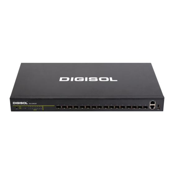
Fig 1- 2 Front Panel of DG-CS4616F 1.3.2 Back Panel The back panel of DG-CS4616F is shown below, there is a fan, 1 220V AC power socket, 1 -48V DC power socket and 1 ground screw hole. Fig 1- 3 Back Panel of DG-CS4616F 1.3.3 Status LEDs... -
Page 5: Front Panel Port Description
DG-CS4616F Installation Guide Fig 1- 4 DG-CS4616F LED LED diagram Table 1-1 DG-CS4616F port indications description Panel Symbol Status Description On (Green) ports are in successful link state ports are in successful link state and Port 1-16(Link/Act) Flash(Green) receive/send data ports are not in link 1.3.3.2 System Status Indication Description... - Page 6 DG-CS4616F Installation Guide Table 1- 3 DG-CS4616F switch port description Interface mode Spec RJ-45 port 10/100/1000Mbps auto negotiation MDI/MDI-X cable mode auto negotiation 5 kinds of UTP: 100 m SFP-SX-L transceiver 1000Base-SX SFP (850nm, MMF, 550m) SFP-LX-L transceiver ...
-
Page 7: Chapter 2 Hardware Installation
2.1.1.1 Dust and Particles Dust is harmful to the safe operation of DG-CS4616F. Dust can lead to electrostatic adherence, especially likely under low relative humidity, causing poor contact of metal connectors or contacts. Electrostatic adherence will result in not only reduced product lifespan, but also increased chance of communication failures. - Page 8 DG-CS4616F Installation Guide Table 2- 1Environmental Requirements: Dust In addition, salt, acid and sulfide in the air are also harmful to the switch. Such harmful gases will aggravate metal corrosion and the aging of some parts. The site should avoid harmful gases, such as SO...
- Page 9 DG-CS4616F Installation Guide Caution! A sample of ambient temperature and humidity should be taken at 1.5m above the floor and 0.4m in front of the switch rack, with no protective panel covering the front and rear of the rack. Short term working conditions refer to a maximum of 48 hours of continued operation and an annual cumulative total of less than 15 days.
-
Page 10: Installation Notice
Caution! If a standard 19’’ rack is not available, the DG-CS4616F can be placed on a clean level desktop, leave a clearance of 100mm around the switch for ventilation, and do not place anything on top of the switch. -
Page 11: Security Warnings
DG-CS4616F Installation Guide users should ensure the switch is well grounded. Users should maintain the switch regularly to extend the lifespan of the switch. 2.1.3 Security Warnings When using SFP/SFP+ transceiver, do not stare directly at the fiber bore when the ... -
Page 12: Installation Preparation
Users should prepare the required tools and utilities by themselves. 2.3 Installation Guide 2.3.1 Installing the Switch Please mount DG-CS4616F switch as below: 1. Attach the 2 brackets on the DG-CS4616F with screws provided in the accessory kit. Fig 2- 1 Fasten the Brackets to the Switch Chapter 2-6... -
Page 13: Connecting Console
DG-CS4616F Installation Guide 2. Put the bracket-mounted switch smoothly into a standard 19’’ rack. Fasten the DG-CS4616F to the rack with the screws provided. Leave enough space around the switch for good air circulation. Fig 2- 2 Fasten the Switch to the Rack Caution! The brackets are used to fix the switch on the rack. -
Page 14: Sfp/Sfp+ Transceiver Installation
Power on the switch and the character terminal. Configure the switch through the character terminal. 2.3.3 SFP/SFP+ Transceiver Installation DG-CS4616F has multiple 10Gb interfaces and provides multiple 1000Mb SFP or 10Gb SFP+ transceiver slots. The procedure for installing the SFP/SFP+ transceiver is shown below: Step 1: Put on a ESD wrist strap (or antistatic gloves) Step 2: Insert the SFP/SFP+ transceiver to the guide rail inside the fiber interface line card. -
Page 15: Power Supply Connection
Do not stare at the fiber bore when the switch is in operation. That may hurt your eyes. 2.3.5 Power Supply Connection DG-CS4616F uses 220V AC power. Please read the power input specification for the detailed information. Power supply connection procedure is described as below:... -
Page 16: Ground Cable Connection
2. Check the power status indicator in the front panel of the switch. The corresponding power indicator should light. DG-CS4616F is self-adjustable for the input voltage. As soon as the input voltage is in the range printed on the switch surface, the switch can operate correctly. - Page 17 DG-CS4616F Installation Guide 3. Installation steps: Step 1: Ensure the power switch is set to the off position. Step 2: Use the screwdriver to turn the screws on the earth ground screw point. Step 3: Strip one end of the ground wire to the ground hole of system.
Need help?
Do you have a question about the DG-CS4616F and is the answer not in the manual?
Questions and answers