Table of Contents
Advertisement
Quick Links
Quick Installation Guide
Moxa Americas:
Toll-free: 1-888-669-2872
Tel:
1-714-528-6777
Fax:
1-714-528-6778
Moxa Europe:
Tel:
+49-89-3 70 03 99-0
Fax:
+49-89-3 70 03 99-99
Moxa India:
Tel:
+91-80-4172-9088
Fax:
+91-80-4132-1045
PT-508 Series
Moxa PowerTrans Switch
Edition 6.0, February 2017
Technical Support Contact Information
www.moxa.com/support
2017 Moxa Inc. All rights reserved.
Moxa China (Shanghai office):
Toll-free: 800-820-5036
Tel:
+86-21-5258-9955
Fax:
+86-21-5258-5505
Moxa Asia-Pacific:
Tel:
+886-2-8919-1230
Fax:
+886-2-8919-1231
P/N: 1802005080014
*1802005080014*
Advertisement
Table of Contents

Related Manuals for Moxa Technologies PowerTrans PT-508-MM-ST-48


Summary of Contents for Moxa Technologies PowerTrans PT-508-MM-ST-48
- Page 1 PT-508 Series Quick Installation Guide Moxa PowerTrans Switch Edition 6.0, February 2017 Technical Support Contact Information www.moxa.com/support Moxa Americas: Moxa China (Shanghai office): Toll-free: 1-888-669-2872 Toll-free: 800-820-5036 Tel: 1-714-528-6777 Tel: +86-21-5258-9955 Fax: 1-714-528-6778 Fax: +86-21-5258-5505 Moxa Europe: Moxa Asia-Pacific: Tel: +49-89-3 70 03 99-0 Tel: +886-2-8919-1230...
-
Page 2: Package Checklist
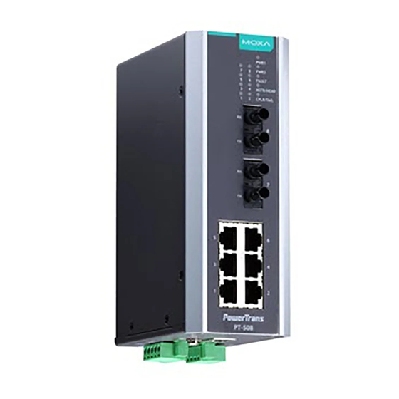
Package Checklist Moxa’s PT-508 PowerTrans switch is shipped with the following items. If any of these items is missing or damaged, please contact your customer service representative for assistance. • PT-508 PowerTrans switch • RJ45 to DB9 console port cable •... - Page 3 Panel Layout of the PT-508 1. Power input PWR1/PWR2(DC model only) LED 2. LEDs for ports 1 to 8 3. Fault LED 4. MSTR/HEAD: LED indicator 5. CPLR/TAIL: LED indicator 6. 100BaseFX ports (SC/ST/LC/MTRJ) 7. 10/100BaseT(X) ports 8. Model Name 9.
-
Page 4: Mounting Dimensions (Unit = Mm)
Mounting Dimensions (unit = mm) - 4 -... -
Page 5: Din-Rail Mounting
DIN-Rail Mounting The aluminum DIN-Rail attachment plate should already be fixed to the back panel of the PT-508 when you take it out of the box. If you need to reattach the DIN-Rail attachment plate to the PT-508, make sure the stiff metal spring is situated towards the top as shown in the figures below. -
Page 6: Wall Mounting (Optional)
Wall Mounting (optional) For added convenience, the PT-508 can be wall mounted as illustrated below. STEP 1: Remove the aluminum DIN-Rail attachment plate from the PT-508’s rear panel, and then attach the wall mount plates with 6 M3 screws, as shown on the right. - Page 7 Please read and follow these important guidelines: • Use separate paths to route wiring for power and devices. If power wiring and device wiring paths must cross, make sure the wires are perpendicular at the intersection point. NOTE: Do not run signal or communications wiring and power wiring in the same wire conduit.
-
Page 8: Wiring The Relay Contact
Wiring the Relay Contact The PT-508 has one set of relay output—relay 1. The relay contact consists of two contacts of the terminal block on the PT-508’s bottom panel. Refer to the next section for detailed instructions on how to connect the wires to the terminal block connector, and how to attach the terminal block connector to the terminal block receptor. -
Page 9: Wiring The Digital Inputs
Wiring the Power Input (110/220 VDC/VAC model) The PT-508 unit (110/220 VDC/VAC model) has one set of power input— Pin 1(Neutral) and Pin5(Line). To insert the terminal block connector prongs into the terminal block receptor on this PT-508 unit properly. Please take the following steps to wire the power input. -
Page 10: Pin Assignments
Pin Assignments PT-508 models have six 10/100BaseT(X) Ethernet ports, and two 100BaseFX (SC/ST/LC/MTRJ-type connector) fiber ports. 10/100BaseT(X) Ethernet Port Connection The 10/100BaseT(X) ports located on PT’s front panel are used to connect to Ethernet-enabled devices. Next, we show pinouts for both MDI (NIC-type) ports and MDI-X (HUB/Switch-type) ports, and also show cable wiring diagrams for straight-through and cross-over Ethernet cables. -
Page 11: 100Basefx Ethernet Port Connection
100BaseFX Ethernet Port Connection When connecting device 1 to device 2, remember to connect the Tx (transmit) port of device 1 to the Rx (receive) port of device 2, and the Rx (receive) port of device 1 to the Tx (transmit) port of device 2. If you make your own cable, we suggest labeling the two sides of the same line with the same letter (A-to-A and B-to-B, as shown below, or A1-to-A2 and B1-to-B2). -
Page 12: Front Panel Leds
Front Panel LEDs The PT-508’s front panel has five LED indicators, refer to the following table for details. Color State Description Power is being supplied to power input PWR1. PWR1 AMBER Power is not being supplied to power input PWR1. Power is being supplied to power input PWR2 PWR2. -
Page 13: Auto Mdi/Mdi-X Connection
Auto MDI/MDI-X Connection The Auto MDI/MDI-X function allows users to connect the PT-508’s 10/100BaseTX ports to any type of Ethernet device using either a straight-through cable or cross-over cable. Fiber Ports The fiber ports are factory-built as either multi-mode/single-mode SC/ST/LC connectors or multi-mode MTRJ connectors. You should use fiber cables that have SC/ST/LC/MTRJ connectors at both ends. - Page 14 Digital Input One input with the same ground, but electrically isolated from the electronics • For state “1”: +13 to +30V • For state “0”: -30 to +3V • Max. input current: 8 mA Optical Fiber: Single mode, Multi-mode Single mode 80 km Wavelength 1300 nm...
Need help?
Do you have a question about the PowerTrans PT-508-MM-ST-48 and is the answer not in the manual?
Questions and answers