EUCHNER MGB-L0 AR Series Operating Instructions Manual
Safety systems
Hide thumbs
Also See for MGB-L0 AR Series:
- Operating instructions manual (48 pages) ,
- Operating instructions manual (40 pages)

Related Manuals for EUCHNER MGB-L0 AR Series


Summary of Contents for EUCHNER MGB-L0 AR Series
- Page 1 Operating Instructions Safety Systems MGB-L0…-AR.-… MGB-L0…-AP.-… from V3.0.0...
-
Page 2: Table Of Contents
Operating Instructions Safety Systems MGB-L0…-AR.-… and MGB-L0…-AP.-… Contents About this document ..................... 4 1.1. Scope ............................4 1.1.1. Notes on older product versions ..................4 1.2. Target group ..........................4 1.3. Key to symbols ..........................4 1.4. Supplementary documents ......................5 Correct use ......................6 2.1. - Page 3 Operating Instructions Safety Systems MGB-L0…-AR.-… and MGB-L0…-AP.-… 11.10. Operation in an AR switch chain .....................28 11.11. Information on operation in an AR switch chain ................29 11.11.1. System times .......................29 11.11.2. Wiring an AR switch chain ....................29 11.11.3. Number of devices in switch chains ................29 11.11.4.
-
Page 4: About This Document
This section applies on operation as MGB-AP This section applies on operation as MGB-AR In this section attention must be paid to the DIP switch settings Printed document Document is available for download at www.euchner.com Document on CD Safety precautions Danger of death or severe injuries... -
Page 5: Supplementary Documents
Important! Always read all documents to gain a complete overview of safe installation, setup and use of the device. The documents can be downloaded from www.euchner.com. For this purpose enter the doc. no. in the search box. 2112657-13-05/18 (translation of the original operating instructions) -
Page 6: Correct Use
The safety system MGB can be combined only with the intended modules in the MGB system family. On the modification of system components, EUCHNER provides no warranty for function. Interlocking modules with the configuration MGB-AR can be integrated into an AR switch chain. -
Page 7: Main Differences Between Mgb-Ap And Mgb-Ar
Operating Instructions Safety Systems MGB-L0…-AR.-… and MGB-L0…-AP.-… Table 1: Possible combinations for MGB components Handle module Evaluation unit MGB-H-... from V2.0.0 MGB…AR/AP from V3.0.0 Key to symbols Combination possible 2.1. Main differences between MGB-AP and MGB-AR System family Symbol Optimized for operation in safe control systems. MGB-AP If series connection is not necessary, the number of terminals required can be reduced using this system family. -
Page 8: Description Of The Safety Function
Operating Instructions Safety Systems MGB-L0…-AR.-… and MGB-L0…-AP.-… 3. Description of the safety function Devices from this series feature the following safety functions: Monitoring of the guard position (interlocking device according to EN ISO 14119) Ì Safety function: the safety outputs are switched off when the guard is open (see chapter 6. Function on page 10). Ì... -
Page 9: Exclusion Of Liability And Warranty
Prior to use, read the operating instructions and keep these in a safe place. Ensure the operating instructions are always available during mounting, setup and servicing. EUCHNER cannot provide any warranty in relation to the readability of the CD for the storage period required. For this reason you should archive a printed copy of the operating instructions. -
Page 10: Function
Operating Instructions Safety Systems MGB-L0…-AR.-… and MGB-L0…-AP.-… 6. Function Together with a handle module, the interlocking module makes it possible to monitor the position of moving guards. The combination also serves as a mechanical door stop at the same time. The following switch-on condition applies to the safety outputs FO1A and FO1B (also see chapters 14.2. -
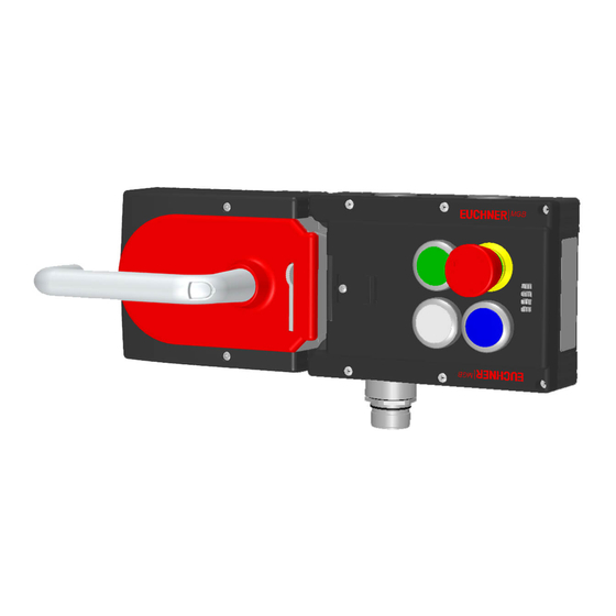
Page 11: System Overview
Operating Instructions Safety Systems MGB-L0…-AR.-… and MGB-L0…-AP.-… 7. System overview 7.1. Interlocking module MGB-L0-… Key: Cover for auxiliary release LED indicator DIP switches Terminals X2 -X5 Depending on version: Cable entry M20x1.5 or plug connector Internal reset Auxiliary marking for maximum permitted mounting distance Notice: Depending on the version, additional controls and indicators may be integrated into the cover and a mounting plate can be included. -
Page 12: Dimension Drawing
Operating Instructions Safety Systems MGB-L0…-AR.-… and MGB-L0…-AP.-… (translation of the original operating instructions) 2112657-13-05/18... -
Page 13: Lockout Mechanism
Operating Instructions Safety Systems MGB-L0…-AR.-… and MGB-L0…-AP.-… 7.5. Lockout mechanism If the lockout mechanism is pivoted out/extended, the bolt tongue cannot be extended. The lockout mechanism can be secured with padlocks (see Figure 5). To pivot out, press the grooved part (possible only with bolt tongue retracted). ¨... -
Page 14: Escape Release (Optional)
Align escape release axis at right angles to the handle module. See Figure 4 and Figure 7. 7.6.1. Preparing escape release (also see Figure 6: Preparing escape release on page 15) Profile width Length required for actuation Which EUCHNER parts are required? Necessary work steps axis Without plates With mounting... - Page 15 Operating Instructions Safety Systems MGB-L0…-AR.-… and MGB-L0…-AP.-… Example with mounting plates: Actuation axis Protective sleeve Mounting plates 1 Fit door handle. 2 Insert actuation axis. The locking ring A must be in contact with the escape release B. 3 Tighten setscrew to 2 Nm. 4 Fit protective sleeve.
-
Page 16: Installation
Surface mounting Tip! Ì You will find an animation on the mounting process at www.euchner.com. Ì The color and labeling of pushbuttons and indicators can be modified. For mounting steps , see Figure 7 and Figure 8 to Figure 13. -
Page 17: Mounting Lens
Operating Instructions Safety Systems MGB-L0…-AR.-… and MGB-L0…-AP.-… 8.1. Mounting lens Installation 90° Click! Removal Lens 2112657-13-05/18 (translation of the original operating instructions) - Page 18 Operating Instructions Safety Systems MGB-L0…-AR.-… and MGB-L0…-AP.-… 2x M6 1 Nm (6x) Cutout for escape release Tightening torque 6 Nm 4x M6 0,5 Nm Recommended fixing material: For mounting on the mounting plate: DIN 912-M6X25-8.8 ZN CYLINDER HEAD SCREW Figure 7: Installation example for door hinged on the right (general view) (translation of the original operating instructions) 2112657-13-05/18...
-
Page 19: Changing Actuating Direction (Here: From Right To Left)
Operating Instructions Safety Systems MGB-L0…-AR.-… and MGB-L0…-AP.-… 9. Changing actuating direction (here: from right to left) Important! It is possible to make this change only when the bolt tongue is not extended and an escape release is not yet mounted. As supplied, the handle module is set either for doors hinged on the right or for doors hinged on the left. -
Page 20: Protection Against Environmental Effects
Operating Instructions Safety Systems MGB-L0…-AR.-… and MGB-L0…-AP.-… 3 mm CLOSED 9 Remove cover and undo hexagon socket screw. OPEN AT Reposition the door handle by 90° in clockwise direction and fasten it again. A Tighten hexagon socket screw to 3 Nm A... -
Page 21: Electrical Connection
Operating Instructions Safety Systems MGB-L0…-AR.-… and MGB-L0…-AP.-… 11. Electrical connection WARNING If there is a mistake, loss of the safety function due to incorrect connection. Ì To ensure safety, both safety outputs (FO1A and FO1B) must always be evaluated. Ì The monitoring outputs must not be used as safety outputs. -
Page 22: Notes About
The mounting of conduits directly on the MGB is not allowed. Cables are allowed to be connected only via suitable cable glands. For this purpose use EUCHNER cable gland of type EKPM20/06U. Equivalent cable glands can be used if they are UL-listed (QCRV) and are suitable for the related cable diameter (22 AWG –... -
Page 23: Requirements For Connection Cables
Ì On the usage of other connection components, the requirements in the following table apply. EUCHNER provides no warranty for safe function in case of failure to comply with these require- ments. Observe the following requirements with respect to the connection cables:... -
Page 24: Changing Device Configuration (Using Dip Switches)
MGB-L0…-AR.-… and MGB-L0…-AP.-… 11.6. Changing device configuration (using DIP switches) Tip! You will find an animation on device configuration at www.euchner.com. DIP switches The devices can be configured using the DIP switches. The following settings are possible: Ì Changing system family (AR/AP switching) -
Page 25: Notes On Operation With Control Systems
Always connect inputs FI1A and FI1B directly to a power supply unit or to outputs FO1A and FO1B of another EUCHNER AR device (series connection). Pulsed signals must not be present at inputs FI1A and FI1B. The test pulses are also present when the safety outputs are switched off (only on FO1A). Depending on the inertia of the downstream device (control system, relay, etc.), this can lead to short switching processes. -
Page 26: Terminal Assignment And Contact Description
Operating Instructions Safety Systems MGB-L0…-AR.-… and MGB-L0…-AP.-… 11.8. Terminal assignment and contact description LEDs State Power Figure 15: Connections and LEDs Terminal Designation Description X3.1 to X3.3 See the enclosed data sheet X3.4 Power supply for monitoring outputs and cover assembly, DC 24 V, must be permanently present. X3.5 Ground, DC 0 V (connected internally to X5.5). -
Page 27: Operation As Separate Device
Operating Instructions Safety Systems MGB-L0…-AR.-… and MGB-L0…-AP.-… 11.9. Operation as separate device +24 V DC FI1A FI1B X3:4 X5:6 X4:1 X4:2 X4:6 X2:3 X2:4 X3:1 X3:3 Safety Inputs Safety Monitoring Outputs Outputs X5:5 X3:5 X4:4 X4:5 X5:1 X5:2 X5:4 X2:1 X2:2 X2:6 X2:7... -
Page 28: Operation In An Ar Switch Chain
Operating Instructions Safety Systems MGB-L0…-AR.-… and MGB-L0…-AP.-… 11.10. Operation in an AR switch chain +24 V DC FI1A FI1B X3:4 X5:6 X4:1 X4:2 X4:6 X2:3 X2:4 X3:1 X3:3 Safety Inputs Safety Monitoring Outputs Outputs X5:5 X3:5 X4:4 X4:5 X5:1 X5:2 X5:4 X2:1 X2:2... -
Page 29: Information On Operation In An Ar Switch Chain
Operating Instructions Safety Systems MGB-L0…-AR.-… and MGB-L0…-AP.-… 11.11. Information on operation in an AR switch chain 11.11.1. System times The interlocking module has longer reaction times than a CES-AR switch (see chapters 13. Technical data on page 32 and 13.1. Typical system times on page 33). 11.11.2. -
Page 30: Commissioning
Operating Instructions Safety Systems MGB-L0…-AR.-… and MGB-L0…-AP.-… 12. Commissioning 12.1. Teach-in operation (only for MGB unicode) The handle module must be assigned to the interlocking module using a teach-in function before the system comprising interlocking module and handle module forms a functional unit. During a teach-in operation the safety outputs are switched off. -
Page 31: Electrical Function Test
Operating Instructions Safety Systems MGB-L0…-AR.-… and MGB-L0…-AP.-… 12.3. Electrical function test WARNING On usage in a switch chain with different AR devices (e.g. CES-AR, CET-AR), also follow the procedure for the functional check in the related operating instructions. 1. Switch on operating voltage. The interlocking module carries out a self-test. -
Page 32: Technical Data
Operating Instructions Safety Systems MGB-L0…-AR.-… and MGB-L0…-AP.-… 13. Technical data NOTICE If a product data sheet is included with the product, the information on the data sheet applies in case of discrepancies with the operating instructions. Parameter Value Unit Housing material Fiber glass reinforced plastic die-cast zinc, nickel-plated stainless steel... -
Page 33: Typical System Times
Operating Instructions Safety Systems MGB-L0…-AR.-… and MGB-L0…-AP.-… 13.1. Typical system times Important! The system times given are maximum values for one device. Ready delay: In case of AR configuration the following applies: After switching on, the unit carries out a self-test for 10 s. The system is ready for operation only after this time. -
Page 34: System Status Table Mgb-Ar
Operating Instructions Safety Systems MGB-L0…-AR.-… and MGB-L0…-AP.-… 14.2. System status table MGB-AR (translation of the original operating instructions) 2112657-13-05/18... -
Page 35: System Status Table Mgb-Ap
Operating Instructions Safety Systems MGB-L0…-AR.-… and MGB-L0…-AP.-… 14.3. System status table MGB-AP 2112657-13-05/18 (translation of the original operating instructions) -
Page 36: Troubleshooting And Assistance
¨ 15.2. Help on troubleshooting in the Internet You will find a help file on troubleshooting under “Support” in the service area at www.euchner.com. 15.3. Help on mounting in the Internet You will find an animation on the mounting process at www.euchner.com. -
Page 37: Inspection And Service
Ì In case of damage, the affected module must be replaced completely. Only accessories or spare parts that can be ordered from www.euchner.com may be replaced. Ì Check the device for proper function at regular intervals and after every fault. For information about possible time intervals, refer to EN ISO 14119:2013, section 8.2. -
Page 38: Declaration Of Conformity
Operating Instructions Safety Systems MGB-L0…-AR.-… and MGB-L0…-AP.-… 18. Declaration of conformity (translation of the original operating instructions) 2112657-13-05/18... - Page 39 Operating Instructions Safety Systems MGB-L0…-AR.-… and MGB-L0…-AP.-… 2112657-13-05/18 (translation of the original operating instructions)
- Page 40 2112657-13-05/18 Title: Operating Instructions Safety Systems MGB-L0…-AR.-… and MGB-L0…-AP.-… from V3.0.0 (translation of the original operating instructions) Copyright: © EUCHNER GmbH + Co. KG, 05/2018 Subject to technical modifications; no responsibility is accept- ed for the accuracy of this information.
Need help?
Do you have a question about the MGB-L0 AR Series and is the answer not in the manual?
Questions and answers