
Subscribe to Our Youtube Channel
Related Manuals for Alinco DR-138HT


Summary of Contents for Alinco DR-138HT
- Page 1 VHF FM MOBILE TRANSCEIVER User Manual Model name:DR-138HT Brand name:plum FCC ID:PH3- DR138HT...
- Page 2 ALINCO, INC. Y odoyabashi Dai-bldg 13F 4-4-9 Koraibashi, Chuo-ku, Osaka 541-0043 Japan Phone: +81-6-7636-2362 Fax: +81-6-6208-3802 http://www.alinco.com E-mail:export@alinco.co.jp VHF FM amateur transceiver 144.000-147.995MHz All EU and EFTA member states. Operator license is required. Copyright Alinco, lnc. PS0795/FNEG-NI Printed in China...
- Page 3 VHF FM Mobile Transceiver DR-138HT Instruction Manual Thank you for purchasing your new Alinco transceiver. Please read this manual carefully before using the product to ensure full performance, and keep this manual for future reference as it contains information on after-sales services. In case addendum or errata...
- Page 4 Copyright 2012 All rights reserved. NO part of this document may be reproduced, copied, translated or transcribed in any form or by any means without the prior writhout the prior written permission of Alinco. Inc,Osaka, Japan, English Edition Printed in China.
- Page 5 INFORMATION SAFETY TRAINING RF exposure limits. A proper antenna is the antenna supplied with this radio by the manufacturer or an antenna specifically authorized by the WARNING: manufacturer for use with this radio. This radio generates RF electromagnetic energy during transmission. •...
- Page 6 PRECAUTIONS: For your safety, turn off then remove all related AC lines to the product and its accessories from the wall outlet if a thunderstorm is likely. The manufacturer declines any responsibilities against loss of life and property due to a failure of this product when used with or as a part of a device made by third parties.
- Page 7 PC PROGRAMMING Alert NOTE: The utility software may be available to distributors/dealers only. USB programming cable is required. The manufacturer will not release the software to Environment and condition of use unauthorized party so please contact your dealer for details. Do not use the product in proximity to a TV or a radio.
-
Page 8: Table Of Contents
CONTENTS Supplied Accessories/Optional Accessories .....1 Memory Channel DeletIng ............... 12 KEY OPERATIONS ..............13 Supplied Accessories ............... 1 Initial Installation ..............2 Squelch Off/Squelch Off Momentarry ..........13 Frequency/Memory Scan ..............13 Mobile installation ................2 Memory Scan ................... 13 DC Power Cable Connection ............3 CTCSS/DCS Encode and Decode setup ......... - Page 9 CONTENTS Frequency Step ................24 Editing Channel NAME ..............19 Optional signaling ................24 Reverse TX/RX ................19 Scan Skip ..................25 Talk Around ..................20 Frequency/Channel scan ..............25 Voice Compander ................20 Busy Channel Lockout ..............25 Scrambler setup (Encryption) ............20 Reverse TX/RX ................
-
Page 10: Supplied Accessories/Optional Accessories
The standard accessories may vary slightly depending on the version you have purchased. Please contact your local authorized Alinco dealer should you have any questions. Alinco and authorized dealers are not responsible for any typographical errors there may be in this manual. Standard accessories may change without notice. -
Page 11: Initial Installation
Initial Installation Determine the appropriate angle of the transceiver, using the 3 screw Mobile installation hole positions on the side of the mounting bracket. The transceiver may be installed in any position in your car, where the controls and microphone are easily accessible and it does not interfere with the safe operation of the vehicle. -
Page 12: Dc Power Cable Connection
Initial Installation Connect the DC power cable to the transceiver's power supply DC Power Cable Connection connector. Press the connectors firmly together until the locking tab clicks. Mobile Operation The vehicle battery must have a nominal rating of 12V. Never connect the transceiver to a 24V battery. - Page 13 Initial Installation ACC terminal Connect the transceiver's DC power connector to the connector the DC power cable. Cigar-Plug connection Press the connectors firmly together until the locking tab clicks Optional EDC-43 required Before connecting the DC power to the transceiver, be sure to switch the transceiver and the DC power supply OFF.
-
Page 14: Power Supply Voltage Display
Initial Installation Accessories Connections Power supply voltage Display After connecting the transceiver to the power supply, the supply voltage External Speaker can be displayed on LCD by pressing the key together with the If you plan to use an external speaker, choose a speaker with an key. - Page 15 Initial Installation Microphone For voice communications, connect a provided microphone into the socket on the front of the main unit. Turn the ring firmly on the plug until it locks. Attach the supplied microphone hanger in an appropriate location using the screws included in the screw set. Antenna Microphone [EMS-74] Microphone...
-
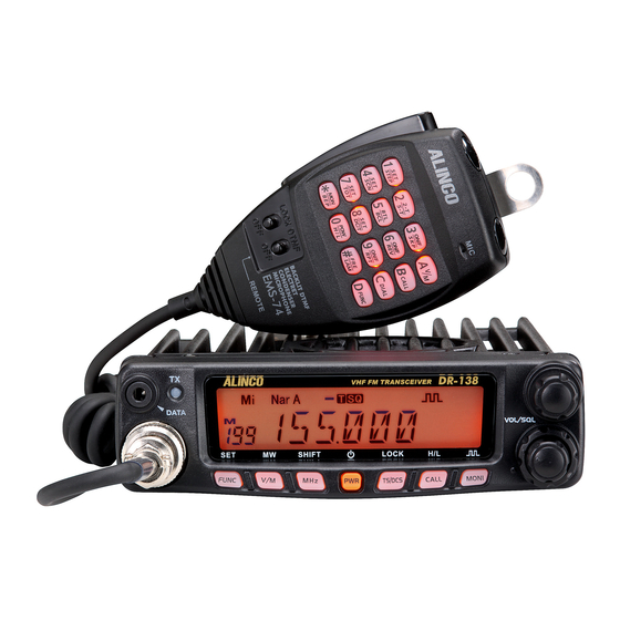
Page 16: Getting Acquainted
Getting Acquainted Front panel Microphone connection port Mic.connector Press key until icon appears then press the following key. NO. KEY FUNCTION FUNC/SET Confirms the selective functions and exit V/M/MW Stores data into channels MHz/SHIFT Sets offset direction and offset frequency TS/DCS/LOCK Sets Keypad lock function power... -
Page 17: Rear Panel
Getting Acquainted Rear panel NO. KEY Å FUNCTION (Not in use) Memory mode. Indicates the channel number in memory mode. Channel skip. Indicates the decimal point of frequency and the Decimal point scanning function. Indicates the frequency or memory name. Signal is being received or monitor. -
Page 18: Microphone
Getting Acquainted microphone MIC Connector Diagram(in the front view of connector) NO. KEY FUNCTION Increase frequency ,channel number or setting value. DOWN Decrease frequency, channel number or setting value. Push-To-Talk key to transmit. Numerical Keyd Input VFO frequencies and other various oprations DTMF ON/OFF Switches between DTMF and function operations. -
Page 19: Operating Mode
(As pic 1) In addition,the programming software is made available to B. Channel + Name Tag Mode: When dealers only and Alinco releases the software only to the set display as "NM", it enters into authorized importers. -
Page 20: Basic Operations
Basic Operations be masked. In this status, turn Main Dial or Microphone [ symbol stands for restricted or optional functions. Features and/ or operations may not be available to commercial-mode users unless ] key will increase or decrease frequency quickly by pre-programmed by the dealer. -
Page 21: Transmitting Tone Burst Tone
Basic Operations MEMORY CHANNEL PROGRAMMING Please hold the microphone approximately 2.5-5.0cm from your lips , and then speak into the microphone in your normal speaking voice. Under frequency mode (VFO), turn Main While transmitting, LED lights RED and TX-meter shows relative power level. Dial to select the desired frequency or Release PTT to receive. -
Page 22: Key Operations
KEY OPERATIONS squelch off/squelch off momeNTARY CTCSS/DCS Encode and Decode setup Many repeaters require a CTCSS tone Squelch Off: Press key to disable squelch, press key again or a DCS code encode setting as a “key” to resume squelch. This is set by programming software as an to access the system, so-called “selective- option. -
Page 23: Ctcss Scan
KEY OPERATIONS UP / DOWN keys) to enter the setting and return to original status. The T/SQ/DCS icon will remain on the display to show the current selective- calling status. To exit, simply use the TS/DCS key and press it until the relative status icon T/TQ/DCS disappears. -
Page 24: Keypad Lockout
KEY OPERATIONS means transmitting frequency higher than receiving frequency. While pressing and holding key, press key to enter the auto-dialer enquiry mode, LCD displays current default data When LCD displays " " icon, it indicates negative offset, which and current group displayed on left. If no data in current group,it means transmitting frequency lower than receiving frequency. -
Page 25: Parameter Setting Mode
PARAMETER SETTING MODE programming software. IMPORTANT: All or a part of operation in this chapter may not be available to dealer-programmed units. Press and hold key for over 2 The default setting list is available on P29. seconds to enter into setting menu. Press and hold key for over 2 seconds to enter the parameter Press... -
Page 26: Sending 2-Tone Call
PARAMETER SETTING MODE Turn Main Dial to select the desired 5-TONE group, Press [ PTT] to In 5Tone signaling mode,press for 2 seconds until LCD transmit selected group. displays "AN---",turn Main Dial to select desired digit(caller ID).In this mode, press to confirm existing digit and move cursor to Total:100groups,00-99,Default:00. -
Page 27: Power
PARAMETER SETTING MODE Turn Main Dial to select the desired setting. If select "SQ",it indicates you can hear the calling from caller when receive a matching carrier. TX Power (60W narrow) If LCD displays "CTC",it indicates you can hear the calling from caller when receive a matching carrier and CTCSS/DCS signaling . -
Page 28: Busy Channel Lockout
PARAMETER SETTING MODE Turn Main Dial to select the desired Editing Channel NAME (Available only in Memory mode) setting . In memory-mode, press and hold On:In current channel,Press PTT to for over 2 seconds to enter setting menu. transmit Press key to choose No.11 menu, LCD displays cursor and flashing. -
Page 29: Talk Around
PARAMETER SETTING MODE Talk Around Radio's DTMF SELF ID ENQUIRY By Talk Around function,you can directly communicate with other radios Press and hold key for over 2 seconds to enter general in your group in case the repeater is not activated or when you are out of setting menu. -
Page 30: Tot (Time-Out Timer)
PARAMETER SETTING MODE TOT (Time-out timer) DTMF Transmitting Time Press and hold key for over 2 TOT prohibits the users from transmitting after a certain period of time seconds to enter setting menu. has elapsed. When the time is over,transmitting stops and automatically returns to receiving. -
Page 31: Display Iiiumination Color Setting
General Setting Display iiiumination color setting Press key to choose No.24 menu, LCD displays "LAMP--25" This is to select the display illumination color. Turn Main Dial to select the desired LCD brightness; 1 to turn off, 32 to the brightest. Press and hold key for over 2 seconds to enter setting menu. -
Page 32: Pin Setup( Useless If Pin Is Not Assigned )
General Setting to next edition,press to clear out all This function may not be available in dealer-programmed units. digits. After finishing edition,press to confirm PIN Setup( Useless if PIN is not assigned and enter into edition of current group's ID corresponding name. Turn selector knob to select desired letter, press to move Enable this function,you have to insert a matching PIN to enter into... -
Page 33: Microphone Operation
Microphone Operation In this chapter, operations shown with is available to all units, is subject flashed in LCD, Press again to enable squelch and the icon disappears. to dealer-programming or restrictions. Some of features may be functional in memory mode temporary, but the setting will return to the initial parameters Switches between VFO and channel mode after changing channel or turned off the unit. -
Page 34: Scan Skip
Microphone Operation OFF: Busy channel lockout is disabled. This function can be temporarily used in channel mode. Once the Press number keys to confirm and exit. radio is turned off or switched to another channel, the temporary setting will be erased and back to initial settings. Reverse TX/RX Scan Skip TX frequency turns to RX frequency &... -
Page 35: Talk Around
Microphone Operation LCD displays T icon,it indicates CTCSS encode set in current Press number key to confirm and exit. channel. LCD displays T and SQ icon,it indicates CTCSS encode and decode set in current channel. LCD displays DCS icon,it indicates DCS encode and decode set in current channel. -
Page 36: Anti-Theft Alarm
Anti-theft Alarm By removing or cutting the cable before turning on will sound alarm. DC power cable To turn off the alarm, press PWR key to turn off the power. The alarm is canceled and turns on normally when PWR key is pressed next time. Optional alarm cable [UX1259] Steering-wheel etc. -
Page 37: Power
Cable Clone This feature clones the programmed data and parameters in the master unit to slave units. Use commonly available audio-cable with 3.5 mm stereo-mini plugs as shown below. Make a master unit by setting and programming it as desired. Turn off both units. -
Page 38: Maintenance
Maintenance Default Setting after Resetting Trouble Shooting Problem Possible Causes and Potential Solutions DCS encode DR-138HT and decode + and - polarities of power connection (a) Power is on, nothing are reversed. Connect red lead to plus DCS code 023N appears on Display. -
Page 39: Specifications
Specifications General Receiver (ETSI EN 300 086 standard testing ) Narrow band 144.000-147.995MHz Frequency Range Sensitivity ≤ 0.35μV (12dB Sinad) Adjacent Channel Number of Channels 200 channels ≥60dB Selectivity Intermodulation ≥60dB Channel Spacing 12.5KHz (Narrow band) Spurious Rejection ≥70dB Audio Response +1~-3dB(0.3~2.55KHz) Channel step 12.5KHz... -
Page 40: Appendix
Appendix 50 groups CTCSS Tone Frequency(Hz) 1024 groups DCS Code. 67.0 79.7 94.8 110.9 131.8 156.7 171.3 186.2 203.5 229.1 69.3 82.5 97.4 114.8 136.5 159.8 173.8 189.9 206.5 233.6 71.9 85.4 100.0 118.8 141.3 162.2 177.3 192.8 210.7 241.8 74.4 88.5 103.5 123.0 146.2 165.5 179.9 196.6 218.1 250.3 77.0 91.5 107.2 127.3 151.4 167.9 183.5 199.5 225.7 254.1... - Page 41 Appendix N is positive code, I is negative code, total: 1024groups.
- Page 42 This device complies with part 15 of the FCC rules. Operation is subject to the following two conditions: (1) this device may not cause harmful interference, and (2) this device must accept any interference received, including interference that may cause undesired operation. NOTE: This equipment has been tested and found to comply with the limits for a Class B digital device, pursuant to part 15 of the FCC Rules.
Need help?
Do you have a question about the DR-138HT and is the answer not in the manual?
Questions and answers