
Related Manuals for Brickcom Mini Box Series


Summary of Contents for Brickcom Mini Box Series
- Page 1 Megapixel Mini Box Network Camera Mini Box Series User’s Manual Quality Service Group...
- Page 2 Product name: Network Camera (MB series) Release Date: 2012/12 Manual Revision: V1.1 Web site: www.brickcom.com support@brickcom.com Email: info@brickcom.com © 2012 Brickcom Corporation. All Rights Reserved...
-
Page 3: Table Of Contents
Table of Contents Before You Use This Product ..................0 FCC Warning ........................0 Regulatory Information ....................1 Product Comparison ....................... Package Contents ......................0 Cube Network Camera Overview ..................2 Device Appearance Description ..................4 LED Behavior ........................5 Installation ........................ -
Page 4: Before You Use This Product
Before You Use This Product In many countries, there are laws prohibiting or restricting the use of surveillance devices. This Network Camera is a high-performance, web-ready camera which can be part of a flexible surveillance system. It is the user’s responsibility to ensure that the operation of this camera is legal before installing this unit for its intended use. -
Page 5: Regulatory Information
Regulatory Information Federal Communication Commission Interference Statement This equipment has been tested and found to comply with the limits for a Class B digital device, pursuant to Part 15 of the FCC Rules. These limits are designed to provide reasonable protection against harmful interference in a residential installation. -
Page 6: Product Comparison
Product Comparison Model Name Lesns WiFi USB port for 3G/ 4G IR LED Board MB-X00Ap Lens Series Board WMB-X00Ap Lens *This table compliant with (W)MB-500A, (W)MB-400A, (W)MB-300A, (W)MB-200A, (W)MB-130A. Package Contents Please check to make sure the product package contains all the accessories listed below. - Page 7 e. Warranty Card f. Power Adapter (Only for WMB series) g. Terminal I/O Connector Block - 1 -...
-
Page 8: Cube Network Camera Overview
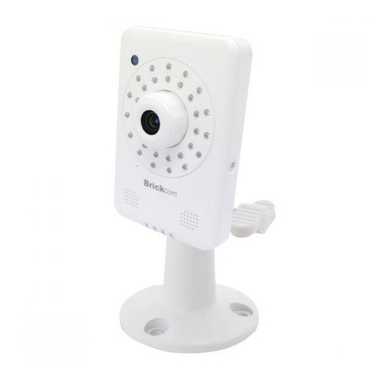
Mini Box Network Camera Overview The compact Brickcom MB series Mini Box network series offers a high quality, video surveillance solution for residences and small businesses. Unlike a general webcam, this camera series is a standalone surveillance system that does not need to be connected to a computer. - Page 9 - 3 -...
-
Page 10: Device Appearance Description
Device Appearance Description < Front & Rear view > Power LED Adjustable focal Lens Ethernet RJ45 Socket Light Sensor Power Connector Illumination LED Reset Button Built-in Microphone DIDO Terminal I/O Connector Speaker WPS Button (*) Privacy LED Privacy Button WPS LED (*) FW Upgrade LED Micro SD/SDHC slot Wireless LED (*) -
Page 11: Led Behavior
LED Behavior Function LED Behavior Description Remark Normal Operation Power Continuous Illumination (Blue) Power Unlit Powered off (Blue) 1. Connected to switch by Status Continuous Illumination Second (Blue) Ethernet or WiFi. 1. Powered off Status Unlit Second (Blue) 2. No connection 1. - Page 12 Hardware Reset Reset Button MB Series The Reset Button can be used to reboot the camera or restore it to factory default settings. If the camera experiences a problem, rebooting the camera may correct the problem. If the problem remains, please restore the camera to factory default settings and reinstall the software.
-
Page 13: Installation
Installation System Requirements Operating System: Microsoft Windows XP Home Edition SP2 Microsoft Windows XP Professional SP2 Computer: IBM PC/AT Compatible CPU: Pentium 3GHz or faster Memory: 1024 MB or more Monitor: 1024 x 768 pixels or more, 24-bit True color or better Network Interface: 10/100Mbps Network interface card must be installed Web Browser:... -
Page 14: Camera Connection
Camera Connection Warning Hot – Please attach the bracket before using. Basic Connection 1. Connect the supplied power cable from the camera to a power outlet. 2. Connect the camera to a switch using an Ethernet cable. When powering up, the power LED will light up and the camera will boot up. The Wireless &... - Page 15 Wireless Connection (Only for WMB series) Connect the supplied power cable from the camera to a power outlet. And press WPS button both on the camera and the wireless router (DWRT-600N). Terminal I/O Connector Block Connection Attach the supplied connector block to the terminal connector on the camera. Refer to the diagram below to attach external devices to the connector block.
-
Page 16: Software Installation
1. Insert the Installation CD into the CD-ROM driver. Run Auto-Run Tool directly from the CD-ROM to start the installation. When installing the Brickcom software kit for the first time, select a desired language for the interface. The available languages are listed in the scroll box. - Page 17 2. In the Install Shield Wizard dialog box, click <Next> to continue. 3. Read the End-User License Agreement and check the option “I accept the terms of the license agreement”. Click <Next> to continue. - 11 -...
- Page 18 4. Click <Change> to change the appointed folder where installation and program files will be stored. Click <Next> to continue. 5. Select to create shortcuts. Click <Next> to continue. - 12 -...
- Page 19 6. Select the application and click <Finish>. When launching the PC-NVR program, please refer to the PC-NVR user manual - 13 -...
-
Page 20: Easyconfig
C:\Program Files\Brickcom\EasyConfig unless the program was saved to a preferred directory. 1. Click <Start> to continue. The program will automatically search for the camera in the intranet. NOTE - Check “Skip the hardware installation guide” to skip checking the hardware connection. - Page 21 - 15 -...
- Page 22 2. Select either “Simple Mode” or “Professional Mode” to obtain the camera’s IP settings. If “Simple Mode” is selected, EasyConfig will set up the connection automatically. If “Professional Mode” is selected, the user will need to configure the IP settings manually. - 16 -...
- Page 23 3. There may be many cameras in the local network. Differentiate the cameras using their UPnP name. Double click on the camera from the survey list to connect. 4. Enter the username and password of the camera. For first time use, the default username and password are “admin/admin.”...
- Page 24 5. For configuring the IP address settings, select either <Settings remain the same>, <Automatically obtain an IP Address (DHCP)> or <Set IP Address configuration manually>. The DHCP setting is recommended. a. If <Set IP Address configuration manually> is selected, the following pages will be displayed.
- Page 25 6. If the camera supports the EasyLink function, the following page will be displayed. Otherwise, this page will not be shown. *If desired, click <Skip> to skip this setting. - 19 -...
- Page 26 EasyLink is a unique Brickcom function which allows users to assign a unique EasyLink name to their network camera’s IP address. There is no need to configure the router to open up ports or remember hard-to-memorize IP addresses. When this feature is enabled, users can log onto [uniqueEasyLinkname].mybrickcom.com to view the camera’s web GUI and live...
- Page 27 b. If “Static IP address settings” was selected, the failure page will be displayed as below: c. If the connection was successful, the user will see the message: “Congratulations. The installation of the camera is complete.” When this window is displayed, click <PC-NVR> to start the PC-NVR program, <Live View>...
-
Page 28: Accessing The Network Camera
Accessing the Network Camera Check Network Settings The camera can be connected either before or immediately after the software installation. The Administrator should complete the network settings on the configuration page, including entering the correct subnet mask and IP address of gateway and DNS. Ask the network administrator or Internet service provider for the detail information.
Need help?
Do you have a question about the Mini Box Series and is the answer not in the manual?
Questions and answers