
Related Manuals for Planet GS-4210-8P2T2S


Summary of Contents for Planet GS-4210-8P2T2S
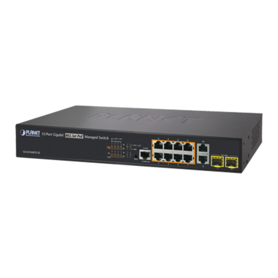
- Page 1 8-Port 10/100/1000T 802.3at PoE + 2-Port 10/100/1000T + 2-Port 100/1000X SFP Managed Switch GS-4210-8P2T2S Quick Installation Guide...
-
Page 2: Table Of Contents
Table of Contents 1. Package Contents ..................3 2. Requirements ..................... 4 3. Terminal Setup ................... 5 4. Logon to the Console .................. 6 5. Configuring IP Address via the Console ............7 6. Saving the Configuration via the Console ............9 7. Starting Web Management .................10 8. Saving Configuration via the Web ...............12 9. Recovering Back to Default Configuration .............13 10. -
Page 3: Package Contents
1. Package Contents Thank you for purchasing PLANET 8-Port 10/100/1000T 802.3at PoE + 2-Port 10/100/1000T + 2-Port 100/1000X SFP Managed Switch, GS-4210-8P2T2S. “Managed Switch” mentioned in this Guide refers to the GS-4210-8P2T2S. Open the box of the Managed Switch and carefully unpack it. The box should contain the following items:... -
Page 4: Requirements
2. Requirements z Workstations running Windows XP/2003/Vista/7/8/2008, MAC OS X or later, Linux, UNIX, or other platforms are compatible with TCP/IP protocols. z Workstations are installed with Ethernet NIC (Network Interface Card) z Serial Port Connection (Terminal) The above Workstations come with COM Port (DB9) or USB-to-RS-232 converter. The above Workstations have been installed with terminal emulator, such as Hyper Terminal included in Windows XP/2003. -
Page 5: Terminal Setup
3. Terminal Setup To configure the system, connect a serial cable to a COM port on a PC or notebook computer and to the RJ45 type of the console port of the Managed Switch. PC / Workstation with Terminal Emulation Software Managed Switch RS-232 to RJ-45 Cable Serial Port... -
Page 6: Logon To The Console
4. Logon to the Console Once the terminal is connected to the device, power on the Managed Switch, and the terminal will display “running testing procedures”. Then, the following message asks to log-in user name and password. The factory default user name and password are shown as follows, and the login screen in Figure 4-1 appears. -
Page 7: Configuring Ip Address Via The Console
5. Configuring IP Address via the Console The WGSW Managed Switch is shipped with default IP address as follows: IP Address: 192.168.0.100 Subnet Mask: 255.255.255.0 To check the current IP address or modify a new IP address for the Switch, please use the procedures as follows: Show the current IP address 1. At the “GS-4210-8P2T2S#” prompt, enter “show ip”. 2. The screen displays the current IP address, Subnet Mask and Gateway as shown in Figure 5-1. Figure 5-1: IP Information Screen... - Page 8 Configuring IP address 3. At the “GS-4210-8P2T2S#” prompt, enter “configure”. 4. At the “GS-4210-8P2T2S(config)#” prompt, enter the following command and press <Enter> as shown in Figure 5-2. GS-4210-8P2T2S(config)# ip address 192.168.1.100 mask 255.255.255.0 GS-4210-8P2T2S(config)# ip default-gateway 192.168.1.254 The previous command would apply the following settings for the Switch. IP Address: 192.168.1.100 Subnet Mask: 255.255.255.0 Gateway: 192.168.1.254 Figure 5-2: IP Address Screen 5. Repeat Step 1 to check if the IP address is changed. If the IP is successfully configured, the WGSW Managed Switch will apply the new IP address setting immediately. You can access the Web interface of the WGSW...
-
Page 9: Saving The Configuration Via The Console
RAM to FLASH by writing the command or copying the running-config startup- config command, so that the running configuration sequence becomes the startup configuration file, which is called configuration save. 1. At the “GS-4210-8P2T2S#” prompt, enter “copy running-config startup- config” as shown in Figure 6-1. Figure 6-1: The Configuration Screen... -
Page 10: Starting Web Management
7. Starting Web Management The following shows how to start up the Web Management of the Managed Switch. Note the Managed Switch is configured through an Ethernet connection. Please make sure the manager PC must be set on the same IP subnet address. For example, the default IP address of the Managed Switch is 192.168.0.100, then the manager PC should be set at 192.168.0.x (where x is a number between 1 and 254, except 100), and the default subnet mask is 255.255.255.0. - Page 11 3. After entering the password, the main screen appears as Figure 7-3 shows. Figure 7-3: Web Main Screen of Managed Switch The Switch Menu on the left of the Web page lets you access all the commands and statistics the Managed Switch provides. Figure 7-4: Switch Menu Now, you can use the Web management interface to continue the Switch management.
-
Page 12: Saving Configuration Via The Web
8. Saving Configuration via the Web In the Managed Switch, the running configuration file stores in the RAM. In the current version, the running configuration sequence of running-config can be saved from the RAM to FLASH by “Save Configurations to FLASH” function, so that the running configuration sequence becomes the startup configuration file, which is called configuration save. -
Page 13: Recovering Back To Default Configuration
10 seconds. After the device is rebooted, you can login the management Web interface within the same subnet of 192.168.0.xx. Switch PoE In-Use 10 12 1000 RESET Figure 9-1: GS-4210-8P2T2S Reset Button... -
Page 14: Customer Support
PLANET online FAQ: http://www.planet.com.tw/en/support/faq.php?type=1 Switch support team mail address: support_switch@planet.com.tw GS-4210-8P2T2S User’s Manual: http://www.planet.com.tw/en/support/download.php?type1=1&model=48564&type=3#list Copyright © PLANET Technology Corp. 2014. Contents are subject to revision without prior notice. PLANET is a registered trademark of PLANET Technology Corp. All other trademarks belong to their respective owners. - Page 15 This page is intentionally left blank...
- Page 16 This page is intentionally left blank...
Need help?
Do you have a question about the GS-4210-8P2T2S and is the answer not in the manual?
Questions and answers