Table of Contents
Advertisement
Quick Links
Advertisement
Table of Contents

Related Manuals for Dahua Technology 8A840WANF


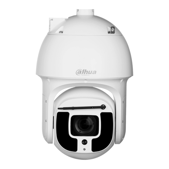
Summary of Contents for Dahua Technology 8A840WANF
- Page 1 8A840WANF Quick Installation Guide V1.0.1 Dahua Technology Co., Ltd...
-
Page 2: Foreword
Foreword General This manual offers reference material and general information about the basic operation, maintenance, and troubleshooting for a Dahua Network Camera. Read, follow, and retain the following safety instructions. Heed all warning on the unit and in the operating instructions before operating the unit. - Page 3 About the Guide This user guide has been compiled with great care and the information it contains has been thoroughly reviewed and verified. The text was complete and correct at the time of printing. This guide may be periodically ...
- Page 4 Legal Notices Copyright This user guide is ©2017, Dahua Technology Company, LTD. This user guide is the intellectual property of Dahua Technology Company, LTD and is protected by copyright. All rights reserved. Trademarks All hardware and software product names used in this document are likely to be registered...
-
Page 5: Important Safeguards And Warnings
Important Safeguards and Warnings This chapter describes the contents covering proper handling of the device, hazard prevention, and prevention of property damage. Read these contents carefully before using the device, comply with them when using, and keep it well for future reference. Installation and Maintenance Professionals Requirements All installation and maintenance professionals must have adequate qualifications or ... - Page 6 An object has fallen on the unit. The unit has been dropped and the housing is damaged. The unit displays a marked change in performance. The unit does not operate in the expected manner when the user correctly follows the proper operating procedures.
- Page 7 Do not touch the CCD or the CMOS optic sensor. Use a blower to clean dust or dirt on the lens surface. Use a dry cloth dampened with alcohol and gently wipe away any dust on the lens. Use a dry soft cloth to clean the unit’s housing. If the unit is particularly dusty, use water to ...
-
Page 8: Cybersecurity Recommendations
Cybersecurity Recommendations Mandatory actions to be taken towards cybersecurity Change Passwords and Use Strong Passwords The number one reason systems get “hacked” is due to having weak or default passwords. It is recommended to change default passwords immediately and choose a strong password whenever possible. - Page 9 Change ONVIF Password Older IP camera firmware does not automatically change the ONVIF password when the system credentials are changed. Update the camera’s firmware to the latest revision or manually change the ONVIF password. Forward Only Ports You Need ...
- Page 10 Connect IP Cameras to the PoE Ports on the Back of an NVR Cameras connected to the PoE ports on the back of an NVR are isolated from the outside world and cannot be accessed directly. Isolate NVR and IP Camera Network ...
-
Page 11: Table Of Contents
Table of Contents Foreword ..............................I Important Safeguards and Warnings ....................IV Cybersecurity Recommendations ......................VII Table of Contents ............................. X 1 Unpacking .............................. 1 Parts List ............................1 2 Installation and Configuration ......................2 Framework and Dimension ......................2 Wiring ............................ -
Page 12: Unpacking
Unpacking This equipment should be unpacked and handled with care. If an item appears to have sustained damage during shipping, notify the shipper immediately. Verify that all the parts listed below are included. If an item is missing, contact customer support or your local representative. -
Page 13: Installation And Configuration
Installation and Configuration Framework and Dimension Use this process to plan, install, and configure the security network and the IP devices. Figure 2-1: 6CE445XANR Dimension Installation and Configuration 2... - Page 14 Figure 2-2: PFB306W Dimensions Installation and Configuration 3...
-
Page 15: Wiring
Wiring Figure 2-3: Cable Detail Label Function Wire Color Connection 24 VAC (positive) Power Input Yellow/Green Earth Ground Black 24 VAC (negative) Yellow RS485 + RS485 Orange RS485 - Analog Video Output — BNC (1.0 Vp-p, 75 Ω) — Network —... -
Page 16: Alarm Setup
Alarm Setup Certain devices support alarm inputs and outputs, check your specific device for alarm capability. 2.3.1 Alarm Input Refer to the figure below for alarm input configuration. The device collects that status of the alarm input port when the input signal is idle or grounded. If the input signal is connected to the 3.3 V or it is idle then the device receives the alarm input signal. -
Page 17: Alarm Output - Switch Application
2.3.3 Alarm Output – Switch Application The alarm output drives the external circuit, with a maximum current of 30 mA and a maximum voltage of 5 V. It is recommended to add a relay if the circuit exceeds the maximum values. Figure 2-6: Alarm Output Switch Application Diagram Locally Storing Data Certain cameras include a SDHC card slot for onboard storage that support a 128 GB Micro... -
Page 18: Camera Installation
Camera Installation This section details installing the camera to a solid wall or to a ceiling, in an outdoor or an indoor environment. Note that the wall or ceiling must be capable of supporting a minimum of eight (8) times the weight of the camera and a bracket (if used). DO NOT connect the camera to the power supply during installation. -
Page 19: Preparing The Camera
Preparing the Camera The Network PTZ camera comes with the PFB306W Wall Mount, the installer must supply the following hardware: Four (4) bolts, washers or other fastening hardware to secure the wall mount to the installation medium. The hardware must be capable of supporting eight (8) times the weight of the camera and mount. -
Page 20: Mounting The Camera To A Wall
Mounting the Camera to a Wall Place the Wall Mount against the wall and mark the location of the center hole and mark the four (4) perimeter mounting holes. Pre-drill the four perimeter holes as marked on the wall for the expansion bolts, using a drill bit that is no wider than the expansion bolt. - Page 21 Connect the incoming cables routed through the wall mount to the corresponding power, Ethernet, audio, and alarm cables from the dome composite cable. Caution: Connect the Earth Ground cable to the YELLOW/GREEN cable (contained in the VAC Power bundle) to ensure the camera is well grounded. Pull the connected cables into the wall mount bracket with care.
-
Page 22: Network Configuration
Network Configuration Dahua IP cameras feature a built-in Web interface to control all aspects of camera operation. This section includes details about the supported network protocols, configuring IP addresses, and configuring alarms and local recording options. Refer to the camera’s Operations Manual for full details. -
Page 23: Modifying The Ip Address
Modifying the IP Address To operate the camera in your network you must assign it a valid network IP address. The default IP address is 192.168.1.108, but you may have to change this address if it conflicts with another device on the network. To properly configure the camera for your network, you need the following information: Camera IP address –... -
Page 24: Accessing The Web Interface
Click the Net icon at the top of the ConfigTool. Modify the IP Address and any other applicable network parameter. Click Save to finish modification and store the modified network parameters. Accessing the Web Interface Each camera can be accessed directly from the Internet Explorer Web browser. The Web Interface allows you to set camera parameter, configure alarm inputs and outputs, view live camera images, and review recorded video. -
Page 25: Configuring Alarms
Configuring Alarms The device’s Web Interface offers a Relay Activation page to configure alarms and to set alarm responses. Figure 4-1: Alarm Configuration Access the Web Interface for the device and click the Setup tab. Expand the Event menu, then choose the Alarm page. Set the alarm input and output parameters in the Relay Activation page. -
Page 26: Configuring Local Sd Card Recording
Configuring Local SD Card Recording The devices Web interface contains settings to control the recording medium and to configure an alarm that triggers once the Micro SD card passes a pre-determined storage. Access the Web Interface for the device and click the Setup tab. Expand the Storage menu, then choose the Destination page. - Page 27 Check the Relay-out box to enable a relay alarm. Then, specify the time in seconds to delay the alarm relay output (10 s to 300 s). Check the Send Email box to send an email to a specified user after the device triggers an alarm.
- Page 28 Dahua Technology USA 23 Hubble Irvine, CA 92618 Tel: (949) 679-7777 Fax: (949) 679-5760 Support: 877-606-1590 Sales: sales.usa@dahuatech.com Support: support.usa@dahuatech.com © 2019 Dahua Technology USA. All rights reserved. Design and specifications are subject to change without notice.