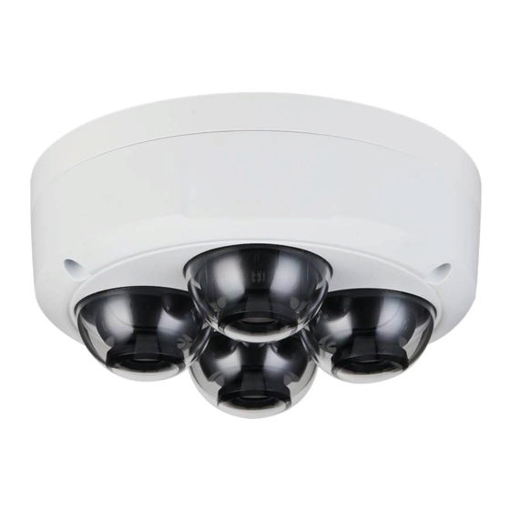
Summary of Contents for Dahua Technology IPC-PDB4830-B360
- Page 1 Multi i-sen sor D Dome e Ne etwor k Ca amera Quick k Start Guide V1.0. HEJIANG DAHUA VI ISION TEC CHNOLOG GY CO., LT...
- Page 2 Forew word General his Quick S Start Guide (hereinafte er referred t to as "the Guide") int roduces the e functions, stallation an nd operation s of the cam mera. Safety In nstruction he following categorized d signal word ds with defin ned meaning g might app pear in the gu...
-
Page 3: Foreword Ii
All the designs and software are subject to change without prior written notice. The product updates might cause some differences between the actual product and the Guide. Please contact the customer service for the latest program and supplementary documentation. ... -
Page 4: Important Safeguards And Warnings
Important Safeguards and Warnings Electrical safety All installation and operation should conform to your local electrical safety codes. The power source shall conform to the Safety Extra Low Voltage (SELV) standard, and supply power with rated voltage which conforms to Limited power Source requirement according to IEC60950-1. - Page 5 protection n effect. It is reco mmended c connect the grounding h hole to the g ground to en nhance the reliability of the devic Do not to ouch the ima age sensor directly (CM MOS). Dust and dirt cou uld be remo ved with air blower, o...
- Page 6 egulat tory In nform mation FCC Info ormation hanges or m modification ns not expre essly appro ved by the party respo onsible for compliance ould void the e user's auth hority to ope erate the equ uipment. FCC condi itions: his device c omplies with...
-
Page 7: Table Of Contents
Table of Contents Foreword ..............................I Important Safeguards and Warnings ..................... I Regulatory Information ........................IV 1 Introduction ............................1 1.1 Cable ............................1 1.2 Connecting Alarm Input/output ....................1 2 Network Configuration ........................4 2.1 Initializing Device ......................... 4 2.2 Modifying Device IP Address ....................... - Page 8 Intr roduc ction 1.1 Ca able Cable typ pe might var ry with differ rent devices , and the ac ctual product t shall preva ail. Please w waterproof a all the cable e joints with insulating t tape and wa aterproof ta ape to avoid...
- Page 9 Port Port Na Function ALARM _OUT_ When conne ecting to ala arm device, only the A ALARM_OUT T port and ALARM_OUT T_GND po ort with the e same nu umber can be used ogether. Receives the e switch sign nal of extern nal alarm sou urce.
-
Page 10: Introduction
Figure Alarm o output tep 3 Log in n web interfa ace, and con nfigure alarm m input and alarm outpu ut in alarm s setting. The alarm in put in the w web interface e is correspo onding to the e alarm inpu ut end of the ... - Page 11 Netw work Conf figura ation evice initializ zation and I P setting ca an be finishe ed with the "C ConfigTool" or in web in nterface. For ore informat tion, see the e WEB opera ration manua Device in nitialization i is available on select m models, and...
- Page 12 All the e devices fo und in the n network segm ment are list ted. tep 5 Selec ct one or sev veral devices s which Sta tus are Uni nitialized, a and then clic ck Initialize. The D Device initia alization inte erface is dis splayed.
-
Page 13: Installation
sure t they are the e same as what you s et during in itialization, otherwise th here will be "wron ng password d" notice. tep 2 Selec ct the device es which IP a addresses n need to be m modified, and d then click Modify IP. - Page 14 gure 2-4 ain interface able 2-1 Ico I I con nction Descriptio You can zo oom video im mage with tw wo operation Click t the icon, an d then sele ect an area in the video o image to zoom i in;...
-
Page 15: Dimension
nstalla ation 3.1 Pa acking List The tool r required for the installat tion such as s electric dril l is not prov vided in the p packing. The oper ration manu al and relate ed tool are contained in n the disk or r the QR co ode, and the e... - Page 16 3.3 Ins stalling g Devic 3.3.1 In nstallati on met 3.3.2 In nstalling g SD Ca ard (Opt tional) ull the powe er plug off be efore installin ng or remov v ing the SD c c ard.
-
Page 17: Attaching Device
3.3.3 A Attachin g Devic ake sure th he mounting surface is strong enou ugh to hold at least thr ree times of f the device e eight. Cable goin ng through the mounti ing surface... - Page 18 Cable goin n g through the side ca a ble tray...
- Page 19 3.3.4 In nstalling g Water rproof C Connect his part is o only needed d when there e is waterp roof connec c tor come w w ith the dev v ice and the e evice is used d outdoor.
-
Page 20: Adjusting Angle
3.3.5 A A djusting Angle e... - Page 21 Zhejiang D ahua Vision n Technology y Co., Ltd Address:N No.1199 Bin n’an Road, B Binjiang Dist trict, Hangzh h ou, PRC. Postcode: 3 310053 Tel: +86-57 71-87688883 Fax: +86-5 71-8768881 Email:overs seas@dahu uatech.com Website: www.dahuase ecurity.com...


Need help?
Do you have a question about the IPC-PDB4830-B360 and is the answer not in the manual?
Questions and answers