Table of Contents
Advertisement
Quick Links
Advertisement
Table of Contents

Related Manuals for PRO SIGNAL PSG3455


Summary of Contents for PRO SIGNAL PSG3455
- Page 1 HDBitT HDMI EXTENDER MATRIX PSG3455...
-
Page 2: Important Safety Information
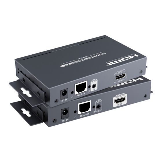
Please read these instructions carefully before use and retain for future reference. IMPORTANT SAFETY INFORMATION When using electrical appliances basic safety precautions should always be followed. • To prevent fire or shock hazard, do not expose this product to rain or moisture. •... - Page 3 OVERVIEW TRANSMITTER IR receiver window - Receiver IR signal from remote control. Power indicator - LED for power on indication. TX indicator - Indicates current transmission channel ID. Reset Button Power input - connect the PSU 5VDC connector. Data transmission indicator. RJ45 output connector.
-
Page 4: Matrix Configuration
RECEIVER INSTALLATION MATRIX CONFIGURATION POINT TO POINT CONFIGURATION OPERATION IR User Guide: • IR receiver extension cable should be connected to the IR IN port of the receiver. • The IR emitter extension cable should be connected to the IR OUT port of the transmitter. - Page 5 Button Control: • There is a "TX ID" display on the transmitter, and there are both TX CONNECTED and RX ID displays on the receiver unit, each of which has a 2 digit display plus 2 adjacent buttons which adjust each digit. •...
- Page 6 IP setting • TX and RX units have their own default IP address, TX's IP is 192.168.1.238, and RX's IP is 192.168.1.239. Generally, it is not need to change the device IP address, as the system can work normally even though multiple TX units and multiple RX units connected into the system with their default IP address.
- Page 7 Device scanning and setting • Device scanning and setting (example shown of TX's setting only, RX's setting is identical) Figure 3 Device Name setting • Click on a default device name and enter the desired name in the pop-up box. Figure 4...
- Page 8 Device Channel setting • Select the channel for the device using the scroll list. Figure 5 • Click the Update button when complete to store all the settings made. Mode setting • Click on the Mode button to change the required mode name. Figure 6 •...
- Page 9 Selecting the operation Mode • Click on the Mode button to change to the required mode and switch to the settings stored previously under that name.
-
Page 10: Specifications
SPECIFICATIONS Voltage/Current DC 5V 2A Power consumption TX: <4W RX: <4W HDMI compliance HDMI 1.3 HDCP compliance HDCP 1.4 HDMI input resolution 480i@60Hz, 480p@60Hz, 576i@50Hz, 576i@50Hz, 576p@50Hz, 720p@50/60Hz, 1080i@50/60Hz, 1080p@50/60Hz HDMI output resolution 1080p@60Hz Audio formats Max transfer rate 18Mbps Input/output TMDS signal 0.7~1.2Vp-p Input/output DDC signal... - Page 12 INFORMATION ON WASTE DISPOSAL FOR CONSUMERS OF ELECTRICAL & ELECTRONIC EQUIPMENT. When this product has reached the end of its life it must be treated as Waste Electrical & Electronic Equipment (WEEE). Any WEEE marked products must not be mixed with general household waste, but kept separate for the treatment, recovery and recycling of the materials used.
Need help?
Do you have a question about the PSG3455 and is the answer not in the manual?
Questions and answers