Table of Contents
Advertisement
Quick Links
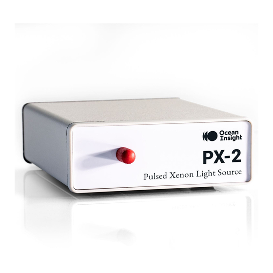
PX-2
Pulsed Xenon Light Source
Installation and Operation Instructions
Description
The PX-2 Pulsed Xenon Light Source is a high flash rate, short-arc xenon lamp for applications
involving absorbance, reflection, fluorescence and phosphorescence measurements, and especially for
measuring optically or thermally labile samples.
The PX-2 has an SMA 905 Connector that couples to Ocean Optics miniature fiber optic
spectrometers and accessories, including optical fibers, cuvette holders, probes and other sampling
optics.
The PX-2 operates at speeds up to 220 Hz, offers excellent pulse-to-pulse stability, and has two trigger
modes for software control of the flash rate. Any external TTL positive pulse can be used to trigger the
PX-2. When it is coupled to a spectrometer, you can easily synchronize operation of both the light and
detector.
Because it produces a pulsed signal, the PX-2 is less likely to contribute to solarization in optical fiber
assemblies, which can occur when fibers are illuminated with signals less than 260 nm.
For an example of a phosphorescence application using the PX-2 with an Ocean Optics spectrometer
and an HR4-BREAKOUT Box, see Configuring Ocean Optics Spectrometers for Phosphorescence
Measurements in the Engineering Documents at www.oceanoptics.com.
110-00000-000-01-201408
1
Advertisement
Table of Contents

Summary of Contents for Ocean Optics PX-2
- Page 1 The PX-2 operates at speeds up to 220 Hz, offers excellent pulse-to-pulse stability, and has two trigger modes for software control of the flash rate. Any external TTL positive pulse can be used to trigger the PX-2. When it is coupled to a spectrometer, you can easily synchronize operation of both the light and detector.
-
Page 2: Parts Included
Do not drop the instrument, as this may cause permanent damage to the unit. Handle with care. Connecting the PX-2 The set-up procedure differs, depending on the spectrometer to which you are connecting the PX-2. Connecting to a USB2000/USB2000+/USB4000/HR2000 Spectrometer The USB2000 and HR2000 Spectrometers have a 10-pin connector. - Page 3 (A1 and A2 on the right) when plugging in the adapter. 3. Tighten the jackscrew to hold the adapter in place. 4. Connect the DB15 cable that came with your PX-2 to the USB-ADP-PX2 Adapter, then to your PX-2 light source.
- Page 4 2. Turn the PX-2 on via the power switch on the rear of the unit. 3. Select Multiple or Single TTL mode by moving the toggle switch on the rear panel of PX-2. You must also configure this mode in the operating software. See TTL Mode Information below.
-
Page 5: Single Mode
In Single mode, a single lamp flash occurs during each integration period. You can modify the flash rate by changing the integration period. Since the PX-2 has a maximum repetition rate of 220 Hz, the minimum integration time allowed in Single mode is 5 milliseconds. - Page 6 PX-2 Installation and Operation Instructions 2. Check the Single Strobe option. 110-00000-000-01-201408...
- Page 7 PX-2 Installation and Operation Instructions 3. Click the Main Controls tab to go back to the Main Controls. 4. Set the PX-2 Flash Mode switch (on the back of the PX-2) to Single mode to flash the lamp once per integration period.
- Page 8 Controlling the PX-2 in OceanView with Continuous Strobe The Continuous Strobe control in OceanView is used to adjust the PX-2 lamp intensity per integration period. Note The following procedure can also be performed in OceanView using the Graph View.
- Page 9 PX-2 Installation and Operation Instructions ► Procedure 1. Add the Continuous Strobe control to the Main Controls tab of the Acquisition Controls. To do this, click the Add/Remove Controls tab in the Acquisition Parameter Controls. 2. Check the Continuous Strobe option.
- Page 10 PX-2 Installation and Operation Instructions 3. Click the Main Controls tab to go back to the Main Controls. 4. Set the PX-2 Flash Mode switch (on the back of the PX-2) to flash the lamp multiple times per integration period.
- Page 11 PX-2 Installation and Operation Instructions Note If incorrect settings are used for the measurements, some spectra will be collected when the lamp is flashing and others when the lamp is not flashing, or spectra may be acquired with an inconsistent number of pulses per integration cycle. Improper settings will cause variability in the results.
-
Page 12: Specifications
5 microseconds (at 1/3 height of pulse) Aperture 3 mm Connector SMA 905 Lifetime pulses (estimated 230 days continuous operation) PX-2 Pinout Information The following section contains information on the 15-pin connector on the PX-2. Pin Number Description Single strobe Continuous strobe Ground 110-00000-000-01-201408... - Page 13 2. Plug the 12 VDC power supply into a wall outlet, then connect the barrel connector on the power supply to the rear of the PX-2. 3. Connect the 15-pin cable to the rear of the PX-2, and then connect the other end to the 15-pin connector on the S2000 Spectrometer.
- Page 14 PX-2 Installation and Operation Instructions Frequency (Hz) JP3 Post # Function ADC500/SAD500 ADC1000 DAQ700 ADC2000-PCI Not enabled – Reserved for future software control Divide by 2 Too fast Too fast Too fast Divide by 2 Too fast Too fast Divide by 2 Divide by 2 15.2...


Need help?
Do you have a question about the PX-2 and is the answer not in the manual?
Questions and answers