
Subscribe to Our Youtube Channel
Related Manuals for Metrohm 762 IC Interface


Summary of Contents for Metrohm 762 IC Interface
- Page 1 762 IC Interface 762 IC Interface Metrohm Metrohm SYSTEM 1 RUN/ STOP RUN/ SYSTEM 2 STOP STOP METROHM Ltd. 8.762.1003 CH-9101 Herisau Instructions for Use Switzerland Phone ++41 71 353 85 85 ++41 71 353 89 01...
- Page 2 CH-9101 Herisau/Switzerland Tel. ++41 71 353 85 85 ++41 71 353 89 01 Internet www.metrohm.ch E-Mail info@metrohm.ch 762 IC Interface 762 IC Interface Metrohm Metrohm SYSTEM 1 RUN/ STOP RUN/ SYSTEM 2 STOP STOP 8.762.1003 Instructions for Use 16.02.2000 / dö...
-
Page 3: Table Of Contents
2.4.9 761 Compact IC ................20 3 Operation ....................Manual operation..................21 Operation via «IC Net»................22 3.2.1 Settings in the "762 IC Interface" window ........22 3.2.2 Event output lines ................ 25 4 Appendix ....................Technical data..................29 Scope of delivery..................32 Optional accessories................33 Warranty and conformity ...............34... - Page 4 Table of contents List of figures Fig. 1: Connection possibilities at 762 IC Interface ........... 1 Fig. 2: Front of 2.762.0010 IC Interface ..............2 Fig. 3: Rear of 2.762.0010 IC Interface ..............3 Fig. 4: Front of 2.762.0020 IC Interface ..............4 Fig.
-
Page 5: Introduction
The 762 IC Interface provides the connection between the PC and external IC or HPLC peripheral instruments. Up to 16 instruments in- cluding 4 detectors can be connected to the 762 IC Interface and con- trolled either uniformly or independently by means of the «IC Net» PC software. -
Page 6: Parts And Controls
1 Introduction Parts and controls 1.2.1 2.762.0010 IC Interface 762 IC Interface Metrohm Metrohm SYSTEM 1 RUN/ STOP Fig. 2: Front of 2.762.0010 IC Interface Mains switch Run/Stop key for System 1 For switching the instrument RUN: Manual start of a determi-... -
Page 7: Fig. 3: Rear Of 2.762.0010 Ic Interface
1.2 Parts and controls Made by Metrohm Herisau Switzerland System 1 Events Type 1.762.0020 Nr. 100 - 240 V 1 2 3 4 5 6 7 Start f = 50-60 Hz P = 7 W Dev. 1/5 Dev. 2/6 Dev. 3/7 Dev. -
Page 8: 2.762.0020 Ic Interface
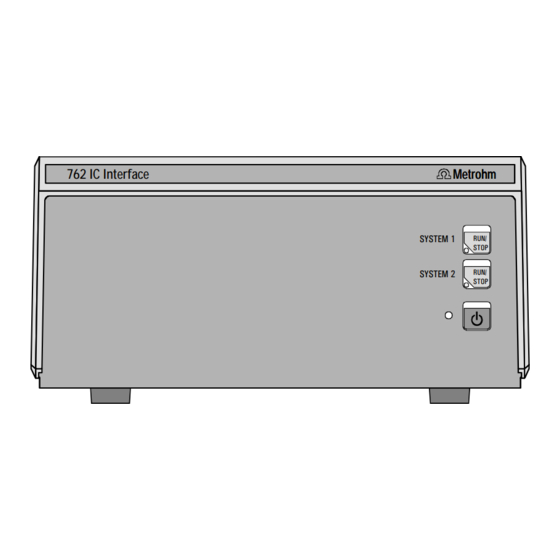
1 Introduction 1.2.2 2.762.0020 IC Interface 762 IC Interface Metrohm Metrohm SYSTEM 1 RUN/ STOP RUN/ SYSTEM 2 STOP STOP Fig. 4: Front of 2.762.0020 IC Interface Mains switch Status display for System 1 For switching the instrument LED dark:... -
Page 9: Fig. 5: Rear Of 2.762.0020 Ic Interface
1.2 Parts and controls 16 17 Made by Metrohm Herisau Switzerland System 1 System 2 Events Events Type 1.762.0020 Nr. 100 - 240 V 1 2 3 4 5 6 7 Start 1 2 3 4 5 6 7 Start... -
Page 10: Information On The Instructions For Use
Information on the Instructions for Use Please read through these Instructions for Use carefully before you put the 762 IC Interface into operation. The Instructions for Use contain information and warnings to which the user must pay attention in order to assure safe operation of the instrument. -
Page 11: Notation And Pictograms
Caution This symbol marks important infor- mation. First read the associated directions before you continue. Comment This symbol marks additional in- formation and tips. 762 IC Interface... -
Page 12: Safety Notes
1 Introduction Safety notes While electrical safety in the handling of the 762 IC Interface is assured in the context of the specifications IEC 1010-1 (protection class 1, de- gree of protection IP40), the following points should be noted: • Mains connection The mains connection must be effected in accordance with the instructions in section 2.2. -
Page 13: Installation
2.1.4 Arrangement of the instruments The 762 IC Interface can be piled up together with other IC instruments (e.g. 732, 733, 709). 762 IC Interface... -
Page 14: Mains Connection
(see Fig. 3 and Fig. 5). 2.2.3 Switching the instrument on/off The 762 IC Interface is switched on and off using mains switch 1 1 (see Fig. 2 and Fig. 4). When the instrument is switched on the mains pilot lamp 2 2 lights up. -
Page 15: Connection To The Pc
Connection to the PC 2.3.1 Connecting cable Always switch off 762 IC Interface and PC before you connect the two instruments with the 6.2134.100 Cable. Connect the PC connection 10 10 at the 762 IC Interface to one of the se- rial COM ports at the PC using the 6.2134.100 Cable (9 pin/9 pin). -
Page 16: Connection Of External Instruments
Before an external instrument is connected to the 762 IC Interface, the 762 IC Interface must always be switched off using mains switch 1 1 ! Each system of the two versions of the 762 IC Interface has four RS232... -
Page 17: 732 Ic Detector, 733 Ic Separation Center, 709 Ic Pump
2.4 Connection of external instruments • 750 Autosampler: Always switch on the 762 IC Interface first and then the 750 Autosampler. • 766 IC Sample Processor: >RS232 settings handshake: SWchar >RS232 settings RS control: Create new system in «IC Net»... -
Page 18: 752 Pump Unit
• 2.733.0130 IC Separation Center with 1 injector and suppressor module, metal-free • 2.709.0110 IC Pump, metal-free • 2.752.0010 Pump Unit Interconnection 6.2128.130 6.2125.090 (732) 6.2115.070 6.2134.100 6.2134.090 6.2128.180 Fig. 8: Connection of 732, 733, 709 and 752 762 IC Interface... -
Page 19: 753 Suppressor Module
• 2.753.0010 Suppressor Module, for System 2 (anions) Interconnection 6.2128.130 732-1 6.2128.130 6.2125.090 (732) 6.2115.070 732-2 6.2115.070 6.2125.090 (732) 709-2 6.2134.100 709-1 6.2134.090 6.2134.090 6.2128.180 6.2128.180 Fig. 9: Connection of 2× × 732, 733, 2× × 709 and 753 762 IC Interface... -
Page 20: 754 Dialysis Unit
• 2.733.0120 IC Separation Center with 2 injectors, metal-free • 2.709.0110 IC Pump, metal-free • 2.753.0010 Suppressor Module • 2.754.0010 Dialysis Unit Interconnection 6.2128.130 6.2125.090 (732) 6.2115.070 6.2134.100 6.2134.090 6.2128.180 6.2128.180 6.2128.180 Fig. 10: Connection of 732, 733, 709, 752 and 754 762 IC Interface... -
Page 21: 750 Autosampler
• 2.733.0010 IC Separation Center with 1 injector • 2.709.0010 IC Pump • 2.750.0010 Autosampler Interconnection 6.2128.130 6.2125.090 (732) 6.2115.070 6.2128.100 6.2134.100 LOAD NO LOAD COM INJECT NO INJECT COM 6.2134.090 6.2134.000 Fig. 11: Connection of 732, 733, 709 and 750 762 IC Interface... -
Page 22: 766 Ic Sample Processor
• 2.732.0010 IC Detector with standard detector block • 2.733.0010 IC Separation Center with 1 injector • 2.709.0010 IC Pump • 2.766.0010 IC Sample Processor Interconnection 6.2128.130 6.2125.090 (732) 6.2115.070 6.2134.100 6.2134.090 6.2134.080 6.2141.110 Fig. 12: Connection of 732, 733, 709 and 766 762 IC Interface... -
Page 23: 791 Va Detector
• 2.732.0010 IC Detector with standard detector block • 2.733.0010 IC Separation Center with 1 injector • 2.709.0010 IC Pump • 2.791.0020 VA Detector Interconnection 6.2125.090 (732) 6.2115.070 6.2134.100 6.2134.090 6.2128.130 Fig. 13: Connection of 732, 733, 709 and 791 762 IC Interface... -
Page 24: 761 Compact Ic
• 2.732.0010 IC Detector with standard detector block • 2.733.0010 IC Separation Center with 1 injector • 2.709.0010 IC Pump • 2.761.0020 Compact IC with suppressor module Interconnection 6.2128.130 6.2125.090 (732) 6.2115.070 6.2134.100 6.2134.090 6.2134.100 Fig. 14: Connection of 732, 733, 709 and 761 762 IC Interface... -
Page 25: Operation
Manual operation Switch instrument on/off The 762 IC Interface 762 is switched on and off using mains switch 1 1 on the front of the instrument (see Fig. 2 and Fig. 4). After the instrument has been switched on the mains pilot lamp 2 2 lights up to show that the instrument is ready for use. -
Page 26: Operation Via "Ic Net
Operation via «IC Net» This section describes only the most important points concerning the operation of the 762 IC Interface. For further details please refer to the «IC Net» Instructions for Use and to the on-line help in the PC pro- gram. - Page 27 Second press on RUN/STOP means 'stop' when measuring If this option is enabled, the running data ac- quisition will be stopped if key 3 3 or key 5 5 [ RUN/STOP ] on the 762 IC Interface front panel is pressed. This is equal to Stop determi-...
- Page 28 3 Operation Intermediate memory in byte. FIFO size Selection: 1...16 Default value: Read current parameters from 762 IC Interface. <ASK> Send current parameters to 762 IC Interface. <SET> Links tab of the is used for RS232 interface (COM Links 762 IC Interface port) selection and settings.
-
Page 29: Event Output Lines
Program System [#] program for the event output lines of the 762 IC Interface can be en- tered. This program is started automatically as defined in the Start mode window either at the moment the determination is started (... - Page 30 END, RESET program, especially if the program time should be longer than the chromatogram duration. Additional steps after this flag are not allowed. The flag is used to RESET reset the parameters to the system startup values. 762 IC Interface...
- Page 31 Add new remote command. <Add> Delete selected remote command. < > Delete Activate the defined remote commands for in- <Activate> sertion into the time program. 762 IC Interface...
- Page 32 Events setup values for the seven event output lines of system 1 or system 2 of the 762 IC Interface. These startup values are sent each time the system is connected or a determination is started. Each event output line can be set to the following values:...
-
Page 33: Appendix
Mains connection Voltage 100...240 V Frequency 50...60 Hz Power consumption 7 VA 2 × 1 ATH (to be replaced by Metrohm Service Fuse only using the same type) Additional electronic overload protection PC interface (RS232) Connector Dsub connector 9 pin (male) Baud rate 1'200…115'200... - Page 34 10, 20, 30, 50, 60 measuring points/s 24 bit (1 LSP = 0.298 µV at amplification 1) Resolution < 20 µVpp Noise < 3 µVrms (at 0 V input voltage, amplification 1 and sampling rate 10 Hz) 762 IC Interface...
- Page 35 Material of cover Polyurethane rigid foam (PUR) with fire protection for fire class UL94VO, CFC-free Material of base Steel, enameled Dimensions Width 255 mm Height 128 mm Depth 340 mm Weight (with accessories) 2.762.0010: 4.3 kg 2.762.0020: 4.9 kg 762 IC Interface...
-
Page 36: Scope Of Delivery
Subject to changes ! All dimensions are given in mm. The 762 IC Interface is available in the two following versions: • 2.762.0010 IC Interface for 1 IC system with 2 channels • 2.762.0020 IC Interface for 2 IC systems with 4 channels The two instruments include the following parts: Quant. -
Page 37: Optional Accessories
4.3 Optional accessories Optional accessories 6.2128.180 Remote connection cable Connection cable 762 IC Interface – 752, 753, 754 6.2134.000 RS232 connection cable Connection cable 762 IC Interface – 750 Autosampler 6.2134.080 RS232 connection cable Connection cable 762 IC Interface –... -
Page 38: Warranty And Conformity
Metrohm from any liability to pay compensation. If any instruments and parts have to be returned, the original packaging should be used if at all possible. -
Page 39: Eu Declaration Of Conformity
4.4 Warranty and conformity 4.4.2 EU Declaration of conformity EU Declaration of Conformity The Metrohm AG company, Herisau, Switzerland hereby certifies that the in- strument: 762 IC Interface meets the requirements of EC Directives 89/336/EWG and 73/23/EWG. Source of the specifications:... -
Page 40: Certificate Of Conformity And System Validation
International Certification Body (CB/IEC). The technical specifications are documented in the instruction manual. Metrohm Ltd. is holder of the SQS-certificate of the quality system ISO 9001 for quality assurance in design/development, production, installation and servicing. Herisau, April 21, 1999 Dr. -
Page 41: Index
Operation via «IC Net»......22 Cable 6.2141.110 ........ 33 Optional accessories ......33 Caution ..........7 Organization...........6 Certificate of conformity and system validation ......... 36 ..........24 Change ........... 23 Handshake Check ............ 9 Hazard........... 7 ..........24 COM # Housing..........31 762 IC Interface... - Page 42 ..........23,24 <SET> Setting up the instrument ...... 9 Settings..........22 Software CD 6.6034.003 ..... 32 Software installation......11 Start of a determination ....... 21 Static charges........8 Status display 4 4 Figure ..........2,4 Meaning........... 21 762 IC Interface...
Need help?
Do you have a question about the 762 IC Interface and is the answer not in the manual?
Questions and answers