
Related Manuals for Metrohm 761 SD Compact IC


Summary of Contents for Metrohm 761 SD Compact IC
- Page 1 761 SD Compact IC 8.761.1043 CH-9101 Herisau/Schweiz E-Mail info@metrohm.com Instructions for Use Internet www.metrohm.com...
- Page 3 CH-9101 Herisau/Schweiz E-Mail info@metrohm.com Internet www.metrohm.com 761 SD Compact IC 761 SD Compact IC POWER 8.761.1043 Instructions for Use 8.761.1043 02.2004 / chs...
- Page 4 Teachware Metrohm AG Oberdorfstrasse 68 CH-9101 Herisau teachware@metrohm.com 1. Edition 2004 These instructions are protected by copyright. All rights reserved. Although all the information given in these instructions has been checked with great care, errors cannot be entirely excluded. Should you notice any mistakes please inform the author at the...
-
Page 5: Table Of Contents
2.10 Fitting the rear panel .................27 2.11 Mains connections ..................28 2.11.1 Setting the mains voltage................. 28 2.11.2 Fuses ........................ 29 2.11.3 Mains cable and mains connection ..............29 2.11.4 Switching the instruments on/off..............29 761 SD Compact IC / Instructions for Use 8.761.1043... - Page 6 2.15.2 Metrosep A Supp 1 HS separating column............. 40 2.16 Attaching tubing to side panels ..............42 3 «IC Net» ..............43 «IC Net» – User interface for the 761 SD Compact IC......43 3.1.1 Systems - Methods ..................43 3.1.2 Opening a system .................... 43 3.1.3...
- Page 7 6.5328.000 SD Spare Part Set ............... 118 7.3.2 Other optional accessories ................120 Warranty and conformity.................121 7.4.1 Warranty......................121 7.4.2 Declaration of Conformity................122 7.4.3 Quality Management Principles ..............123 Index......................124 761 SD Compact IC / Instructions for Use 8.761.1043...
- Page 8 Table of contents List of figures Figure 1: Front of the 761 SD Compact IC ............... 3 Figure 2: Rear panel 761 SD Compact IC ..............4 Figure 3: Connection schematic for 761 SD Compact IC ........5 Figure 4: Connectors for capillaries................ 13 Figure 5: PEEK couplings..................
-
Page 9: Introduction
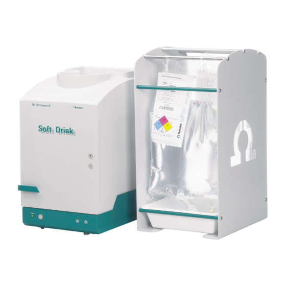
1.1 Instrument description 1 Introduction Instrument description The 761 SD Compact IC is a version of the time-proven 761 Compact IC which has been developed specifically for soft drink analysis. The 761 SD Compact IC is designed for determining phosphoric acid and its intermediate products in soft drinks but also continues to offer all functionalities of the original version. - Page 10 Ready-to-use eluents in certified MPaks are supplied for soft drink analysis. The 761 SD Compact IC is operated by means of a PC connected to the RS232 interface. The 761 SD Compact IC can be controlled by the «IC Net» software or by the “master” «IC Cap» software.
-
Page 11: Parts And Controls
Parts and controls In this section you will find the numbers and designations of the parts and controls of the 761 SD Compact IC. The numbering applies throughout the instructions for use, i.e. bold numbers in the text (e.g. ) refer to the parts and controls illustrated here. -
Page 12: Rear View
21 RS232 interface to secure the pump head when the in- PC connection strument is transported 14 Mains switch to switch instrument on and off: I = ON 0 = OFF 761 SD Compact IC / Instructions for Use 8.761.1043... -
Page 13: Connection Schematic
1.2 Parts and controls 1.2.3 Connection schematic Figure 3: Connection schematic for 761 SD Compact IC Aspirating tubing 27 Connection capillary for sample PEEK capillary 6.1831.010 for deaerating, 22 MPak cabinet length L = 15 cm for suspending eluent and regener-... - Page 14 PEEK capillary tubing (see Instructions for Use 766 IC Sam- ple Processor) installed on the 766 IC Sample Processor. See Section 2.9. for installation of the 766 IC Sample Processor. 761 SD Compact IC / Instructions for Use 8.761.1043...
-
Page 15: Information On The Instructions For Use
1.3.1 Organisation These Instructions for Use 8.761.1043 for the 761 SD Compact IC provide a comprehensive overview of installation, startup procedure, operation, fault rectification and technical specifications of this instru- ment. The Instructions for Use are organised as follows:... -
Page 16: Notation And Pictograms
Caution This symbol marks important in- formation. First read the associated directions before you continue. Comment This symbol marks additional in- formation and tips. 761 SD Compact IC / Instructions for Use 8.761.1043... -
Page 17: Safety Notes
Safety notes 1.4.1 Electrical safety While electrical safety in the handling of the 761 SD Compact IC is as- sured in the context of the specifications IEC/EN 61010-1 (prot. class 1, degree of protection IP20), the following points should be noted: •... -
Page 18: Installation
Connection to 766 IC Sample Processor Processor sect. 2.10 Replace rear panel Mains connection sect. 2.11 sect. 2.12 Connecting PC Installing software sect. 2.12.2 Deaerating/Rinsing sect. 2.13 / 2.14 Install guard and column sect. 2.15 761 SD Compact IC / Instructions for Use 8.761.1043... -
Page 19: Setting Up The Instrument
Setting up the instrument 2.2.1 Packaging The 761 SD Compact IC is supplied together with the separately packed accessories in special packagings containing shock-absorbing foam linings designed to provide excellent protection. The instrument itself is packed in an evacuated polyethylene bag to prevent the ingress of dust. -
Page 20: Description Of The Connections
Slide the end of the capillary fully into the corresponding connector (in order to avoid dead volume). Tighten the pressure screw Firmly tighten the pressure screw (50, 51 or 52) by hand (do not use tools). 761 SD Compact IC / Instructions for Use 8.761.1043... -
Page 21: Connection Between Capillaries/Tubing
Pressure screw 6.2744.010 54 PEEK coupling 6.2744.040 Pressure screw 6.2744.070 for IC pump 55 PEEK coupling 4.455.4500 coupling for "tubing connection to the MPak" Pressure screw 4.422.4510 for tubing connection 23 to MPak 761 SD Compact IC / Instructions for Use 8.761.1043... -
Page 22: Filter Unit Peek
For the connection of the filter unit, please note the flow direction ar- row printed on the housing. Figure 6: Connecting the filter unit PEEK Pressure screw 6.2744.010 Capillary PEEK capillary 6.1831.010 or PTFE- microcapillary 6.1803.030 56 Filter unit PEEK 6.2821.120 761 SD Compact IC / Instructions for Use 8.761.1043... -
Page 23: Connection Of The Detector Block
761 SD Compact IC. Since other connections need to be routed through the rear openings of the 761 SD Compact IC later on, you should not fit the rear panel back on until the end of the installation procedure (see Section 2.10). -
Page 24: Installation Of The Mpak Cabinet And Connection Of The Drain Tubes
Position it next to the 761 SD Compact IC and suspend the eluent and regenerant MPaks from the crossbars. Since eluent and re- generant are supplied from the rear to the 761 SD Compact IC, the out- lets of the MPaks should point to the rear. -
Page 25: Installing The Eluent Path
Connect the tubing connection to the eluent MPak outlet • Connect the other end of the tubing connection 23 to the elu- ent MPak outlet (pierce the connection and turn it through 90° clockwise). 761 SD Compact IC / Instructions for Use 8.761.1043... -
Page 26: Connection High-Pressure Pump → Injection Valve
Proceed as follows: Position the pulsation dampener Place the pulsation dampener 30 6.2620.150 in the inner com- partment of the 761 SD Compact IC on the bottom. Remove the PEEK coupling Remove the PEEK coupling 54 located between connection capillary 29 and 31. -
Page 27: Connection Injection Valve → Suppressor
Fit the filter unit PEEK Connect the "outlet capillary from detector block" 41 via the filter unit PEEK 54 (see Section 2.3.3) to the "suppressor inlet capil- lary for eluent ("H2O")" 42. 761 SD Compact IC / Instructions for Use 8.761.1043... -
Page 28: Connection Suppressor → Waste
Connection suppressor → waste 2.6.7 Route the "suppressor outlet capillary for eluent ("Waste")" 44 at the rear out of the 761 SD Compact IC into a waste container. Installing the regenerant path The regenerant (100 mmol/L H ) is aspirated with the peristaltic pump from the regenerant MPak and forced into the suppressor via the filter unit PEEK. -
Page 29: Connection Regenerant-Mpak → Pump Tubing → Suppressor → Waste
6.2744.010 (see also Section 2.3.3). Connection Suppressor - Waste • Route the "suppressor outlet capillary for regenerant ("Waste")" 46 at the rear out of the 761 SD Compact IC into a waste container. 761 SD Compact IC / Instructions for Use 8.761.1043... -
Page 30: Figure 9: Flow Schematic Regenerant Flow
Suppressor outlet capillary for re- generant ("Waste") Coupling 6.2744.110 PTFE capillary, permanently attached to the suppressor; leads in to the Pump tubing 6.1826.110 for H waste, labelled "Waste" Pressure screw 6.2744.010 761 SD Compact IC / Instructions for Use 8.761.1043... -
Page 31: Installing The Sample Path
Engage it at the left first and then push the right-hand side down until the snap-action lever 59 engages. Ensure that the pump tub- ing is not kinked when doing this. 761 SD Compact IC / Instructions for Use 8.761.1043... -
Page 32: Connection Sample Vessel → Pump Tubing → Injection Valve → Waste
50 from the injection valve (it is fitted there only for de- livery purposes) and screw it firmly onto the PEEK coupling 63 on the left-hand end of the pump tubing (flow inlet) (see Figure 11). 761 SD Compact IC / Instructions for Use 8.761.1043... -
Page 33: Figure 11: Flow Schematic Sample Stream
• Connect the supplied PTFE capillary 6.1803.030 with a pres- sure screw 50 6.2744.010 to the outlet of the injection valve. • Route the other end at the rear out of the 761 SD Compact IC into the waste container. Wait until after the rear panel has been fitted to cut it to size (see Section 2.10). -
Page 34: Connecting The 766 Ic Sample Processor
761 SD Compact IC. Sample changing and filling of the sample loop are each started by a signal output on the 761 SD Compact IC (761 SD Compact IC as "mas- ter"). -
Page 35: Fitting The Rear Panel
• Regenerant MPak • Detector connection cable • Input "Detector Block" Then fit the rear panel, fit the upper 2 knurled screws 11 and firmly screw all 4 knurled screws 11 tight. 761 SD Compact IC / Instructions for Use 8.761.1043... -
Page 36: Mains Connections
2.11.1 Setting the mains voltage Before switching on the 761 SD Compact IC for the first time, check that the mains voltage set on the instrument (see Figure 13) matches the lo- cal mains voltage. If this is not the case, you must reset the mains volt-... -
Page 37: Fuses
2.11.4 Switching the instruments on/off The 761 SD Compact IC is switched on and off using the mains switch 14. When the instrument is switched on, the mains pilot lamp 7 lights. 761 SD Compact IC / Instructions for Use 8.761.1043... -
Page 38: Connection To The Pc
Always switch off the 761 SD Compact IC and PC before you connect the two instruments with cable 6.2134.100. Connect the RS 232 interface 21 on the 761 SD Compact IC to the se- rial COM1 port of the PC using the connecting cable 6.2134.100 (9- pin/9-pin). -
Page 39: Basic Settings "Ic Net
Administrator ac- cess rights is created. You are advised to create the other users straight after installation. See Software Instructions for Use «IC Net 2.3», Section 3.2 for creating us- ers. 761 SD Compact IC / Instructions for Use 8.761.1043... - Page 40 Enter the cell constant • Enter the cell constant printed on detector block 1.732.0420 in field Cell constant • Click on to save the settings and close the window. <OK> 761 SD Compact IC / Instructions for Use 8.761.1043...
-
Page 41: Basic Settings "Ic Cap
Select the Miscellaneous tab in the window and CONFIGURATION click on the <Store Configuration> button. Save the configuration under a separate name. Close the software again (see Administrator Manual «IC Cap 2.0» Sec- tion 3.2). 761 SD Compact IC / Instructions for Use 8.761.1043... -
Page 42: Deaerating The Pump And Rinsing The Pulsation Dampener
• Open the rotary knob on the purge valve 26 by approx. ½ a turn counter-clockwise. • Remove the plastic stopper from the connection 6 on the front panel of the 761 SD Compact IC (see Figure 1). • Push the syringe 6.2816.020 (without needle) fully into the connection 6. -
Page 43: Rinsing The Pulsation Dampener
The isopropanol should not be rinsed through the suppressor and the detector. Consequently, the column connection capillary (which is currently connected to the suppressor via the PEEK coupling) must be detached from the PEEK coupling and routed into a beaker. 761 SD Compact IC / Instructions for Use 8.761.1043... - Page 44 • Take the end of the column connection capillary 33 out of the beaker and screw it back onto the PEEK coupling 54 (as a transition to the suppressor) with a pressure screw 50. 761 SD Compact IC / Instructions for Use 8.761.1043...
-
Page 45: Rinsing Before Fitting The Column
• Push the pressure lever 58 up on both tubing cartridges 57 until regeneration and rinsing solution is aspirated. • Then push the pressure lever 58 one detent position upwards to achieve an optimum pressure. 761 SD Compact IC / Instructions for Use 8.761.1043... - Page 46 Check for leaks • Check all capillaries and tubing and their connections in the 761 SD Compact IC for escaping fluid. If fluid is escaping at any point, the corresponding pressure screw must be tight- ened more firmly or exchanged.
-
Page 47: Precolumn And Separating Column
10 minutes with eluent. <On>, • Switch the high-pressure pump back off again by clicking on <Off> Next connect the Metrosep A Supp 1 HS separating column 36, see Section 2.15.2. 761 SD Compact IC / Instructions for Use 8.761.1043... -
Page 48: Metrosep A Supp 1 Hs Separating Column
36. Fix the separating column in position • Insert a column holder (6.2027.040) 67 into the mounting rails 66 and secure the separating column 36 in the column hol- der. 761 SD Compact IC / Instructions for Use 8.761.1043... -
Page 49: Figure 14: Connection Of Precolumn And Separating Column
66 Mounting rail for column holder 67 Connector PEEK connection between precolumn and separating column 67 Column holder 6.2027.040 Metrosep A Supp 1 HS separating column IC separating column 761 SD Compact IC / Instructions for Use 8.761.1043... -
Page 50: Attaching Tubing To Side Panels
Y.107.0150. The same applies to the two suppressor outlet capil- laries 44 and 46 and to the connection capillaries 48 which all lead into a waste container. 761 SD Compact IC / Instructions for Use 8.761.1043... -
Page 51: Ic Net
3.1 «IC Net» – User interface for the 761 SD Compact IC 3 «IC Net» The 761 SD Compact IC can be operated via «IC Net» or «IC Cap» (see Section 4). System and method settings can be modified only with «IC Net». -
Page 52: Opening A Method
METHOD SETUP Chromatogram directory: If you’ve installed the software in the default destination folder C:\Metrohm\SD Analyzer, this path will be correct for the supplied methods. You must otherwise adapt it. 3.1.4 Connect a system The selected system must be linked to the workplace for controlling the instrument and starting determination processes. -
Page 53: Instrument Icon
"INJECT" position position The instrument icon for the 761 SD Compact IC is one of the three ele- ments in the System window. If the system is linked (see Section 3.1.4), the icon is provided with two buttons for manual operation of the injec- tion valve: Switch over the injection valve to position "INJECT". - Page 54 <Step> The time since the last advance is displayed in the field next to <Step> High-pressure pump IC pump Switching on the pump drive. <On> Switching off the pump drive. <Off> 761 SD Compact IC / Instructions for Use 8.761.1043...
- Page 55 3.1 «IC Net» – User interface for the 761 SD Compact IC Peristaltic pump Peristaltic pump Switching on the pump drive. <On> Switching off the pump drive. <Off> System startup values. These parameters are System startup values set on the 761 SD Compact IC when linking the...
- Page 56 0.0 ... 25.0 MPa Set maximum pressure limit for the high-pressure pump to the desired value. Pmin 0.0 ... 25.0 MPa Set minimum pressure limit for the high-pressure pump to the desired value. 761 SD Compact IC / Instructions for Use 8.761.1043...
- Page 57 3.1 «IC Net» – User interface for the 761 SD Compact IC Remote 0, 1, *, p Set remote output lines 1...8 to the desired values. For entry of the first value, enter . For entry of the other values, move the cursor in front of...
-
Page 58: Hardware Settings
Hardware Outputs Alarm stops Hardware tab in the window for the hardware settings contains gen- Hardware erally valid settings which are set automatically when the instrument is switched on. 761 SD Compact IC / Instructions for Use 8.761.1043... - Page 59 3.1 «IC Net» – User interface for the 761 SD Compact IC Remote lines after power on The output lines 1… 8 are set to the val- ues defined here after switching on the instrument or after an emergency stop...
- Page 60 Leak in the inner compartment. Alarm leak detector Sets the output lines 1…8. Remote line Selection: (line off, inactive, open) (line on, active, 0 V) (output of a pulse) (do not change state) 761 SD Compact IC / Instructions for Use 8.761.1043...
- Page 61 Alarm stops for which the 761 SD Compact IC is stopped immediately. At an alarm stop, high-pressure pump and peristaltic pump are stopped immedi- ately, the running determination and the active sample queue are also stopped.
-
Page 62: Systems Supplied
30 minutes. System window System parameters Control tab Same settings as in the example with the system in Section manual.smt 3.1.6. Program tab Time program of the system. startup.smt 761 SD Compact IC / Instructions for Use 8.761.1043... -
Page 63: System "Manual.smt
Section manual.smt 3.1.6. Links tab Same settings as in the example with system in Section manual.smt 3.1.6. The 761 SD Compact IC should always be attached to COM1. Linked method Method is linked to system SD_startup.mtw startup.smt Most important settings: •... -
Page 64: System "Auto.smt
766 IC Sample Processor using the «IC Net» software can be found in the Software Instructions for Use «IC Net 2.3», Section 6.23, and in the Instructions for Use for the 766 IC Sample Processor. 761 SD Compact IC / Instructions for Use 8.761.1043... - Page 65 3.2 Systems supplied Manual tab - Manual subwindow For manual control of the 766 IC Sample Processor. Manual tab - Current State subwindow Status display of the 766 IC Sample Processor. 761 SD Compact IC / Instructions for Use 8.761.1043...
- Page 66 3 «IC Net» Program tab Time program of the 766 IC Sample Processor. Configuration tab – Rack subwindow 761 SD Compact IC / Instructions for Use 8.761.1043...
- Page 67 3.2 Systems supplied Configuration tab - Vial positions subwindow Configuration tab - Needle positions subwindow 761 SD Compact IC / Instructions for Use 8.761.1043...
- Page 68 3 «IC Net» Configuration tab - Control subwindow Configuration tab - Scan subwindow 761 SD Compact IC / Instructions for Use 8.761.1043...
-
Page 69: System "Shutdown.smt
7 minutes. Always inject water as the last sample and thus rinse the tubing con- nections with water in order to avoid damage to the instrument. 761 SD Compact IC / Instructions for Use 8.761.1043... - Page 70 Same settings as in the example with system in Section manual.smt 3.1.6. Links tab Same settings as in the example with system in Section manual.smt 3.1.6. The 761 SD Compact IC should always be attached to COM1. 761 SD Compact IC / Instructions for Use 8.761.1043...
- Page 71 Export tab of the METHOD IC Cap window. SETUP • "7 " should be entered for on the General tab of the Duration window. METHOD SETUP 761 SD Compact IC / Instructions for Use 8.761.1043...
-
Page 72: Ic Cap
4 «IC Cap» 4 «IC Cap» The 761 SD Compact IC can be operated via «IC Net» (see Section 3) or «IC Cap». System and method settings can be modified only with «IC Net». Using «IC Cap» is recommended for day-to-day operation. «IC Cap»... - Page 73 (using the buttons). The mode of representation of the sample parameters depends on whether is activated Manual Queue in the configuration (see Section 4.2). 761 SD Compact IC / Instructions for Use 8.761.1043...
-
Page 74: Ic Cap" - Configuration
SD Compact IC using «IC Cap». If you answered the prompt "Do you work with 766 IC Sample Processor?” (see Section 2.12.2) with <No> during the installation process, configuration is loaded auto- manual.cfg matically. Otherwise, you must load it subsequently (see Section 4.2.1). 761 SD Compact IC / Instructions for Use 8.761.1043... - Page 75 4.2 «IC Cap» - Configuration Settings of configuration "manual.cfg" General tab defined after installation (see Section 2.12.4) are listed in the Users User List Items tab 761 SD Compact IC / Instructions for Use 8.761.1043...
- Page 76 (see Section 4.2.3). Results tab These settings define the appearance of the Results frame. You can define the system which contains the corresponding ion names under System File for Ion Names 761 SD Compact IC / Instructions for Use 8.761.1043...
- Page 77 4.2 «IC Cap» - Configuration Limits tab With , there is only a warning entered in the report. None Action PreRun tab 761 SD Compact IC / Instructions for Use 8.761.1043...
- Page 78 The system does not start until after this con- firmation. Miscellaneous tab must be longer than 30 minutes. Otherwise there will Report Timeout be a timeout with system startup.smt 761 SD Compact IC / Instructions for Use 8.761.1043...
- Page 79 4.2 «IC Cap» - Configuration Main page with configuration "manual.cfg" 761 SD Compact IC / Instructions for Use 8.761.1043...
-
Page 80: Configuration "Auto.cfg
General tab Queue is activated in configuration . The "Queue" is a string of auto.cfg measurements. The "Queue" is shown in the main window and is proc- essed there (see Section 4.1.2). 761 SD Compact IC / Instructions for Use 8.761.1043... - Page 81 Items (as in the screenshot example); the path to the system file must now be specified correctly in the field . This path defines Directory the list box for system in the main window. 761 SD Compact IC / Instructions for Use 8.761.1043...
- Page 82 "Queue" with system shutdown.smt Results tab These settings define the appearance of the Results frame. You can define the system which contains the corresponding ion names under System File for Ion Names 761 SD Compact IC / Instructions for Use 8.761.1043...
- Page 83 4.2 «IC Cap» - Configuration Limits tab With , there is only a warning entered in the report. None Action PreRun tab No prompts which would interrupt the sequence should be defined. 761 SD Compact IC / Instructions for Use 8.761.1043...
- Page 84 4 «IC Cap» Miscellaneous tab must be longer than 30 minutes. Otherwise, there Report Timeout will be a timeout with system startup.smt Main page with configuration "auto.cfg" 761 SD Compact IC / Instructions for Use 8.761.1043...
-
Page 85: Operation
⇒ Switch on the PC. Switch on the 761 SD Compact IC ⇒ Switch the 761 SD Compact IC on with the mains switch 14 on the rear panel of the instrument. The pilot lamp 7 lights af- ter the instrument has been switched on. - Page 86 (6.1608.080) filled with ultra-pure water after each sample (or after an MCAL standard). Switch to system manual.smt and link it ⇒ Switch (see Software Instructions for Use «IC Net 2.3», Section 4.2) to system (see Section 3.2.2). manual.smt 761 SD Compact IC / Instructions for Use 8.761.1043...
- Page 87 ⇒ Detailed information on calibration can be found in the Soft- ware Instructions for Use «IC Net 2.3», Section 7.5. 761 SD Compact IC / Instructions for Use 8.761.1043...
- Page 88 This rinsing operation should be performed with system shutdown.smt (see Section 3.2.4). Switch to system shutdown.smt and link it ⇒ Switch (see Software Instructions for Use «IC Net 2.3», Section 4.2) to system (see Section 3.2.2). shutdown.smt 761 SD Compact IC / Instructions for Use 8.761.1043...
-
Page 89: Control With "Ic Cap" (Manual Operation)
⇒ Start the system by clicking on the green <Start> button and allow it run through to the end (30 minutes). Clicking on the <Chrom> button displays the win- CHROMATOGRAM dow. ⇒ The baseline should be stable at the end. 761 SD Compact IC / Instructions for Use 8.761.1043... - Page 90 MCAL QC check standard with 545 mg/L H plus basic content of nitrate and sulfate at the end of the series of cali- bration measurements. Choose type “Sample” in item for this measurement. Type 761 SD Compact IC / Instructions for Use 8.761.1043...
- Page 91 (answer should be yes!) water as last sample? and allow the determination to run through to the end (7.10 minutes). High-pressure pump and peristaltic pump are switched off automatically at the end. 761 SD Compact IC / Instructions for Use 8.761.1043...
-
Page 92: Operation With Automated Sample Change
⇒ Switch on the PC Switch on the 761 SD Compact IC ⇒ Switch on the 761 SD Compact IC with the mains switch 14 on the instrument rear panel. The pilot lamp 7 lights after switching on the instrument. - Page 93 SYSTEMS / System / Sample Queue... 5.2.1.3 Starting the sample table Start the open sample table by clicking on <Start> (see Software In- structions for Use «IC Net 2.3», Section 9.2.2) 761 SD Compact IC / Instructions for Use 8.761.1043...
-
Page 94: Control With "Ic Cap" (Automated Operation)
Section 2.3). First perform a conditioning step with system . Then perform the calibration measurements and the startup.smt sample determinations with the system . Assign the number auto.smt rack positions have selected. Vial 761 SD Compact IC / Instructions for Use 8.761.1043... - Page 95 5.2.2.3 Starting the sample table The sample table (Queue) is started with the green <Start> button at the top right (see Administrator Manual «IC Cap 2.0», Section 2.1). 761 SD Compact IC / Instructions for Use 8.761.1043...
-
Page 96: Notes - Maintenance - Faults
It serves to reduce disturbing pulsations in the case of highly sensitive measurements and also offers protection against pressure shocks act- ing on the column material caused by injection (installation, see Section 2.15). 761 SD Compact IC / Instructions for Use 8.761.1043... -
Page 97: Eluents
(see Section 2.3.3). Operation The Metrohm Suppressor Module MSM consists of a total of 3 sup- pressor units which are in turn used for suppression, regenerated with sulphuric acid and rinsed with back-flowing eluent. In order to record every new chromatogram under comparable conditions, work is nor- mally carried out with freshly regenerated suppressor. -
Page 98: Connections
(Section 6.2.6), cleaned (Section 6.2.7) or exchanged (Section 6.2.8). 6.1.6 Connections All connections between injector, column and detector must be as short as possible, have a low dead volume and must be absolutely tight. 761 SD Compact IC / Instructions for Use 8.761.1043... -
Page 99: Maintenance And Servicing
Section 1.4. Maintenance by Metrohm service Maintenance of the 761 SD Compact IC is best done as part of an an- nual service performed by specialists from the Metrohm company. If work is frequently performed with caustic and corrosive chemicals, it may be necessary to shorten the interval between servicing. -
Page 100: Changing Separating Columns
Proceed as follows for cleaning contaminated valves and/or replacement of parts subject to wear such as pistons, piston seals and valves: 761 SD Compact IC / Instructions for Use 8.761.1043... - Page 101 The tool must be screwed into the seal 76 which can then be pulled out (see Figure 16A). When the special tool is screwed into the piston seal , the latter is destroyed completely! 761 SD Compact IC / Instructions for Use 8.761.1043...
-
Page 102: Figure 15: Components Of The Pump Head
6 Notes – Maintenance – Faults 73 74 75 76 Figure 15: Components of the pump head Figure 16: Replacement of the piston seal 761 SD Compact IC / Instructions for Use 8.761.1043... - Page 103 24 and use the tool 80 to press the seal into the pump head recess (see Figure 16C). The seal surface in the pump head may not be damaged (avoid contact with tool)! 761 SD Compact IC / Instructions for Use 8.761.1043...
- Page 104 Tighten the screws when doing this with the Allen key 6.2621.030. • Screw the connection capillary 25 back onto the pump head • Connect the PEEK capillary 55 back onto the aspirating capil- lary on the pump head 24. 761 SD Compact IC / Instructions for Use 8.761.1043...
-
Page 105: Figure 17: Components Of Inlet Valve 77 And Outlet Valve 78
Consequently, the deepest bore must be assigned to the longest pin. If this is not the case, the pump will not function correctly. 761 SD Compact IC / Instructions for Use 8.761.1043... -
Page 106: Regeneration Of The Suppressor Module
/ acetone ≥ 20 % Connect the suppressor to the IC system • Reconnect the suppressor to the IC system. If capacity prob- lems persist, replace the suppressor rotor (see Section 6.2.8). 761 SD Compact IC / Instructions for Use 8.761.1043... - Page 107 Connect the suppressor to the IC system • Reconnect the suppressor inlet capillaries 45 and 42 nor- mally again (see Figure 3). • If the pressure problems persist, replace the suppressor rotor (see Section 6.2.8). 761 SD Compact IC / Instructions for Use 8.761.1043...
-
Page 108: Cleaning The Suppressor
90 (order number 6.2832.010). 4 Clean the suppressor rotor • Clean the sealing surface of the suppressor rotor 91 using a lint-free cloth and ethanol. 761 SD Compact IC / Instructions for Use 8.761.1043... -
Page 109: Figure 18: Assembling The Suppressor
Connect and condition the suppressor • Reconnect the suppressor to the IC system. • Before switching the suppressor to the next position, rinse all three suppressor units with solution for 5 minutes. 761 SD Compact IC / Instructions for Use 8.761.1043... -
Page 110: Replacing The Suppressor
• Screw the nut 89 onto the thread of the suppressor holder 92 by hand (do not use tools). 761 SD Compact IC / Instructions for Use 8.761.1043... -
Page 111: Replacing The Pump Tubing
• Press the contact pressure lever 58 upwards until the solution just starts to be aspirated. Then press the contact pressure lever upwards until it clicks once more to obtain optimal con- tact pressure. • Switch off the peristaltic pump. 761 SD Compact IC / Instructions for Use 8.761.1043... -
Page 112: Faults And Malfunctions
Software Instructions for Use «IC Net 2.3» Section 4.5. 6.3.2 Malfunctions and their rectification If difficulties appear with The 761 SD Compact IC during analyses, their causes are best investigated in The order separating column → high- pressure pump → eluent → connections. Several of The malfunc- tions which may appear are listed in The following table with details of possible causes and countermeasures. - Page 113 • Replace the filter filter in the filter unit 6.2821.130 (see Section PEEK 6.2821.120 2.3.3) • Counter-pressure at • Clean or replace the sup- suppressor module too pressor (see Sections … high 6.2.6 6.2.8) 761 SD Compact IC / Instructions for Use 8.761.1043...
-
Page 114: Diagnostic Tests / Validation / Glp
Under the title «Application Bulletin No. 277 – Validation of Metrohm ion chromatographs» an example of such a standard op- erating procedure is available from Metrohm; it can be adapted and used with the 761 SD Compact IC. Further information on the subjects of QA, GLP and validation can also be found in the brochure «Quality management with Metrohm»,... -
Page 115: Appendix
7.1 Technical data 7 Appendix Technical data Unless otherwise specified, the published data com- prises typical values for the 761 SD Compact IC at an ambient temperature of 25 °C. 7.1.1 Conductivity measurement 0…1000 µS/cm (resolution: 0.56 nS/cm) Measurement range 1 0…250 µS/cm (resolution: 0.14 nS/cm) -
Page 116: Injection Valve
Minimum pressure limit adjustable between 0.1 ... 25.0 MPa (1...250 bar), inactive at 0 MPa Response time: 5 pump cycles Pump head 40 µL Pump head volumes Main piston: 20 µL Priming piston: 761 SD Compact IC / Instructions for Use 8.761.1043... -
Page 117: Peristaltic Pump
Resistance < 1 MΩ (for deion. water) 7.1.8 RS232 interface Connector Dsub 9 pin (male) Function TxD and RxD signal for connection with software handshake Default settings 9600 baud, 8 bit, 1 stop bit, no parity, XON/XOFF 761 SD Compact IC / Instructions for Use 8.761.1043... -
Page 118: Remote Interface
230 V: 220...240 V ± 10 % Frequency 50...60 Hz Power consumption 100 VA Fuse 5 mm dia., 20 mm length 100…120 V: 1.0 A (slow-blow) 220…240 V: 0.5 A (slow-blow) 761 SD Compact IC / Instructions for Use 8.761.1043... -
Page 119: Safety Specifications
Material of base Steel, enamelled Width 259 mm Height 446 mm Depth 355 mm Weight 761 SD Compact IC 14.7 kg (without accessories) 766 IC Sample Processor 12.3 kg (without accessories) 761 SD Compact IC / Instructions for Use 8.761.1043... -
Page 120: Standard Equipment
All dimensions are given in mm. The 761 Compact IC is available in two versions: • 2.761.0420 761 SD Compact IC • 2.761.0520 761 SD Compact IC with 766 IC Sample Processor These instruments include the following parts: Quant. Order No. Description 1.761.0420... - Page 121 For aspiration of solutions from open sample tubes 6.1837.000 Tubing connection to MPak Connection to Eluent- and Regenerant MPak, with PEEK coupling (55) 4.455.4500 Length = 1.5 m 6.2027.030 Column holder Diameter d = 8.5 mm 761 SD Compact IC / Instructions for Use 8.761.1043...
- Page 122 M3.5 6.2617.010 Special tool For removing/fitting the piston seal of the pump head. 6.2620.150 Pulsation dampener MF Metal-free pulsation dam- pener to reduce pulsation and prolong the life of separating columns. 761 SD Compact IC / Instructions for Use 8.761.1043...
- Page 123 (only suitable for aqueous eluents) 6.2743.050 PP Sample tube (11 mL) For 6.2041.430 sample rack. set of 2000 6.2743.070 PP Cap For sealing the 6.2743.050 sample tubes. set of 2000 761 SD Compact IC / Instructions for Use 8.761.1043...
- Page 124 PP, volume = 10 mL for manual filling of the sam- ple loop Filter unit PEEK 2 µm 6.2821.120 To avoid contamination due to abrasive particles of piston seals. Spare part: 6.2821.130 Filter 761 SD Compact IC / Instructions for Use 8.761.1043...
- Page 125 PC-program «IC Net 2.3» 8.110.8293 Compliance white paper (English) for PC-program «IC Net 2.3» 8.110.8313 Administrator manual (English) for PC-program «IC Cap 2.0» 8.110.8319 User manual (English) for PC-program «IC Cap 2.0» 761 SD Compact IC / Instructions for Use 8.761.1043...
-
Page 126: Optional Accessories
6.5328.000 SD Spare Part Set A specially selected spare parts set is available under order number 6.5328.000 for the 761 SD Compact IC. All parts listed can also be or- dered individually, quoting the corresponding order number. The 6.5328.000 SD Spare Part Set includes the following parts: Quant. - Page 127 Filter for Filter Unit PEEK 2 µm Spare filter for filter unit PEEK 6.2821.120. set of 10 6.2824.070 Zircon piston Spare part for 6.2824.040 and 6.2824.100 ∅3 pump heads 65.5 6.5904.030 Rotor to injection valve 761 SD Compact IC / Instructions for Use 8.761.1043...
-
Page 128: Other Optional Accessories
Spare part for 6.2824.100 Pump head 6.2824.090 Inlet valve (metal-free) ∅8 Spare part for 6.2824.100 Pump head 6.2832.000 Suppressor rotor Replacement cartridge for Metrohm suppressor module 6.2832.420 Connection to Suppressor-Rotor With in- and outlet tubing 761 SD Compact IC / Instructions for Use 8.761.1043... -
Page 129: Warranty And Conformity
Metrohm from any liability to pay compensation. If any instruments and parts have to be returned, the original packaging should be used if at all possible. -
Page 130: Declaration Of Conformity
EN 61010-1 Safety requirements for electrical equipment for measurement, control and laboratory Metrohm Ltd. is holder of the SQS-certificate of the quality system ISO 9001 for quality assurance in design/development, production, installation and servicing. The system software, stored in Read Only Memories (ROMs) has been validated in connection with standard operating procedures in respect to functionality and performance. -
Page 131: Quality Management Principles
Metrohm Ltd. holds the ISO 9001 Certificate, registration number 10872-02, issued by SQS (Swiss Association for Quality and Management Systems). Internal and external au- dits are carried out periodically to assure that the standards defined by Metrohm’s QM Manual are maintained. -
Page 132: Index
Column holder Figure ...........6 Description of the connections ..12 Order designation....114 Connection capillary 47 Detachable rear panel 12 Column holder 66 Figure ........6, 25 Figure........... 4 Connection capillary 48 761 SD Compact IC / Instructions for Use 8.761.1043... - Page 133 System startup value ....47 Opening rear panel ....15 Front ..........3 Monography "Ion chromatography" Leak detector Full scale........46, 47 ............88 Technical data ......109 FullScale ........48 Mounting rail 66 Leakage ........104 761 SD Compact IC/ Instructions for Use 8.761.1043...
- Page 134 Figure .........13 Technical data ......110 Order designation....113 Pressure# Replacement of the piston seal ..PEEK pressure screw 4.422.4510.12 Measurement ......108 ..........89,94 Range ........108 Replacing the suppressor... 102 761 SD Compact IC / Instructions for Use 8.761.1043...
- Page 135 Zircon piston 6.2824.070 .....119 «IC Cap» ........83 („Waste“) 44 Zirconium piston 69 «IC Net»........80 Figure........... 6 Figure .........95 Shutdown hardware ...... 51 Suppressor outlet capillary for Sleeve 84 regenerant („Waste“) 46 Figure......... 97 761 SD Compact IC/ Instructions for Use 8.761.1043...
Need help?
Do you have a question about the 761 SD Compact IC and is the answer not in the manual?
Questions and answers