
Related Manuals for Camille Bauer SIRAX BT5200


Summary of Contents for Camille Bauer SIRAX BT5200
- Page 1 Operating Instructions SIRAX BT5200 Transducer for AC current Camille Bauer Metrawatt AG Aargauerstrasse 7 CH-5610 Wohlen/Switzerland Tel: +41 56 618 21 11 Fax: +41 56 618 21 21 info@cbmag.com www.camillebauer.com...
- Page 2 Necessary corrections will be included in subsequent version and are available via our webpage http://www.camillebauer. com. Feedback If you detect errors in this document or if there is necessary information missing, please inform us via e-mail to: customer-support@camillebauer.com PM 1000289 000 01 Device handbook SIRAX BT5200 2/32...
-
Page 3: Table Of Contents
9. Technical data …………………………………………………………………………………………………………… 25 10. Dimensional drawings ………………………………………………………………………………………………………… 28 11. Interface Definition Modbus RTU ……………………………………………………………………………………………… 29 11.1 Modbus functions …………………………………………………………………………………………………………… 29 11.2 Datatyp …………………………………………………………………………………………………………… 29 11.3 Modbus register …………………………………………………………………………………………………………… 30 PM 1000289 000 01 Device handbook SIRAX BT5200 3/32... -
Page 4: Introduction
1. Introduction 1.1 Purpose of this document This document describes the universal measurement device SIRAX BT5200. It is intended to be used by: Installation personnel and commissioning engineers • Service and maintenance personnel • Planners • Scope This handbook is valid for all hardware versions of the BT5200. Some of the functions described in this document are available only, if the neces- sary optional components are included in the device. -
Page 5: Device Overview
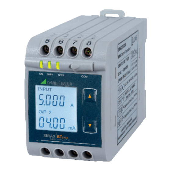
3. Device overview The SIRAX BT5200 is a top-hat rail mounted Transducer and used to measure and convert AC Current input into an proportional DC current or voltage output signal. Input Current and Output Voltage/Current is displayed on LCD and indicated by LED’s. -
Page 6: Electrical Connections
A marked and easily accessible current limiting switch has to be arranged in the vicinity of the device for turning off the power supply. Fusing should be 10 Amps or less and must be rated for the available voltage and fault current. PM 1000289 000 01 Device handbook SIRAX BT5200 6/32... -
Page 7: Connection Diagram
Before commissioning you have to check if the connection data of the device match the data of the plant. If so, you can start to put the device into operation by switching on the power supply and the measurement inputs. Label version PM 1000289 000 01 Device handbook SIRAX BT5200 7/32... -
Page 8: Operating The Device
O/P1 O/P2 O/P1 O/P2 SIRAX BT5200 can be configured and programmed at site for the following: CT Primary, CT Secondary (5A or 1A), Input parameters (i.e start, end and INPUT x012 INPUT elbow value of Input) and Output parameters (i.e as Voltage or as Current and start, end and elbow value of outputs). -
Page 9: Programming
3) Programming via optional RS485 (Modbus) communication port. 7.1 Programming via Front LCD & Two keys The following sections comprise step by step procedures for configuring the SIRAX BT5200 for individual user requirements. To access the set-UP screens, press and hold the “... -
Page 10: New/Change Password
Down” key will scroll the value of the third digit from 0 through to 9, the value will wrap from 9 round to 0. Pressing the “ Up” key will advance the operation to the next digit and set the third digit, in this case to “4” O/P1 O/P2 PM 1000289 000 01 Device handbook SIRAX BT5200 10/32... -
Page 11: Current Transformer Parameter Selection
Down” key will scroll the value of the second digit from 0 through to 9, the value will wrap from 9 round to 0. Pressing the “ Up” key will advance the operation to the next digit and set the second digit, in this case to “0”. O/P1 O/P2 PM 1000289 000 01 Device handbook SIRAX BT5200 11/32... -
Page 12: Current Transformer Secondary Value
5 round to 1. Pressing the “ Up” key to advance the operation to the “New / Changed CT Secondary value” and sets the fourth digit, in this case to “5”. O/P1 O/P2 PM 1000289 000 01 Device handbook SIRAX BT5200 12/32... -
Page 13: Communication Parameter Selection
9 round to 0. Pressing the “ Up” key will advance the operation to the “New / Changed Address value confirmed” and set the fourth digit, in this case to “6”. O/P1 O/P2 PM 1000289 000 01 Device handbook SIRAX BT5200 13/32... -
Page 14: Rs 485 Baud Rate
O/P1 O/P2 Pressing “ Down” key will be re-enter into Parity Edit mode. Pressing the “ Up” key will set the value and advance to the Output Type selection (section 7.1.4). PM 1000289 000 01 Device handbook SIRAX BT5200 14/32... -
Page 15: Output Type Selection
Down” key will re-enter into Output 2 type Edit mode. Pressing the “ Up” key will set the type and advance to the Input Parameter selection (section 7.1.5). O/P 2 O/P1 O/P2 INPUT O/P1 O/P2 INPUT PM 1000289 000 01 Device handbook SIRAX BT5200 15/32... -
Page 16: Input Parameter Selection
Down” key will re-enter to the “New / Change End value of Input edit” mode. INPUT x012 INPUT Pressing the “ Up” key will confirm New End value of Input and advance to the Start value of Input selecti- on (section 7.1.5.2). O/P 12 y012 PM 1000289 000 01 Device handbook SIRAX BT5200 16/32... -
Page 17: Start Value Of Input
INPUT Pressing the “ Up” key will confirm New Start value of Input and advance to the Elbow function selection (section 7.1.5.3). O/P 12 y012 O/P1 O/P2 INPUT PM 1000289 000 01 Device handbook SIRAX BT5200 17/32 O/P1 O/P2 INPUT... -
Page 18: Elbow Function Selection
9 round to 0 depending on set value of End value of Input. Pressing the “ Up” key will advance the operation to the next digit and set the third digit, in this case to “1”. O/P1 O/P2 INPUT PM 1000289 000 01 Device handbook SIRAX BT5200 18/32... -
Page 19: Output Parameter Selection
O/P 1 Pressing the “ Up” key will advance the operation to the next digit and set the first digit, in this case to “0”. O/P1 O/P2 PM 1000289 000 01 Device handbook SIRAX BT5200 19/32 O/P1 O/P2 O/P 1... -
Page 20: Elbow Value Of Output 1
2 round to 0 depending on the set End value of Output. O/P 1 Pressing the “ Up” key will advance the operation to the next digit and set the first digit, in this case to “1”. PM 1000289 000 01 Device handbook SIRAX BT5200 20/32 O/P1 O/P2... -
Page 21: Output 2 Parameter Selection
Up” key will set the present value as End value of the Output 2 and advance to the Start value of Output selection (section 7.1.6.2.2). O/P 2 O/P1 O/P2 O/P 2 PM 1000289 000 01 Device handbook SIRAX BT5200 21/32 O/P1 O/P2... -
Page 22: Start Value Of Output 2
Pressing the “ Up” key will confirm New Start value of the Output 2 and advance to the Elbow value of O/P 2 Output selection (section 7.1.6.2.3) or exit setup menu. PM 1000289 000 01 Device handbook SIRAX BT5200 22/32... -
Page 23: Elbow Value Of Output 2
Down” key will re-enter to the “New / Change Elbow value of the Output 2”. Pressing the “ Up” key will confirm New Elbow value of the Output 2 and exit setup menu. O/P 2 PM 1000289 000 01 Device handbook SIRAX BT5200 23/32... -
Page 24: Programming Via The Programming Connection And The Prkab5000 Programming Cable
Chapter 11. Schritt 2: Programming Program SIRAX BT5200 via the Modbus RTU interface and the CB-Configurator software. Please observe the detailed Modbus description in Chapter 11. To change the output from current to voltage, enter the value “1”. -
Page 25: Service, Maintenance And Disposal
Incorrect disposal can cause environ- mental risks. 8.5 Return All devices delivered to Camille Bauer Metrawatt AG shall be free of any hazardous contaminants (acids, lyes, solutions, etc.). Use original packaging or suitable transport packaging to return the device. Damage by returning Damages caused by improper returning, no warranties or guarantees can be given. -
Page 26: Technical Data
Bent characteristics: 1– Y1 – Y0 1– · or C=1 or C=1 X1 – X0 or C=1 1– 1– Output characteristics: 1) Example of setting with Linear characteristics: PM 1000289 000 01 Device handbook SIRAX BT5200 26/32 Y Y Y... - Page 27 490V, Output versus output versus each other versus outer surface. Installation Data: Material: Lexan 940 (polycarbonate), V-0 acc. to UL94, self-extinguishing, non-dripping, free of halogen Mounting position: Rail mounting / wall mounting Weight: Approx. 0.4kg PM 1000289 000 01 Device handbook SIRAX BT5200 27/32...
-
Page 28: Dimensional Drawings
106,5mm 11. Interface Definition Modbus RTU SIRAX BT5200 supports Modbus RTU protocol (RS485). The permissible address range for the BT5200 is between 1 and 247. Broadcast Mode (address 0) is not allowed. The maximum latency time of an BT5200 is 200ms i.e. this is the amount of time that can pass before the first response character is output. -
Page 29: Modbus Functions
The second register contains the bits 0 – 15 • 32-Bit Float (Real32) exponent mantissa sign 0x3C52 0xC75D Exponent: 120-127=-7 Mantisse=1.00111100010100101100011101011101=1.64670908451080325424989 Measuring value I = 1.64670908451080325424989 * 2 = 0.012864915 A PM 1000289 000 01 Device handbook SIRAX BT5200 29/32... -
Page 30: Modbus Register
– – 40035 Analog O/P 2 This address is used to set the Analog O/P2 as Voltage/Current. Voltage = 1 Current = 2 40037 – – – 40039 – – – PM 1000289 000 01 Device handbook SIRAX BT5200 30/32...
Need help?
Do you have a question about the SIRAX BT5200 and is the answer not in the manual?
Questions and answers