
Related Manuals for Camille Bauer SIRAX CH-5610


Summary of Contents for Camille Bauer SIRAX CH-5610
- Page 1 Operating Instructions SIRAX BT5100 Transducer for AC voltage Camille Bauer Metrawatt AG Aargauerstrasse 7 CH-5610 Wohlen/Switzerland Tel: +41 56 618 21 11 Fax: +41 56 618 21 21 info@cbmag.com www.camillebauer.com...
- Page 2 Legal information Warning notices In this document warning notices are used, which you have to observe to ensure personal safety and to prevent damage to property. Depending on the degree of danger the following symbols are used: If the warning notice is not followed death or severe personal injury will result. If the warning notice is not followed damage to property or severe personal injury may result.
-
Page 3: Table Of Contents
Table of content 1. Introduction ………………………………………………………………………………………………………… 4 1.1 Purpose of this document ……………………………………………………………………………………………… 4 1.2 Scope of supply ………………………………………………………………………………………………………… 4 1.3 Further documents ……………………………………………………………………………………………………… 4 2. Safety notes ………………………………………………………………………………………………………… 4 3. Device overview ………………………………………………………………………………………………………… 5 4. Mechanical mounting …………………………………………………………………………………………………… 5 4.1 Mounting …………………………………………………………………………………………………………... -
Page 4: Introduction
1. Introduction 1.1 Purpose of this document This document describes the universal measurement device SIRAX BT5100. It is intended to be used by: Installation personnel and commissioning engineers • Service and maintenance personnel • Planners • Scope This handbook is valid for all hardware versions of the BT5100. Some of the functions described in this document are available only, if the neces- sary optional components are included in the device. -
Page 5: Device Overview
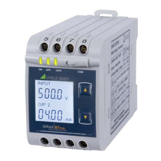
3. Device overview The SIRAX BT5100 is a top-hat rail mounted Transducer and used to measure and convert AC Voltage input into an proportional DC current or voltage output signal. Input Voltage and Output Voltage/Current is displayed on LCD and indicated by LED’s. 4. -
Page 6: Electrical Connections
5. Electrical connections Ensure under all circumstances that the leads are free of potential when connecting them! 5.1 General safety notes Please observe that the data on the type plate must be adhered to! The national provisions have to be observed in the installation and material selection of electric lines! Symbol Meaning Device may only be disposed of in a professional manner! -
Page 7: Connection Diagram
5.5 Connection Diagram Input U Connection Terminal details I/P ~ Measuring input I/P ~ Auxilliary power supply AUX ~ - O/P1 Measuring output - 1 O/P1 O/P2 Measuring output - 2 O/P2 – Modbus – A B G – Output-1 Output-2 RS485 5.6 Modbus interface RS485... -
Page 8: Operating The Device
6.1 Operating the device O/P1 O/P2 SIRAX BT5100 can be confi gured and programmed at site for the following: PT Primary, PT Secondary, Input parameters (i.e start, end and elbow value of Input) and Output parameters (i.e as Voltage or as Current and start, end and elbow value of outputs). -
Page 9: Programming
7. Programming Programming of transducer can be done in three ways: 1) Programming via Front LCD & two keys. 2) Programming via Programming port available at front of Transducers using optional PRKAB5000 adapter 3) Programming via optional RS485 (Modbus) communication port. 7.1 Programming via Front LCD &... -
Page 10: Password Verifi Cation
Password Set/Confi rmed O/P1 O/P2 Pressing “ Down” key will enter to the “New / change Password” entry stage.(section 7.1.1.2) Pressing the “ Up” key will advance to the Potential Transformer parameter selection(section 7.1.2). Password Incorrect. O/P1 O/P2 This screen is displayed when the unit has not accepted the Password entered. Pressing the "... -
Page 11: Potential Transformer Parameter Selection
Enter New / Change Password, third digit entered, prompting for fourth digit. (* denotes that digit will be O/P1 O/P2 fl ashing). Pressing the “ Down” key will scroll the value of the fourth digit from 0 through to 9, the value will wrap from 9 round to 0. -
Page 12: Potential Transformer Secondary Value
Enter New / Change PT Primary value, fi rst digit entered, prompting for second digit. O/P1 O/P2 (*Denotes that digit will be fl ashing). INPUT x012 Pressing the “ Down” key will scroll the value of the second digit from 0 through to 9, the value will wrap from 9 round to 0. -
Page 13: Communication Parameter Selection
New / Change PT Secondary value O/P1 O/P2 (*Denotes that digit will be fl ashing). INPUT x012 Pressing the “ Down” key will scroll the value of the Second digit from 0 through to 9, the value will wrap from 9 round to 0. O/P 12 y012 Pressing the “... -
Page 14: Rs 485 Baud Rate
New/changed Address value O/P1 O/P2 (*Denotes that digit will be fl ashing). Pressing the “ Down” key will scroll the value of the second digit from 0 through to 2, the value will wrap from 2 round to 0. Pressing the “ Up”... -
Page 15: Rs 485 Parity Selection
7.1.3.3 RS 485 Parity Selection: This screen allows the user to set Parity & number of stop bits of RS 485 port. Pressing the “ Down” key will enter the “Parity & stop bit edit” mode and scroll the value through O/P1 O/P2 odd: odd parity with one stop bit... -
Page 16: Input Parameter Selection
Output 2 Type confi rmation O/P1 O/P2 Pressing “ Down” key will re-enter into Output 2 type Edit mode. Pressing the “ Up” key will set the type and advance to the Input Parameter selection(section 7.1.5). O/P 2 7.1.5. Input parameter selection 7.1.5.1 End value of Input This screen allows the user to set the End value of Input. -
Page 17: Start Value Of Input
New/changed End value of Input confi rmed. O/P1 O/P2 Pressing the “ Down” key will re-enter to the “New / Change End value of Input edit” mode. INPUT x012 INPUT Pressing the “ Up” key will confi rm New End value of Input and advance to the Start value of Input selecti- on (section 7.1.5.2). - Page 18 7.1.5.3 Elbow Function selection This screen allows the user to enable or disable Elbow function of input. Pressing the “ Down” key will enter the “Selection of Elbow function of Input edit” mode and scroll the O/P1 O/P2 value between yes and no. INPUT YES : Elbow function is enabled.
-
Page 19: Output Parameter Selection
Enter New / Change Elbow value of the Input, third digit entered, prompting for fourth digit. (* denotes that O/P1 O/P2 digit will be fl ashing). INPUT x012 INPUT Pressing the “ Down” key will scroll the value of the fourth digit from 0 through to 9, the value will wrap from 9 round to 0 depending on set value of End value of Input. -
Page 20: Start Value Of Output 1
Enter New / Change End value of the Output 1, second digit entered, prompting for third digit. (*Denotes that O/P1 O/P2 digit will be fl ashing). Pressing the “ Down” key will scroll the value of the third digit from 0 through to 9, the value will wrap from 9 round to 0. -
Page 21: Elbow Value Of Output 1
Enter New / Change Start value of the Output 1, second digit entered, prompting for third digit. (*Denotes that O/P1 O/P2 digit will be fl ashing). Pressing the “ Down” key will scroll the value of the third digit from 0 through to 9, the value will wrap from 9 round to 0 depending on the set End value of Output. -
Page 22: Output 2 Parameter Selection
Enter New / Change Elbow value of the Output 1, fi rst digit entered, prompting for second digit. (*Denotes O/P1 O/P2 that digit will be fl ashing). Pressing the “ Down” key will scroll the value of the second digit from 0 through to 9, the value will wrap from 9 round to 0depending on the set End value of Output. - Page 23 New / Change End value of the Output 1 O/P1 O/P2 (*Denotes that digit will be fl ashing). Pressing the “ Down” key will scroll the value of the fi rst digit from 0 through to 1, the value will wrap from 1 round to 0.
- Page 24 7.1.6.2.2 Start value of output 2 This screen allows the user to set the Start value of Output 2 (considerd as DC Voltage). Start value of Output can be set up to 20% of set End value of Output. O/P1 O/P2 Pressing the “...
- Page 25 7.1.6.2.3 Elbow value of output 2 This screen appears only when Elbow function is enabled. This screen allows the user to set the Elbow value of Output 2 (considerd as DC Volta- ge). The Elbow value can be set any value between set Start value of Output and End value of Output. O/P1 O/P2 Pressing the “...
-
Page 26: Programming Via The Programming Connection And The Prkab5000 Programming Cable
7.2 Programming via the programming connection and the PRKAB5000 programming cable Follow the subsequent steps to program the SIRAX BT5100 transducer via the programming connection and the PRKAB5000 programming cable: Power supply Step 1: DIP switch setting The DIP switches should be confi gured for the desired measurement output as described in Chapter 7.4. -
Page 27: Calibration And New Adjustment
Incorrect disposal can cause environ- mental risks. 8.5 Return All devices delivered to Camille Bauer Metrawatt AG shall be free of any hazardous contaminants (acids, lyes, solutions, etc.). Use original packaging or suitable transport packaging to return the device. Damage by returning Damages caused by improper returning, no warranties or guarantees can be given. - Page 28 Accuracy (Acc. to EN 60688) Reference Value: Output end Value Y2 (Voltage or Current) Basic Accuracy: 0.2*C Factor C (The Highest value applies): Linear characteristics: Bent characteristics: Y1 – Y0 1– · or C=1 X1 – X0 or C=1 1– 1–...
- Page 29 Auxiliary supply voltage: Rated Value ±1% Auxiliary supply frequency: Rated Value ±1% Output Load: Rn = 7.5 V / Y2 ± 1% With DC current output signal. Rn = Y2 / 1 mA ± 1% With DC Voltage output signal. Additional Error: Temperature infl...
-
Page 30: Dimensional Drawings
10. Dimensional drawings 43,5mm 106,5mm 11. Interface Defi nition Modbus RTU SIRAX BT5100 supports Modbus RTU protocol (RS485). The permissible address range for the BT5100 is between 1 and 247. Broadcast Mode (address 0) is not allowed. The maximum latency time of an BT5100 is 200ms i.e. this is the amount of time that can pass before the fi rst response character is output. After sending any query through software (of the Master), it must allow 200ms of time to elapse before assuming that the BT5100 is not going to respond. -
Page 31: Datatyp
Example of set slave address to 2 Query: Device address Function code Start address Nr. of register Nr. of bytes Databytes 0...3 0x01 0x10 0x000E 0x0002 0x04 0x40000000 0x67E3 Response: Device address Function code Start address Nr. of register 0x01 0x10 0x000E 0x0002... -
Page 32: Modbus Register
11.3 Modbus Register Address Read/ Name Description (Register) Write 30001 Voltage Input voltage (RMS) 40001 – – – 40003 Mode selection This is used to select the Mode of operation. Normal mode = 1 Simulation mode = 2 40005 – –...
Need help?
Do you have a question about the SIRAX CH-5610 and is the answer not in the manual?
Questions and answers