Table of Contents

Related Manuals for Camille Bauer SIRAX BT5700


Summary of Contents for Camille Bauer SIRAX BT5700
- Page 1 Operating Instructions SIRAX BT5700 Programmable transducer for heavy current variables Camille Bauer Metrawatt AG Aargauerstrasse 7 CH-5610 Wohlen/Switzerland Tel: +41 56 618 21 11 Fax: +41 56 618 21 21 info@cbmag.com www.camillebauer.com...
- Page 2 Necessary corrections will be included in subsequent version and are available via our webpage http://www.camillebauer. com. Feedback If you detect errors in this document or if there is necessary information missing, please inform us via e-mail to: customer-support@camillebauer.com PM 1000284 000 01 Device handbook SIRAX BT5700 2/31...
-
Page 3: Table Of Contents
10.5 Return ………………………………………………………………………………………………………………… 23 11. Technical data ……………………………………………………………………………………………………………… 24 12. Dimensional drawings ……………………………………………………………………………………………………… 26 13. Interface Defi nition Modbus RTU …………………………………………………………………………………………… 27 13.1 Modbus functions ……………………………………………………………………………………………………… 27 13.2 Data types ……………………………………………………………………………………………………………… 27 PM 1000284 000 01 Device handbook SIRAX BT5700 3/31... -
Page 4: Introduction
1. Introduction 1.1 Purpose of this document This document describes the universal measurement device SIRAX BT5700. It is intended to be used by: Installation personnel and commissioning engineers • Service and maintenance personnel • Planners • Scope This handbook is valid for all hardware versions of the BT5700. Some of the functions described in this document are available only, if the neces- sary optional components are included in the device. -
Page 5: Device Overview
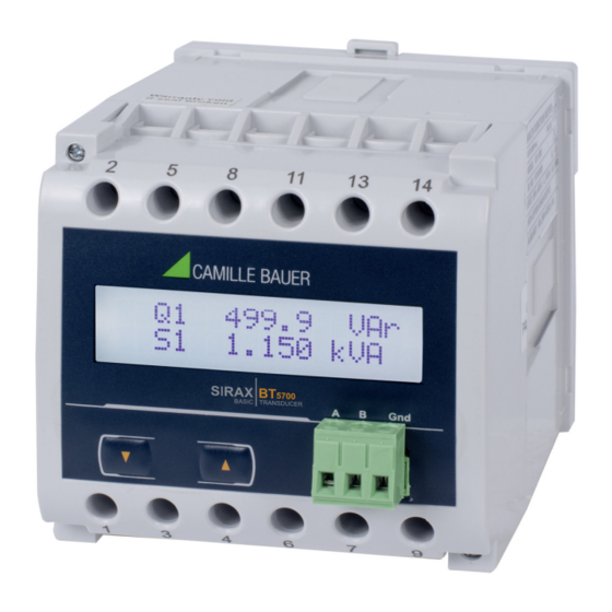
3.1 Brief description The universal measuring device SIRAX BT5700 is suited for fi xed mounting and the measurement of Voltage, current, frequency, power, energy (active / reactive / apparent), power factor, phase angle, etc in low voltage switchgear. The units are designed for unbalanced load network forms of 3-phase mains with 3- or 4-wire. -
Page 6: Mechanical Mounting
4. Mechanical mounting The SIRAX BT5700 is designed for panel mounting. Please ensure that the operating temperature limits are not exceeded when determining the place of mounting (place of measurement): –10 … +55° C 4.1 Mounting Dimensional drawing BT5700: See section 11 Any mounting position is possible. -
Page 7: Electrical Connections
Torque: 0.5 … 0.6Nm rsp. 4.42 … 5.31 lbf in Terminal A, B, G Single wire: ≤ 1,5mm or multiwire with end splices: 2 x 0,5mm Torque: max. 0.5 Nm rsp. 4.42 lbf in PM 1000284 000 01 Device handbook SIRAX BT5700 7/31... -
Page 8: Inputs
13 14 SUPPLY Direct connection Four wire, three phase system, unbalanced load (3P 4W) RS485 5 8 11 7 9 13 14 I1´ I2´ I3´ SUPPLY P1 S1 Input-I Direct connection PM 1000284 000 01 Device handbook SIRAX BT5700 8/31... -
Page 9: Power Supply
INPUT: 3PH. 440 V L - L, 5A/1A, 45...65Hz OPTION: RS485 OPTION: RS485 AUXILIARY: 12...48V DC, 4VA AUXILIARY: 100...250V AC/DC, 4VA Label version RS485 Label version RS485 (Article-Nr. 175 275) (Article-Nr. 175 134) PM 1000284 000 01 Device handbook SIRAX BT5700 9/31... -
Page 10: Operating The Device
6.1 Operating the device SIRAX BT5700 can be confi gured and programmed at site for the following: PT Primary, CT Primary, CT Secondary (5A or 1A) & three wire, three phase system or four wire, three phase system. The front panel has two push buttons through which the User may scroll through the available measurement readings, reset the energy (Import/Export) Min/ Max (System Voltage &... - Page 11 5.826 A 1.195 kW Screen 17: Apparent energy (∫S) Screen 18: Min values (Umin, Screen 19: Max values (Umin, Screen 20: Phase 1 Active Power Umax) Umax) (P1) (4 Wire only) PM 1000284 000 01 Device handbook SIRAX BT5700 11/31...
- Page 12 (phase 2, 3) (Phi 2, Phi 3) (for 4 (phase 1) (PF) (for 4 Wire only) (4wire only) only) Wire only) 0.992 0.989 Screen 29: Power factor (phase 2, 3) (PF2, PF3) (for 4 Wire only) PM 1000284 000 01 Device handbook SIRAX BT5700 12/31...
-
Page 13: Programming
7. Programming The following sections comprise step by step procedures for confi guring the SIRAX BT5700 for individual user requirements. To access the set-UP screens, press and hold the “ DOWN” and “ UP” Key simultaneously for 5 seconds. This will take the User into the Password Protection Entry Stage (Section 7.1). -
Page 14: Change Password New / Change Password
9, the value will wrap from 9 round to 0. EdiT Pressing the “UP” key to advance the operation to the next digit and sets the second digit, in this case to “3”. PM 1000284 000 01 Device handbook SIRAX BT5700 14/31... -
Page 15: Menu Selection
Pressing “UP” sets the displayed value and will advance to “Potential Transformer Primary Value Edit” menu. (See section 7.2.2) SysType : 4 Pressing “DOWN” key will return to the system type “Edit” menu. SET OK PM 1000284 000 01 Device handbook SIRAX BT5700 15/31... -
Page 16: Potential Transformer Primary Value
Example: If primary value of PT is set as 692.8 kVLL (max value) then primary value of Current is restricted to 1157A. PM 1000284 000 01 Device handbook SIRAX BT5700 16/31... -
Page 17: Current Transformer Secondary Value
Pressing “UP” key sets the displayed value and will advance to the “Reset parameter” menu. (See section 7.2.6) Note: Default value is set to ‘2’ i.e. Energy on Modbus will be in terms of kWh/kVArh/kVAh resp. PM 1000284 000 01 Device handbook SIRAX BT5700 17/31... -
Page 18: Reset Of Parameters
Pressing “DOWN” key scrolls the value of fl ashing digit from 0 to 9 and back to 0. MODBUS ADD : 013* Pressing “UP” key enters the modbus address Confi rmation screen. EdiT PM 1000284 000 01 Device handbook SIRAX BT5700 18/31... -
Page 19: Auto Scrolling
30mA cutoff confi rmation Pressing “UP” key sets the selected option and advances to Baud rate selection menu (section 7.2.10). 30mA Cutoff SET OK Pressing “DOWN” key re-enters into 30mA cutoff selection menu. PM 1000284 000 01 Device handbook SIRAX BT5700 19/31... -
Page 20: Baud Rate
Pressing “UP” key shifts the curser position from 10s digit to 1s digit. Value of 1st digit scrolls from 0 to 9 and again Wraps back to 0. After setting desired value of 1s digit pressing “UP” key Enters into energy rate confi rma- tion screen. PM 1000284 000 01 Device handbook SIRAX BT5700 20/31... -
Page 21: Energy Digit Reset Count
Pressing the “ UP” key sets the displayed value and then Enr rst cnt : 0007* SIRAX BT5700 exits from setup menu and starts normal operation. EdiT Pressing the “DOWN” key will enter the Energy digit reset count edit mode. This will scroll the value of reset count from 7 to 14 for Wh, from 7 to 12 for KWh &... -
Page 22: Phasor Diagram
Chapter 13. Step 2: Programming Program SIRAX BT5700 via the Modbus RTU interface and the CB-Confi gurator software. Please observe the detailed Modbus description in Chapter 13. Connect the power supply to SIRAX BT5700 before programming. -
Page 23: Service, Maintenance And Disposal
Incorrect disposal can cause environ- mental risks. 10.5 Return All devices delivered to Camille Bauer Metrawatt AG shall be free of any hazardous contaminants (acids, lyes, solutions, etc.). Use original packaging or suitable transport packaging to return the device. Damage by returning Damages caused by improper returning, no warranties or guarantees can be given. -
Page 24: Technical Data
96 mm x 96 mm Panel cut out: 92+0.8 mm x 92+0.8 mm detail see cut out drawing Overall depth: <80mm Housing material: Lexan 940 (polycarbonate), V-0 acc. to UL94, self-extinguishing, non-dripping, free of halogen PM 1000284 000 01 Device handbook SIRAX BT5700 24/31... - Page 25 (A, B, G) Protocol: Modbus (RS485) Baud rate: 2’400, 4’800, 9’600, 19’200 Baud (programmable) Parity: Odd or even, with 1 Stop Bit, or None with 1 or 2 Stop Bits PM 1000284 000 01 Device handbook SIRAX BT5700 25/31...
-
Page 26: Dimensional Drawings
11. Dimensional drawings 96mm 117mm PM 1000284 000 01 Device handbook SIRAX BT5700 26/31... -
Page 27: Interface Defi Nition Modbus Rtu
13. Interface Defi nition Modbus RTU SIRAX BT5700 supports Modbus RTU protocol (RS485). The permissible address range for the BT5700 is between 1 and 247. Broadcast Mode (address 0) is not allowed. The maximum latency time of an BT5700 is 200ms i.e. this is the amount of time that can pass before the fi rst response character is output. - Page 28 Active power incoming • • 30075 ∫P_out Active power outgoing • • 30077 ∫Q_inc Reactive Power incoming • • 30079 ∫Q_out Reactive Power outgoing • • 30081 ∫S Apparent power • • PM 1000284 000 01 Device handbook SIRAX BT5700 28/31...
- Page 29 Quantity is defi ned by user (see 40513 … 40534) 30551 Variable 20 Quantity is defi ned by user (see 40513 … 40534) * see Register 40081 (Page 30, Table 2) PM 1000284 000 01 Device handbook SIRAX BT5700 29/31...
- Page 30 40041 Word Order Word Order controls the order in which SIRAX BT5700 receives or sends fl oating - point numbers:- normal or reversed register order. In normal mode, the two registers that make UP a fl oating point numbers are sent most signifi cant bytes fi rst. In reversed register mode, the two registers that make UP a fl...
- Page 31 Variable 13 40528 Variable 14 40529 Variable 15 40530 Variable 16 40531 Variable 17 40532 Variable 18 40533 Variable 19 40534 Variable 20 defi nes the value of the register 30551/30552 PM 1000284 000 01 Device handbook SIRAX BT5700 31/31...
Need help?
Do you have a question about the SIRAX BT5700 and is the answer not in the manual?
Questions and answers